Keviano27 Posted July 25, 2020 Share Posted July 25, 2020 Superb write up on the hinge change! Had mine done on my old one wish I had this guide it would've saved me money 😂 Quote Link to post Share on other sites
Sam44 Posted July 25, 2020 Share Posted July 25, 2020 Older Toyota coupe\2-3door cars seem to struggle with droping/worn door hinges. This and better body regidity and strength with a 4-5door car was reason I choose a 5door starlet. Thew they do weight alittle more. As always great read and work. Quote Link to post Share on other sites
Claymore Posted July 26, 2020 Author Share Posted July 26, 2020 8 hours ago, Keviano27 said: Superb write up on the hinge change! Had mine done on my old one wish I had this guide it would've saved me money 😂 8 hours ago, Sam44 said: Older Toyota coupe\2-3door cars seem to struggle with droping/worn door hinges. This and better body regidity and strength with a 4-5door car was reason I choose a 5door starlet. Thew they do weight alittle more. As always great read and work. Thanks for the comments guys. Plenty more to come. Quote Link to post Share on other sites
Claymore Posted July 28, 2020 Author Share Posted July 28, 2020 (edited) Engine oil and filter change. The service history of Nanza is patchy at best so with no recent record of servicing I decided best to start from scratch. Bought 10w 40 semi synthetic oil, Bosch filter, Toyota drain seals, 65mm oil filter socket. Warmed up the engine to help the oil flow, then I loosened the sump drain plug with a 14mm socket, removed by hand and let drain into pan. The drain hole is on an angled area of the sump with the hole slightly above the bottom of the pan. To drain completely I raised the front of the vehicle on a jack, supported the car on axle stands to get the last of the oil to drain. Lowered the car back onto the ground. Toyota sump plug washers (90430-12031). Aluminium crush washer with paper coating. Old crush washer was of fibre construction. Probably shows how old it was! Wiped area around sump hole clean, re installed the drain plug with new crush washer and tightened to 25Nm. 65mm oil filter wrench made light work of the filter removal. I've used other types (three legged crusher types and the chain wrapped "can opener" types) but these are the cleanest / easiest. Long extension got the ratchet outside the engine bay for better clearance. New filter screwed on using rubber lined gloves for extra grip, screwed until the gasket touches the block then an extra 1/2 turn. Refilled with oil (only 2.5 litres ish!) Means I'll get 2 x changes from one bottle of oil. Previous car needed 4.5l per change. Started up, checked for leaks. All good. Emptied the drain pan and the rag I used to cleanup shows the state of the old oil, deffo needed a change. Spark plugs next. Edited July 28, 2020 by Claymore Quote Link to post Share on other sites
glanzadude Posted July 28, 2020 Share Posted July 28, 2020 I quite like this build, keep up the good work Quote Link to post Share on other sites
Claymore Posted July 28, 2020 Author Share Posted July 28, 2020 (edited) 11 minutes ago, glanzadude said: I quite like this build, keep up the good work Thanks mate, I'm plodding on with the repair and maintenance side of things first, it was a bit neglected when I found it but it was a solid base to start from. Occasionally I treat myself to an actual performance mod to keep the spirits up! 😀👍 Edited July 28, 2020 by Claymore Quote Link to post Share on other sites
Claymore Posted July 28, 2020 Author Share Posted July 28, 2020 (edited) Spark plug change. https://www.youtube.com/watch?v=srafacg4tSU Bought some NGK BKR5EYA plugs as these are the standard plug specified for the N/A Starlet. Checked the hole for debris before removing the old spark plugs one at a time using a 16mm magnetic spark plug socket. They felt pretty sticky but thankfully came out without issue. WD40 can help but I was ok without. Greeted by the the wrong spark plug! It had BCPR6ES plugs in it for some unknown reason. Not only the wrong heat range but the height of the plug from the sealing washer upwards was longer by about 4mm. Hence the reason the HT leads never really pressed down to the cam cover properly. Thankfully the plug length into the head was the same or the tops of the pistons may have introduced themselves. 😱 The new plugs were the correct gap from factory so I installed them one at a time, I like to turn the socket anti-clockwise until I hear the "click" of the first thread engaging with the head to prevent cross threading. Then thread them in by hand and finally attach the torque wrench and tightened to 18Nm. I don't use anti seize compound on the threads as the spark plug manufacturers say not to, it also affects the torque applied. Quite easy and necessary by the looks of the old / wrong plugs. NGK code data from NGK website for those who are interested in that sort of thing. Edited March 8, 2022 by Claymore Quote Link to post Share on other sites
Claymore Posted August 2, 2020 Author Share Posted August 2, 2020 (edited) Distributor cap and rotor arm replacement: Carrying on the theme from last time I decided the dizzy cap and rotor arm needed replacing, bought an Intermotor cap and a Beru rotor arm. Removed old cap with leads still attached by unscrewing the 3 x fixing screws. Old cap was showing signs of spark erosion and corrosion on the terminals. Plenty of white crusty build up. Also some rust dust which I will come to later. Removed the old rotor arm by pulling out, away from engine (was very stiff to remove). Fitted the replacement rotor and noticed straight away that it sat closer to the distributor than the original Denso item. Swapped the old leads over to the new cap one at a time to prevent mix ups (thankfully the old cap has the plug wire positions moulded next to the posts.) re assembled and test started the engine. Sounded fine but I wanted to see how the new rotor arm was performing. Removed the cap and the spark erosion was at the tip of the terminal, Ok when new, but as the terminal is eroded it would have increased the gap making it harder for the spark to jump. Decided to make a non conductive polymer shim by cutting the side of a nylon washer with some poultry shears. This washer shim was the thickness required to move the rotor back out to the original rotors position. Seated snuggly in the arm so it wouldn't fall out. Re-installed, I checked the distance and it matches the original. Replaced cap, ran engine and inspected cap again! Erosion now in the middle of the cap terminals as it should be. This is supposed to be the easy stuff! Toyota O.E. parts next time I think. Old cap to show wire positions. Edited August 2, 2020 by Claymore Quote Link to post Share on other sites
Starletson Posted August 2, 2020 Share Posted August 2, 2020 Great build/resto thread 👍 Nice to she the old girl getting some tlc Quote Link to post Share on other sites
Claymore Posted August 4, 2020 Author Share Posted August 4, 2020 On 8/2/2020 at 2:48 PM, Starletson said: Great build/resto thread 👍 Nice to she the old girl getting some tlc Thanks mate. Quote Link to post Share on other sites
Claymore Posted August 4, 2020 Author Share Posted August 4, 2020 (edited) 4efe Coil replacement: Whilst replacing the previous components I notice the coil contact was on the rusty side so decided to replace it. With the dizzy cap off the rusty terminal was obvious, not much clean metal to make contact with the cap contact. Then the dust / protective shield can be removed (yes, the one with don't remove moulded onto it!) by stretching the sides out, off the clips on the coil. Then you can access the 2 x terminals underneath to remove the nuts and release the connected wires. This only leaves the 4 x screws on the top of the coil to remove. The coil is sealed to the distributor body with sealant which I carefully overcame by tilting the coil up. There is a rubber gasket seal that was stuck with sealant to the distributor body which you have to be careful not to break trying to remove it or when lifting the coil. I left it in place and slid coil out. The important stuff found below, 4 bladed trigger wheel with dual pickup, igniter assembly, condenser. There is also a single bladed wheel in front of the 4 bladed wheel that doesn't have a pickup as far as I can see? Might be possible to use this for cam position for sequential management? Any how, replacement coil with sealant spread ready for assembly. I got quite excited seeing the amount of effort and engineering Toyota have put into the distributor assembly. The red highlights below show there are two tracks in the coil casing to keep the wires to the coil terminal tidy and safe away from the rotating trigger wheel below. The posts circled in yellow are there for the wire ring connectors to stop against as you tighten the terminal nuts preventing the wires being damaged from turning with the nut. Re assembled coil to dizzy, wires on terminals, pressed into coil tracks, then dust shield back on. Also noted on the back of the dust cover there is a flat hood section that extends under the coil to prevent any wires that come loose from dropping down onto the rotating assembly! Belt and braces Toyota, love it! If you made it this far, well done and thanks for sticking with it. 😜 Put the dizzy cap back on (which has a sliding fit over the dust shield and coil to prevent the dust shield detaching from the coil in use.) and changed the plug leads also for new items. More suspension mods next. Edited August 4, 2020 by Claymore Quote Link to post Share on other sites
JamesG Posted August 4, 2020 Share Posted August 4, 2020 Good read this Claymore, some useful info. Keep it up👍 Quote Link to post Share on other sites
Claymore Posted August 4, 2020 Author Share Posted August 4, 2020 Thanks James, I have been impressed with your build thread also, great level of detail and well written. Quote Link to post Share on other sites
Claymore Posted August 9, 2020 Author Share Posted August 9, 2020 (edited) Whiteline adjustable panhard rod fitment. Since lowering the car (admittedly only 40mm all round) it's well known that the standard length panhard rod is only really suitable for stock ride height or it will push the rear beam out to one side as it is lowered to its new ride height. First I supported the rear of the car safely at ride height, removed the wheels for access, then removed the drivers side nut and bolt. Then I dropped the right hand end of the rod out of its mounting channel. Cleaned out the surface rust from the channel and treated with Hydrate 80. Secondly, removed the nut and large washer from the shouldered mounting stud on the passenger side and slid the rod forward to remove. Manky old rod removed, note there are two different style washers on the passenger side. The rubber bushes were ok condition but the steel rod had seen better days especially on the drivers side. So I copper greased the adjuster thread, set the whiteline rod at the same length as the original so I new what length it shouldn't be and fitted it to the car. Using a plumb weight and string from the outer arch I measured from the string to the brake drum face (both sides) to see how off the beam was. There was about 5mm difference so I dropped the rod out of the drivers side, adjusted the length and reinstalled, repeated this until I eventually got the measurements equal. Good enough until I can get an alignment done. Passenger side first, added large hole washer, greased the shoulder stud, added rod end, then the short tubular collar from the parts pack in the whiteline packaging, then small hole washer and flange nut (with medium threadlock). When I tightened the nut it presses the short collar into the bush (effectively lengthening the shoulder of the stud for the nut to clamp to without crushing the bush). Greased the faces of the bush, lifted the drivers side into the mounting channel and using an old screwdriver to wiggle the bush in line with the hole was then able to insert the bolt and tighten with the old flange nut (again with medium threadlock). Finally tightened the lock nut for the adjustable length screw once it was all in position. Also marked the nut and rod with a paint dot to see if it comes loose. Overall a good product for the price but by no means perfect. The thickness of the pass. side bush means that the securing nut is not able to thread fully onto the shouldered stud leaving it approx. 2 turns sub-flush (poor engineering practice). The drivers side originally clamps the channel to the metal tube bonded to the rubber bush, the new rod has the bush wider than the metal tube meaning it gets a bit squashed before you attain a reasonable tightness. No instructions provided, not that hard to figure out but still. Also the old whiteline design of rod had a nut welded to the end of the bar to use to tighten the locknut against, this has been replaced by 2 x flats pressed into the tube sides (cheaper manufacture). Don't get me wrong I'm still happy with the product but there have been savings made in the manufacture. Rear anti roll bar next. Edited August 9, 2020 by Claymore Quote Link to post Share on other sites
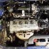
Sam44 Posted August 12, 2020 Share Posted August 12, 2020 (edited) I've got you a thermostat housing off a MK1 GT engine, if your still in need of 1. I've just picked up. Engines been stored in an old shed for 20year, forgive the cob webs other than this it's in great condition. I've picked up a tongs hybrid ct9 with the engine if it's any good to you. Edited August 12, 2020 by Sam44 Quote Link to post Share on other sites
Claymore Posted August 12, 2020 Author Share Posted August 12, 2020 (edited) 1 hour ago, Sam44 said: I've got you a thermostat housing off a MK1 GT engine, if your still in need of 1. I've just picked up. Pictures to follows I'm just removing it off the engine now. Engines been stored in an old shed for 20year, forgive the cob webs other than this it's in great condition. Awesome, looks like the water channels go straight back one either side of the thermostat. Edited August 12, 2020 by Claymore Quote Link to post Share on other sites
Sam44 Posted August 12, 2020 Share Posted August 12, 2020 (edited) Yeh the rear of the thermostate is block side or high pressure side a minimum of 2bar pressure should be maintained block side at all times. the shear fact of the top radiator hose and pressure radiator cap are also on the block side is the first warning signs with the factory radiator cap set at ???psi. This is why at high rpm (track use) and high temps we see the rad caps covering the engines in coolant. Bad position. Infront of the thermostate is radiator side or low pressure side this then dictates the flow direction as well as using water pressure to cool the turbo (packing the water molecules tight/close together) this allows for fast heat transfer and stops bubbles forming in the turbo coolant jacket. Air acts as an insulating layer stoping the coolant removing heat. Pressure stops this happening. In all honesty the E series and A series coolant design is poor to say the least using a weak pump and bad flow paths. Another good mod is to swap the hoses round to the radiator, this stops the pressure cap problems we see on track and helps maintain block pressure, using the narrow core of the radiator to maintain block pressure thus eliminating pressure cap problems. Do you need anything else I've got ep91 and ep82 parts coming out of my ears, I've got a powersteering pump but not the 2xpipes that are needed also. Edited August 13, 2020 by Sam44 Quote Link to post Share on other sites
Claymore Posted August 12, 2020 Author Share Posted August 12, 2020 (edited) Interesting on the bubbles thing, don't want boiling up in the turbo jacket. Edited August 12, 2020 by Claymore Quote Link to post Share on other sites
Sam44 Posted August 12, 2020 Share Posted August 12, 2020 (edited) this the bubbles is what is happening on cylinders 1&2 cylinder wall threw a drop in coolant pressure in this area of the block because of pump design & position in relation to cylinder head coolant flow control channels. Thank you, I'll send this out first thing in the morning I'll check my email now. A 68deg low temp thermo is a great benefit to the n/a turboed but it's no good in winter for defrosting windows the paseo came with a 76deg thermo out of factory this is the thermo I run in winter. Loving the rear axle mods great work, the radius arm bushes are a fantastic mod and weilding inch box section steel the full length of the rear axle radius arms another great modification. The radius arms are very thin and a weak point. Money received or in the PayPal account thing. Item posted out just now special delivery, next day with the post office/royal mail I've sent the tracking number to you via Paypal. If you can't receive this let me know and I'll email it to you. They will need you to sign for it. Edited August 13, 2020 by Sam44 Quote Link to post Share on other sites
Claymore Posted August 12, 2020 Author Share Posted August 12, 2020 (edited) 3 hours ago, Sam44 said: Ill setup paypal it's about time I started using this way of paying. I'll try messaging you now. I'll also clean up these messages later replacing them with comments reflecting your build. Payment sent, I've covered the postage and paypal fees. Edited August 12, 2020 by Claymore Quote Link to post Share on other sites
Claymore Posted August 12, 2020 Author Share Posted August 12, 2020 4 hours ago, Sam44 said: I've picked up a tongs hybrid ct9 with the engine if it's any good to you. I'm fine for turbo's thanks Sam, a genuine Tong's hybrid is a very sort after turbo. They'll be queuing up to buy that from you. 3 hours ago, Sam44 said: Do you need anything else I've got ep91 and ep82 parts coming out of my ears, I've got a powersteering pump but not the 2xpipes that are needed also. I'm ok for other parts at the moment I think, got the power steering stuff already. I'll let you know if I think of anything. 3 hours ago, Sam44 said: Loving the rear axle mods great work, the radius arm bushes are a fantastic mod and weilding inch box section steel the full length of the rear axle radius arms another great modification. The radius arms are very thin and a weak point. Yes I know what you mean, I was a bit shocked at how flexible they were whilst doing the rear suspension work with the panhard rod taken off. Pretty basic, old fashioned design really but not exactly a race car to start with. Can't wait to drive it again. 👍 Quote Link to post Share on other sites
Claymore Posted August 13, 2020 Author Share Posted August 13, 2020 (edited) A quick update before the rear anti roll bar. Front anti roll bar drop link replacement: The rubber bushes were looking a bit worse for wear and the amount of corrosion on the screw threads was getting to the point were removal would have been difficult in the future. Soaked in WD-40 to help loosen and reduce friction, the threads were accessible so plan b was to clean up the exposed threads with a die to help removal (thankfully not required). 10mm spanner in the centre attached to the square section and 12mm deep socket to remove the nuts either end. Top and bottom nuts, cup washers and bushes removed both sides. Arb lifted to release the drop link. Old links removed, rubbers were a bit perished. Old bush part number 48817-10020. Toyota parts. Replacement drop links Febest 0123-EXZ10F. In all honesty, not the best quality, the threaded link is fine but the cup washers have a wider dish recess than the recess in the rubbers and 2 x rubbers weren't moulded 100% correctly. The nuts are also 13mm across flats hence the wider washer dish. Fitted the drop link to the wishbone first, making sure the shoulders of the bushes sit into the hole in the wishbone then loosely attach the lower bush, cup washer and nut. Repeated for other side. Push arb down over drop link (both sides) and add top bush making sure both bush shoulders are in the arb hole. Add cup washer and nut then tighten. The previous nuts were tightened to the bottom of the thread on the link and as the replacement components were the same length and thread length I copied this method. Thankfully after tightening all the nuts down, the washers compressed the bushes and the slight moulding issue didn't matter. Yes I forgot the copper grease but I think they'll be getting changed before it matters any way ! LOL 😆 Edited August 13, 2020 by Claymore Quote Link to post Share on other sites
Claymore Posted August 13, 2020 Author Share Posted August 13, 2020 22 hours ago, Sam44 said: Yeh the rear of the thermostate is block side or high pressure side a minimum of 2bar pressure should be maintained block side at all times. the shear fact of the top radiator hose and pressure radiator cap are also on the block side is the first warning signs with the factory radiator cap set at ???psi. This is why at high rpm (track use) and high temps we see the rad caps covering the engines in coolant. Bad position. Infront of the thermostate is radiator side or low pressure side this then dictates the flow direction as well as using water pressure to cool the turbo (packing the water molecules tight/close together) this allows for fast heat transfer and stops bubbles forming in the turbo coolant jacket. Air acts as an insulating layer stoping the coolant removing heat. Pressure stops this happening. In all honesty the E series and A series coolant design is poor to say the least using a weak pump and bad flow paths. Another good mod is to swap the hoses round to the radiator, this stops the pressure cap problems we see on track and helps maintain block pressure, using the narrow core of the radiator to maintain block pressure thus eliminating pressure cap problems. Do you need anything else I've got ep91 and ep82 parts coming out of my ears, I've got a powersteering pump but not the 2xpipes that are needed also. I would have thought the overflow bottle would have been ok at containing the expanded coolant escaping from the radiator through the cap or I fail to see the function of the bottle at all?! Also if I understand correctly the coolant flows from the block to the back of the thermo housing, through the bypass hole and back down the tube behind the engine to the water pump and then into the engine. The coolant heats up, opening the thermostat and closing the bypass hole (or slowly fluctuating to increase flow through the radiator.). So coolant now flows from the block to the back of the thermo housing, through the top hose (as bypass is closed), to radiator and out the bottom hose back into the side of the thermo housing through the newly opened thermostat and back into the engine via the tube behind the block to the water pump when warm. If you swap the hoses at the thermo housing won't you be filling the radiator from the bottom now? With water exiting the top of the rad? Not sure the pump has the power for that. Also does it not increase the risk of air being trapped in the system? By all means give it a try and report back, you seem to be the forums resident mad inventor! lol😃 The way I look at it more mods = more potential issues. Minimal changes to get the best acceptable outcome. Keep it simple ...... Quote Link to post Share on other sites
Sam44 Posted August 13, 2020 Share Posted August 13, 2020 (edited) Urmm nothing mad about it. It's quite simple it's the same system, you just use the radiator to help maintain block pressure. This is how most other engine manufactures work. I take it you aren't aware of the pressure cap problems at high rpm and temp. (Track action). A very valid point of filling the system. I always use pressure\vacum to fill the system and test for leaks, but as you have pointed out if you fill by hand there is a potential for an air lock if filled in a hurry and not bled threw. The coolant flows from The water pump to the engine block, threw the block to the cylinder head using the head gasket coolant ports located exhaust side (hot valve side) located only on cylinder 1&2 (furthest side away from thermostat side\block exit) block exit located on the gearbox side\cyl 4 side of the cylinder head. it then supply's the top radiator hose (large bore diameter), heater matrix inlet also provides the throttle body thermostat idle control valve on this line, turbo coolant inlet, and if the thermostat is closed/not at temp a very small diameter bore bypass port back to the pump (all incorporated in the thermostat housing) With the thermostat closed there will be no circulation threw the radiator but the top hose & pressure cap see engine pump pressure at all times. All proformance engines run a constant 30psi block pressure to stop air bubbles forming, but factory cap pressure is .9bar this is why they fail and spray coolant everywhere on track. Block pressure overpowers the cap to the point the main seal fails. I hope this helps understand the unusual Toyota e series design. Now if we switch the radiator hoses around the bottom hose now becomes high pressure side (engine pump/block pressure) and the top hose/rad cap low pressure side. Until system is upto temp. Eliminating pressure cap issues and helping stabilizing block pressure. Edited August 13, 2020 by Sam44 Quote Link to post Share on other sites
Claymore Posted August 13, 2020 Author Share Posted August 13, 2020 1 hour ago, Sam44 said: Urmm nothing mad about it. It's quite simple it's the same system, you just use the radiator to help maintain block pressure. This is how most other engine manufactures work. I take it you aren't aware of the pressure cap problems at high rpm and temp. (Track action). A very valid point of filling the system. I always use pressure\vacum to fill the system and test for leaks, but as you have pointed out if you fill by hand there is a potential for an air lock if filled in a hurry and not bled threw. The coolant flows from The water pump to the engine block, threw the block to the cylinder head using the head gasket coolant ports located exhaust side (hot valve side) located only on cylinder 1&2 (furthest side away from thermostat side\block exit) block exit located on the gearbox side\cyl 4 side of the cylinder head. it then supply's the top radiator hose (large bore diameter), heater matrix inlet also provides the throttle body thermostat idle control valve on this line, turbo coolant inlet, and if the thermostat is closed/not at temp a very small diameter bore bypass port back to the pump (all incorporated in the thermostat housing) With the thermostat closed there will be no circulation threw the radiator but the top hose & pressure cap see engine pump pressure at all times. All proformance engines run a constant 30psi block pressure to stop air bubbles forming, but factory cap pressure is .9bar this is why they fail and spray coolant everywhere on track. Block pressure overpowers the cap to the point the main seal fails. I hope this helps understand the unusual Toyota e series design. Now if we switch the radiator hoses around the bottom hose now becomes high pressure side (engine pump/block pressure) and the top hose/rad cap low pressure side. Until system is upto temp. Eliminating pressure cap issues and helping stabilizing block pressure. I guess that why they offer higher pressure rad caps like 1.2 bar etc. It looks from your description of the system that I understand the coolant flow when hot and cold. My only concern was that in swapping the hoses at the thermostat this reverses the flow through the radiator when the system is up to temp. The top hose thermo housing outlet is now attached to the bottom hose feeding hot coolant into the bottom rad tank and the bottom hose thermo housing inlet is now attached to the top of the rad. The coolant flows from bottom to top now, I think I'll leave it as Toyota intended. Quote Link to post Share on other sites

Recommended Posts
Join the conversation
You can post now and register later. If you have an account, sign in now to post with your account.