


TBDevelopments
-
Content Count
283 -
Joined
-
Last visited
Content Type
Profiles
Forums
Wiki
Media Demo
Store
Calendar
Posts posted by TBDevelopments
-
-
its ok mate my numbers were really rough as well, as didn't know the full information but it'll get him close enough.
the stock knock sensor can read a noise level based on its feedback, like when you connect the power fc to it it'll show a numerical figure for background noise and knock. But the stock ecu doesn't do much until it fails and then goes into a safemode. The experience i've had with these is the ecu will obviously have a figure for safemode activation, i've seen this trigger a few times and the sensor be ok but 9/10 the sensor fails, engine goes into safemode and protects itself.
In toyotas eyes just like fuel cut it'll only ever happen if there is something critically wrong with the engine and its setup, so the fact it blows £150 worth of sensor everytime doesn't even cross there mind as like you said its an last stand fail safe. But when tuning if not setup correctly or run right on the limit then you hit this problem more often than not.
Its a shame you can'get something like an emanage or even the power fc like i run and get it mapped as at 9.0:1 it would make a much nicer car to drive on a 200bhp road going setup. Much more responsive. better fuel economy and just more efficient all round. It would also make more power and torque per PSI of boost compared to the lower compression examples.
Again quoting the 3sgte tuning i've done over the years we only ever drop the 8.2:1 which is stock CR for a starlet until we get near the 600bhp range on pump fuel. So it always surprised me how low the glanza was out the box, Almost reminds me of the old ford tuners where as soon as you put a bigger turbo on you'd rip all the compression out of the thing to make 400bhp (7.5:1) and have it all topend and low down and midrange torque would be terrible. But with the new setups and the way tuning has evolved you really don't need to do that anymore until you start going silly. and 200bhp is only a light fettle as far as I'm concerned.
But if you can't go that route then the 1.7 or 1.9mm range of gaskets should do you fine. I'd aim more for the 1.6/7 personally to account for the unknown numbers in the calculations. Not sure on the sizes available to you.
right going to crawl back into my hole, lol message me if you guys need anything else.
Tim
TB Developments
-
numbers and thickness's on the first page mate.
Valve relief won't make a huge different 0.1 point at most
Tim
TB Developments
-
ringlands only normally go on these engines because of leaning out or detonation... This basically points to it not been setup up correctly i'm afraid buddy

right i'm off to bed, have some fun with those numbers, you have my number if you need me
-
that was just machining specs of the angle of the valve cut etc doesn't really give me piston relief CC
Personally i'd just go with the 9.0:1 and stick an emanage on there. If you've cracked 3 pistons on your old engine then there was something seriously something wrong with your setup. Like i said i've run my blitz K1 at 1.1bar at 200bhp for the last 70,000miles and its never missed a beat, this is because its all setup properly on bog standard engine internals.
-
ok going on some really rough numbers nere. guessing on alot of things
Bore 74mm
Stroke 77.4mm
Head Gasket - Variable
Head Gasket Diameter 76mm
Piston to Head Depression 0cc
Combustion Chamber 39cc
Piston Dome CC (set at 0cc because i don't know valve relief so this will give a lower reading once i know this)
1.0mm Gives 9.00:1
1.2mm Gives 8.83:1
1.4mm Gives 8.68:1
1.7mm Gives 8.45:1
1.9mm Gives 8.31:1
Remember these will drop once i know the CC of the piston dome and valve relief.
like i said some really rough numbers
Tim
TB Developments
-
well not as much as if you get this wrong and then have to rebuild it again ;) engine building to a proper level isn't just spanners and screwing things together. Alot of people don't realise that
-
not always mate, 3sgte for example are 86mm piston bore and the gaskets come in 88mm
-
again mate should have said could have had a nice cometic one added to the piston order ;)
-
well you know i'm here to help if i can. Wish you'd have let me build the engine properly from the start ;) would have used the 74.5mm and then used the torque block to correct for the factory relaxed block bore and honing.
TimTB Developments
-
i'm speaking my wiesco contact at the moment in america and trying to find out the manufacturing specifications used when they were built.
From that i can work out a rough compression ratio and then change the gasket thickness around to get something.
what i do need is a bore diameter from you of the head gasket your going to be using
Tim
TB Developments
-
on first fire up raise the revs to 2500-3000rpm and run for 20mins. Check for leaks and issues the entire time.
Don't let it settle below this or it'll start to glaze the rings.
god tip about the metal filings produced by running in an engine, but this is why i supply and fit a high strength magnetic sump plug on all my engine builds i do. Something i highly recommend to all engines rebuilt or not
Tim
TB Developments
-
could have got you your scat rods with the pistons and everything else mate ;)
Yes there is a correct orientation. If you look on journal the notches that locate the bearings on a clockwise rotational engine these go on the exhaust side of the engine. Its all to do with bearing loading on rotational thrust
Tim
TB Developments
-
not yet, there is alot more to calculating CR that just punching in numbers. Really the parts want CC'ing to work out correctly.
Bore and stroke we know.
But the head gasket thickness is a variable
But need to know head gasket bore (as there bigger than the 74mm piston bore)
Need to know exactly the CC of the cylinder head (these do change between engines,and even seen differences from one side of the engine to the other)
Need to know exactly CC of the piston valve recess
Need to know exactly the piston face below the deck height from a dial gauge
information I can't really get from just looking on the internet, race building involves doing this with equipment i have in the workshop.
From that I can work you out some accurate numbers
But they are designed with a 9.0:1 ratio at 1.0mm gasket. Last time i installed them this was about correct. so fitting the 1.4mm gasket you already have is going to bring it into the high 8's
Personally i'd just get a proper ecu setup so it can all be setup correct and just keep them at 9.0:1. I'm going out on a limb here but i'm guessing you won't be exceeding more than 1.3bar on pump fuel anyway?
Tim
TB Developments
-
you do realise the knock sensor in standard form doesn't actually do alot it doesn't detect little bits of knock and retard the timing. In standard form it almost acts like a fuse, that will blow when it detects large numbers and this throws the ecu into a safe mode. So don't feel its "working overtime" by adjusting the timing to suit because it just doesn't
I do agree with adam that this engine should be setup with a proper ecu, but i also believe this on all starlets that reach there fuel cut level because this FPR, and fuel cut defender is just bodge tuning. I wouldn't take your current setup as bullet proof either as you said yourself you've cracked 3 pistons. I've been running 200bhp on my standard engine starlet for over 75,000miles now and its never missed a beat.....Why because its properly setup with a power fc ecu tuned for the modfications i have.
But anyway back to the compression ratio.
The wiesco pistons have a static compression ratio of 9.0:1 out the box calculated from a 1.0mm head gasket. Any increase from this size is going to lower the compression ratio.
If my engine was to blow in its current 8.2:1 CR state (which by even turbocharged terms is very low) i would upgrade to a 9.0:1 setup and tune from there, this is going to give much better response off boost and a nicer smoother engine to drive and under 200bhp you won't have any issues.
For example on the 3sgte engines we do under 400bhp we run those at 9.0:1 and the only reason we drop it above that is to give the block some stress relief because they are known to crack, which the 4e doesn't suffer from. Hell we even ran a 850bhp drag car at 10.0:1 at 2.2bar of boost on a gt4094 turbocharger and ran fine until it cracked the block. If the block was stronger this would have been as awesome setup.
Tim
TB Developments
ps,
det cans are a listening device that all mappers should use when mapping your car, this allows them to hear the early signs of detonation (pinking) and increase fuel or reduce the timing.
-
keep looking mate, i found 2 just buy searching forums, ebay and yahoo japan. Got my last one brand new still in the box for less than £60 ;)
-
thanks mate

only got the ic pipes to build now, mount the FPR and get it remapped with some 375cc injectors and 1.2bar and that will be it.
although many have said thats safe on stock internals if the head gasket goes or a piston i'll rebuild with forged pistons and metal headgasket but not change the spec anymore.
got a 500bhp mr2 to build and play with now so this is hte daily
Tim
-
thanks guys, well local boys you know where my workshop is just pop down when your free, give me atxt first to make sure i'm in so you don't waste a journey.
I've still got the P/S system inplace, if you look at one of hte bottom pictures you can see it hidden away, and that topmount air feed has it as well. As for the fabrication thanks my welding was all self taught
i don't plan to make those but if people want custom fabrication doing then i'm sure i can sort something out Tim
-
yeah no worries mate your always welcome
-
been to long since i updated this. so here goes.
cars still been running fine, never let me down once. just been tweeking the setup and a few service items.
Main thing was the clutch, the exedy basically fell apart on me the rivits all came loose on the friction plate and was making a hell of a noise, done a few mr2's with the same clutches recently and they've all done the same as well, so feel its a common failure. I replaced it with a toyota friction plate as the exedy was nothing special, and re-used the exedy heavy duty pressure plate. runs much better now with just as much grab
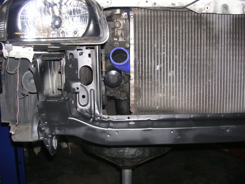
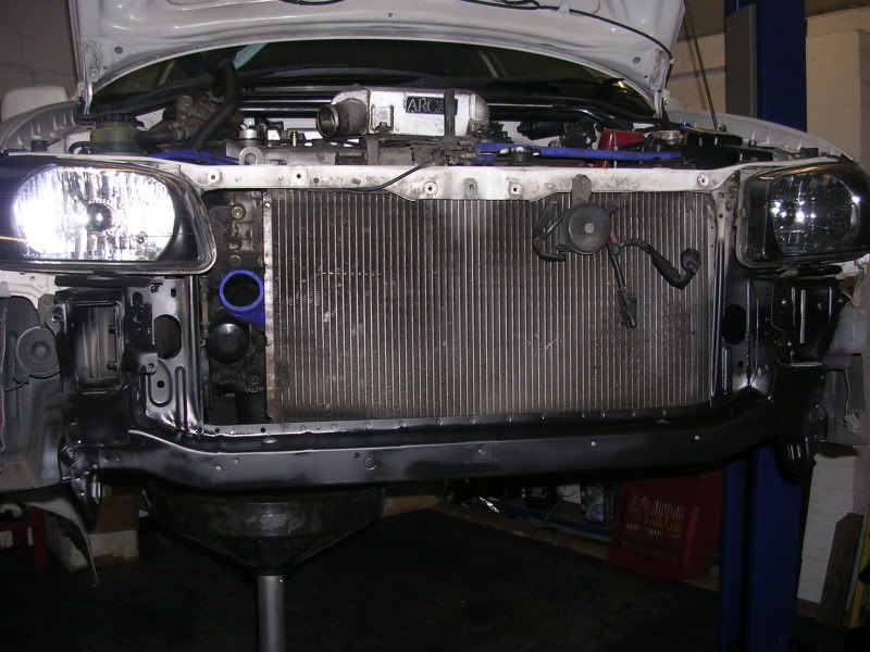
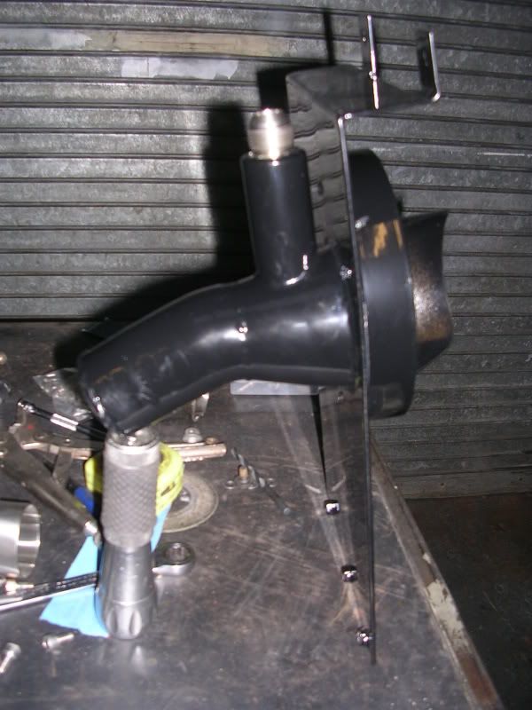
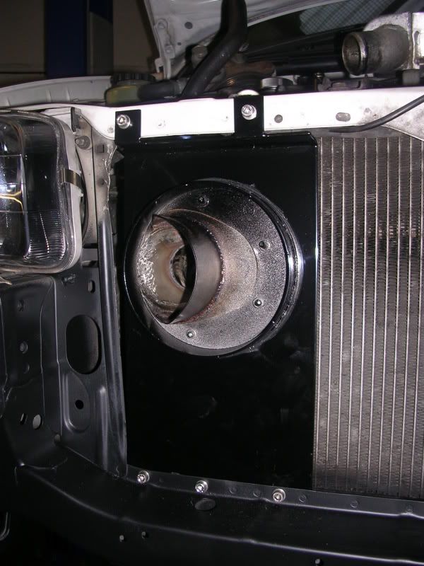
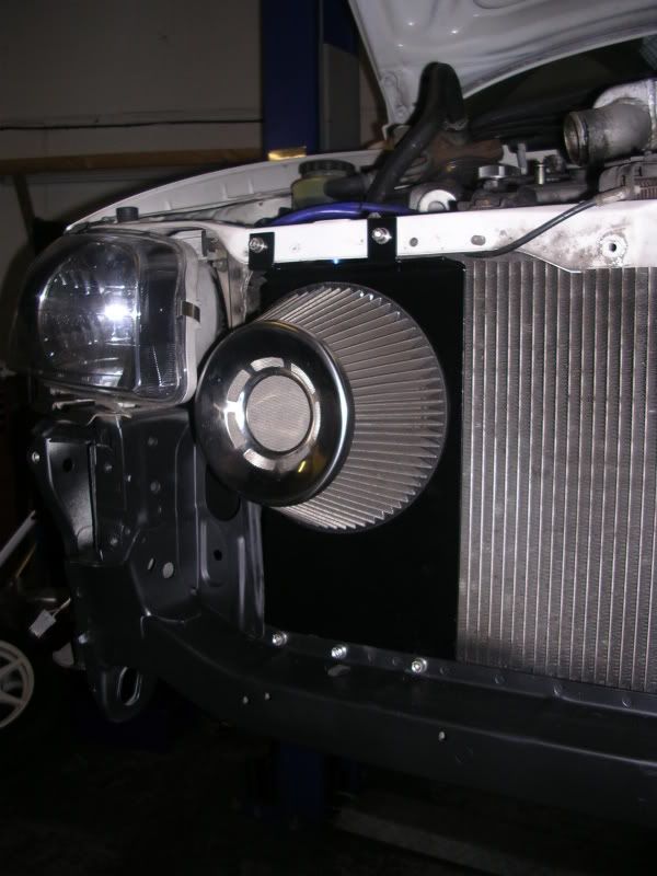
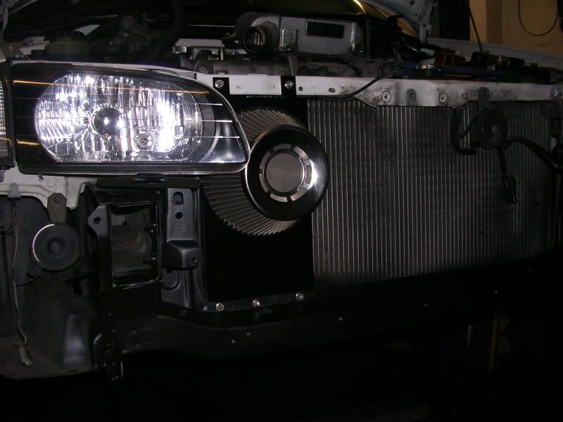
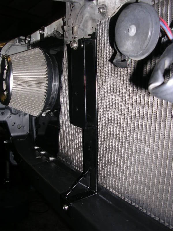
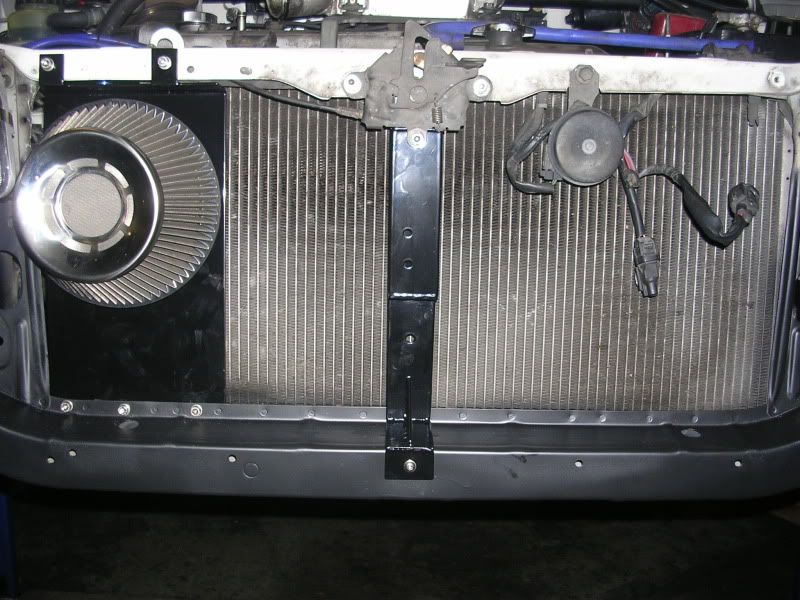
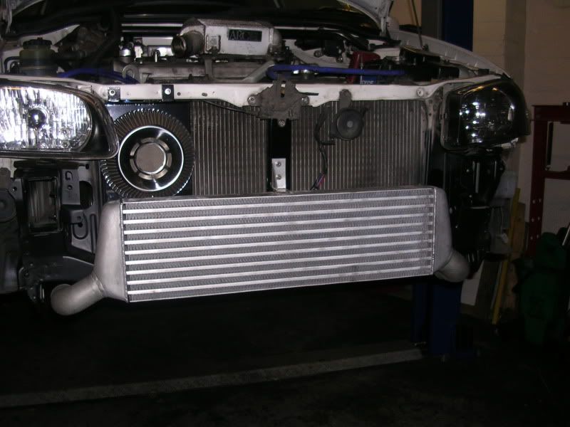
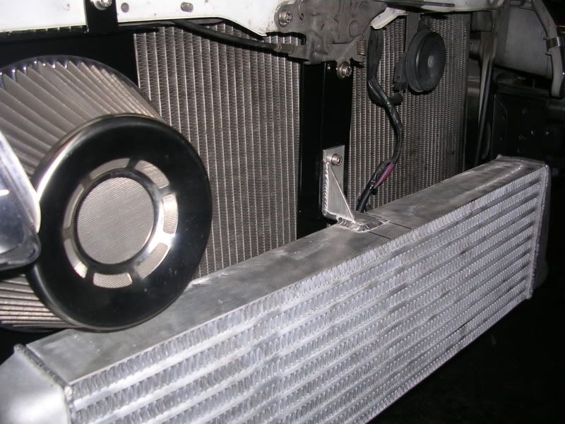
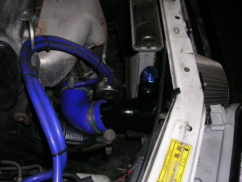
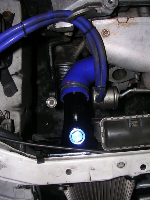
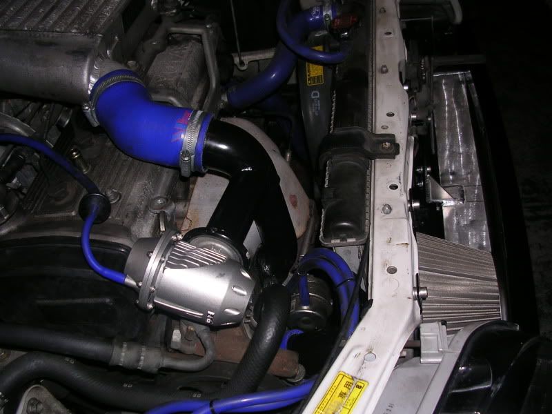
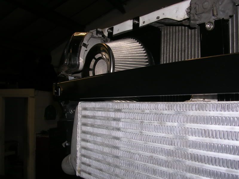
the other job i finally got round to doing was fitting the front mount intercooler kit and moving the blitz filter to the front bumper, its currently at 1bar but going to 1.2bar soon with the remap and the bigger injectors. i'll probably leave the car there and just keep it maintained as it now spins through 1-3rd anyway so fast enough for a little daily drive.
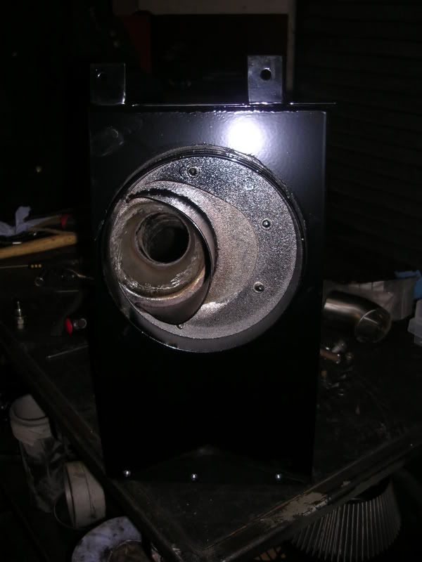
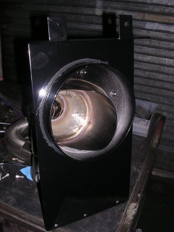
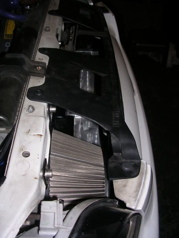
The front mount filter kit i wanted to do something a bit different so hard mounted it over just silicone and cable ties. i did a test fit and found i got alot of boost creep with the air hitting the side of the filter and acting like a ram air effect. so i put a divide inside hte filter so that it still pulled in cold air but didn't get forced down over 100mph. i know its technically not ram air but it was making the filter over efficient and the wastegate even through ported couldn't keep it below 1 bar.
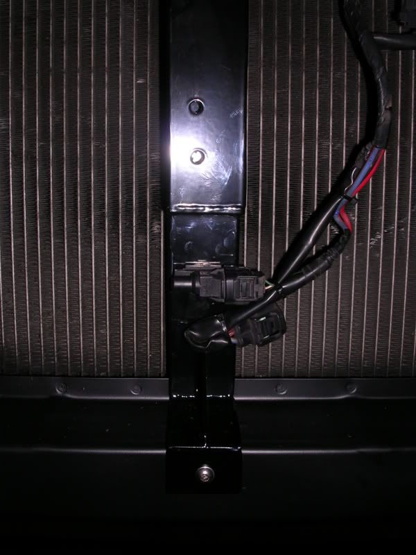
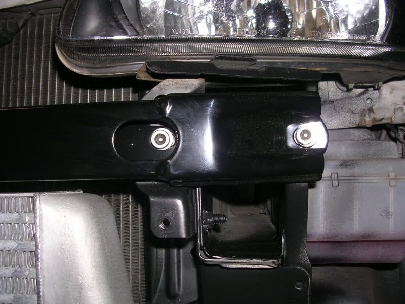
i also redesigned the fittment slightly and remade the main support bar for the catch so the intercooler could sit back futher. it now fits without any bumper cutting needed what so ever, also the pipes that run under the bottom cross bar into the engine bay don't hang down, they are actually about 1/2" higher than the bottom of the bumper.
if your wandering why i have the front mount ic fitted and still running the topmount its because i'm going to be clocking the turbo and making my own ic pipes so rigged it like this for now until i have them made up.
Let me know what you think of my work. Oh the blue cap on the filter is a blanking plug thats there for a cam case breather attachment but i've not got that sorted just yet.
-
F1 manifolds often crack, so do touring cars, they just don't cry about it. I very much doubt exhaust gas pressure is a problem with cracking. Even at 900 degree's you'd need 10 x the pressure to even get close. However all your other points are correct.
Lastly slip joints IMO aren't the way to go, the idea is as the material warms they grip to seal, when the manifold is extremely hot it'd take a lot of pressure to move, they'r ok when there cooler, good for complete heat cycles not for daily drivers where the EGT's will get higher (say on the motorway) then cool a little when at idle at the traffic lights, but never completely cool. They are also only used on thin wall manifolds which certainly wouldn't last on cars that are daily driven etc.
Turbo's fail, manifolds fail, engines fail eventually. If you want them to last longer go slower, map with more caution etc etc. We give a 3 year warranty on our products which is the same as most manufacturers I.e. Toyota when the cars were new. And our products are performance related

i was trying to stick up for your work saying its not yours that all manifolds will crack, wasn't trying to get into a debate
Tim
TB Developments
-
ah ok mate.
tell him he needs to change his shop name. thats going to lead to some serious confusion
Tim
TB Developments
-
yeah the locking nut inside has come loose mate. if its doing this it also means the bottom part under the diapham is loosing boost through the slack connection
Tim
TB Developments
-
got an email?
there is a company called spigotrings.com i just sent them an email as could do with some myself for my p1's
Tim
TB Developments
-
i have my manifold, turbo and downpipe all professionally ceramic coated which will show what insulation will do at its best. car can be running and manifold is only warm to the touch.
before and after results i didn't do power but boost came on harder and spool to 1bar dropped by around 400rpm an a K1 turbocharger
Tim
TB Developments
running in fresh 4efte
in 4E-FTE Engine Discussions
Posted
no we have them made for us, just a straight sump bolt replacement with the magnet in the middle, but had alot of issues with the typical alloy ones on the market with people overtightening them and stripping the threads out so I've had these made in steel, zinc coated with a high strength magnet fitted in the middle.
Tim
TB Developments