

Claymore
-
Content Count
660 -
Joined
-
Last visited
Content Type
Profiles
Forums
Wiki
Media Demo
Store
Calendar
Posts posted by Claymore
-
-
27 minutes ago, Reptagon said:
Thinking of doing turbo valve springs to increase the rpm (hopefully to just under 8k) and then 5e rods to increase compression but I still have to look into that more
Got it for free off of a mate and with itbs as it will be more air per cylinder in my head I think it will lean out a bit
Fair enough on the FPR, I presumed you'd be going with a piggyback to sort the fuelling side of things.
This guy has done a pretty good write up of it. He couldn't get the fuelling right with adj. FPR and needed piggyback (hence my presumption). Don't forget the wideband o2 for tuning purposes.
Looking forward to the progress

-
6 hours ago, Reptagon said:
Yeah I've found that tbh and this new box getting me there quicker is literally the perfect combination for it. I'm curious what the difference will be between stock man, corolla Mani and ITBs with that cam will be though
Dynoooooooooooooooo!😝 Sounds obvious but we'd all be interested to finally nail down what mods are producing the best gains.
6 hours ago, Reptagon said:I then attempted to fit my 4-2-1 manifold and it didnt go well as the pipes didnt line up and i only had a coupler no flexy pipes so for a week I had no exhaust on my car and it sounded like this. Also I can see that some point around here was when i cleaned up all the gunk from my rub strips and made it look a little nicer.
Now whats for the future of this build. well the parts I've got already are a fuel pressure regulator to fit, ITBs, 4-2-1, new anti roll, mr2 seats and a glanza spoiler.
The ITBs are from a triumph I believe and we're gonna make runners using my old stock manifold and then using a vacuum box for the map sensor and then figure out how to get an idle to work and things like that.
Which 4-2-1 manifold did you get? I've heard of the corolla cast one and the OBX for the 5e being converted to fit before. Again there's no dyno before and afters to show the differences. Not sure the fuel pressure regulator will improve much on an N/A unless the current one is a bit tired.
4 hours ago, Reptagon said:I'm just trying to find an exhaust system for an NA preferably cat back that will work but I'm debating deleting my cat idk if it's worth it though. Kinda a similar thing atm with power steering as I don't know how much the whole system weighs and how much difference it will make
I've seen some results posted with a corolla intake and throttle body, stock cam, 2" straight though exhaust. Made 86.6hp. Deleting the cat as you know is an MOT failure and swapping it out after the test will make the car "unroadworthy" in the eyes of the law so void insurance too. Universal fitment sport cats (200 or 100 cell) are available. From the other mods people have done it seem that the corolla manifold is a good, cheap, easy gain for N/A. Itb's are more suited to higher revving engines than the stock 4efe, shortening the inlet track significantly will most likely lose low down torque. Hopefully the improved breathing from the cam and an increase in redline will help. There have been a couple of ITB builds on here but unfortunately there haven't been any dyno graphs posted to show the improvements gained. It's best to mount the bodies as close to the head as practical to improve response and then play with different trumpet lengths to suit.
All I can say for sure is that N/A tuning is a minefield and some mods improve and some will harm performance depending on the rest of the setup so testing and tuning is most important.
Very interested to see the results.
-
37 minutes ago, Sam44 said:
Love your ability to think of how to balance this issue (real tunning of the engine). It's a very real option for the car thanks. I can always try it and see, I hope this help you understand the level of tune of the setup everything is there for a reason, every component. The options for this production line car are near limitless, with most options production line components.
the rpm drop out on immediate off throttle (with this flywheel and clutch setup) is killer for power on the roads. Definitely suited for track use. It trips me up all the time. Bliping the throttle would make me look like a 40year old tit lol. But the acceleration is utterly ridiculous. makes me laff every time. There is no need for me to go coil on plug but the corrola dis less system might be on its way in the near future. I'm eyeing up a corrolla.
Are you aware the 4efe crank is also lighter (they are marked 4e, the heavier 4et marked cranks are there because of the lowwer compression ratio out of boost).
The heavier pully would also help prevent crank walk killing my thrust washers great idea.
I have started to fouces on the gear shift it's important to get it right it's very fast Requiring me to kick the clutch.
Thanks, the parts bin raiding opportunities are what drew me to the starlet along with the aftermarket products available. Seems to be well covered from "mild" to "wild" builds. The hardest part is to cover all bases with track behaviour and then trying to have a docile "freindly" street car to drive for the rest of the time. Compromises sometimes need to be made. Hopefully the heavier pulley may just take the edge off and make the street behaviour acceptable for you. It is easy and cheap to try anyway. I do like the idea of using the corolla crank trigger and dizzy less system. Toyota O.E. development FTW.
I had heard of the differences in cranks from 4e and 4et, I also read that someone had disassembled a late 4efe engine and it came with a 4et crank?! Could be internet BS but you never know.
-
21 hours ago, Sam44 said:
Answer to your edit:
To answer your edit: that's if I'm on a straight strip run or quarter mile. Track and street or different altogether with a variation of widths and corner angles (exactly why this system was invented because the first F1 turbo engines struggled with out of corner acceleration against the already proven normally asperated counter parts) and that's f1/track use. Gordini famously wrote in his auto biography all other turboed engine drives complaine about turbo lag out of slow corners, his driver's asked what is turbo lag. Fantastic book a must read.
I remember recently seeing a modern F1 driver describing his drive in a turbo era F1 car (presumably without als) and the technique of heel and toe throttle actuation on braking and turn in to keep the revs high for spooling the truck sized turbo ready for corner exit! Sounded like quite a handful.
21 hours ago, Sam44 said:When we get to the street stop and starting. the close ratio box using the 4+:1 ratio final drive lsd will combine to give killer 0 to 60 mph times. The turbo tech will allow me to jump gears and even move up earlier to get to the all important 3 threw to 4 (1:1 engine output gears).
Now I bring this up Im missing the heavier 4e flywheel which stores more energy in the rotating mass which helps me to be able to do this keeping engine rpm up and power ready against the ultra lightweight and low anertia fast accelerating lightweight flywheel and small weight sensitive clutch I'm on at present. It's been areal bug bear. The only consolation is the flywheel was a second hand bargain and combined with the box and other mods it's saved me a small fortune and time on a digital ignition system.
I take it you're already using the 4efte crank pulley? As you know this is heavier and would add mass to the rotating assembly. Might help bring some of the missing mass back.
-
13 minutes ago, JamesG said:
I enjoy modifying it and making it my own but am also not very keen on making changes that cannot be put back for that reason.
Spot on. Same for me with certain cars. 👍
-
3 hours ago, Georgehburroww said:
Hi everyone,
im going to be getting my car remapped with a wolf v4x stand-alone at TD, before I go just want to make sure she’s all ready. I’ve recently got a new downpipe and exhaust and there’s no hole for the egt sensor. Previously before i put the exhaust on the previous owner had the egt sensor just dangling in the engine bay (dodgy I know) I am aware egt sensors generally read the exhaust temp to make sure the car it up to temp to allow more accurate fuelling ect... so my question is... will it be something TD will most likely map out? im running a td04 set up and only really shooting for 200hp. I’m running the standard 02 sensor and would consider upgrading to a wideband aswell for more accurate tuning.
if anyone has a wolf v4x or can tell me anything about what they have done in terms of the egt sensor and o2 sensor it would be greatly appreciated!!
tia!
")
I pretty sure the stock O2 sensor is before the cat and the temp. sensor is after the cat on the stock 4efte setup. Most forum search results say when fitting an aftermarket downpipe they remove the temp. sensor as its for cat warm up efficiency and no aftermarket downpipes have the fitting anyway, probably best to let TD guide you on that one.
I would deffo recommend a wideband o2 sensor and gauge on any tuned car as a failsafe atleast. If the fuel pump gets tired or the fpr starts to fail at least you have a gauge on the dash telling you what the air fuel ratios are to help prevent engine damage from leaning out.
Not sure how the wolf works but modern standalone ecu's should be able use the wideband data for all sorts of stuff. Closed loop fuelling corrections, targeting afr's etc.
Don't forget to report back on how it goes, never seen any results from a wolf mapped glanza before.
-
52 minutes ago, Sam44 said:
Put it this way what ever positive pressure (boost pressure) the seals can withstand on both compressor and exhaust turbine (exhaust back pressures, these are generally higher) the seals can equally take the opposite (negative) pressures.
There is of course oil pressures to consider.
I can see how you came to the answer you did. I've not explained the engine breather system. This is setup to maintain a set relatively constant negative pressure to stop piston double pumping (know as engine parasitic losses) and promote piston ring seal. Lol ive left this off here for now as I can imagine the head scratching going on. again this uses 3x 1way check valves, oil catch tank and an inline restrictor. Between these 2 the turbo will be able to produce say 3psi at a higher rpm than it would normally produce. as the actuator reacts to this set pressure the arm opens and volecity and turbo rpm take over.
It can be hard to understand pressures and flow rates (volumes). And in most cases if you increase 1 it will decrease the other because restrictions will be increased or decreased these restrictions can also affect velocity/speed yet another area (venture affect). These restriction apply to both the intake and exit of the system/sytems.
Look into turbo Serge and why this happens will help you understand alittle better. This also helps explain the blow off valve idea as a negative pressure is produced and the pressure increases with engine rpm raise/engine throttle opening in an enclosed intercooler system.
A negative pressure/vacuume of around 20 to 23psi is our target.
I do never mean Any of my questions to be offensive in any way. understand I'm on a club based web site. your questions are valid, I've not explained the full system or given any target figures.
I ask my questions so I can best explain to you, gauging your understanding of pressures and volumes.
No hard feelings Sam, I was trying to understand the system (as you said without the full description / info) hence my questions basically trying to help on points I thought you may have missed. Looking forward to the results, bit of F1 nostalgia making a comeback.
 .
.
-
23 minutes ago, Sam44 said:
It's not fully closed. the throttle control arm will be setup to control negative pressure.
How much negative pressure are you thinking about.
You do realise the range of both positive and negative pressures,
Do you understand engine throttle and manifold pressure.
I didn't realise the throttle would be partly open, this would allow air into the turbo to build boost.
I have no idea about the amount of negative pressure, hadn't got that far.
Nope, not my engine setup
Think so.
It's nice to see something different and was trying to get my head round it. I'm excited to see the results Sam. Keep us posted.
-
11 hours ago, Sam44 said:
Your quite correct on the throttle body before the turbo. Gordini first introduced these on the Renault engine in the late 1980s F1 era to reduce turbo lag. It simple removes load/air from the compressor wheel allowing it to free spin. As the throttle opens slowly it increases air velocity into the compressor inlet.
I'll have to get in touch with visco about copies for sale but I do have the old original full kit that is good just seen better day I might sell.
The additional pwm table on the aem ECU will operate the hks blow off valve located just before the engines throttle body it will run operate off the 4efe tps (potentiometer) on the pre turbo throttle body which opens off the hks adjustable actuator. The blow off will open at set low turbo pressures in relation to rpm/engine load. This will remove load on the turbo compressor wheel (both removing back pressure and incoming air to pump, creating a vacuum) and allow more air to enter the engine and drive the exhaust turbine.
The hks actuator is plumed directly into the turbo compressor housing pipe (direct boost build).
The car came with the Baily's bov valve (bucket type) I was warned about high maintenance if you do not run a oil catch can and good engine air filter, after some research I found the early hks blow off valve was the 1 for me very robust.
The system might sound complex but it's really quite simple, the only real hard part is setting up the pwm table.
The aim is to get the turbo spinning and keep it spinned. (Anti lag)
1 area we have got a trained eye on will be the engine throttle control, with all the modification we have brought to the simple 4efe system we are hoping to see a very smooth controllable throttle/power delivery helping the map sensor plot an actuate procise fuel delivery. (Engine efficiency).
I was joking about making copies of the exhaust Sam!
I'm still getting my head round the proposed layout but I'm pretty sure that I've read the oil seals in the turbo need changing for running in a vacuum or the oil will be drawn past them into the compressor housing and engine?
Maybe I'm missing something but when the pre turbo throttle body is closed creating a vacuum from throttle plate to manifold throttle plate (to maintain turbo spool), it also prevents air being drawn into the compressor so it can't produce any boost? The pre turbo throttle is opened by boost pressure to a hks turbo actuator operating the pre turbo throttle body but it won't see boost because the turbo can't produce any so it won't open again?
Dunno but you've given me a puzzle to think about again.
Edit: Forgot to say, with the six speed box and final drive ratios you should be experiencing less rpm drop between shifts also? So shifting up at 6000 rpm drops you down to perhaps 4800 rpm and the turbo should still be well on song at that point with a decent dump valve and responsive external wastegate setup and modern EBC? Does the als only really provide benefits at low rpm acceleration as the boost potential from the fully spooled up turbo is available there?
-
On 8/16/2020 at 10:40 PM, JamesG said:
Looking good, handy little guide. Thinking about putting one of these on mine in the future. Does look a bit daunting drilling the holes in chassis leg but well worth it for the handling gains.
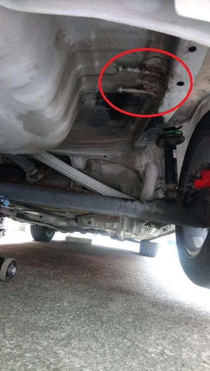
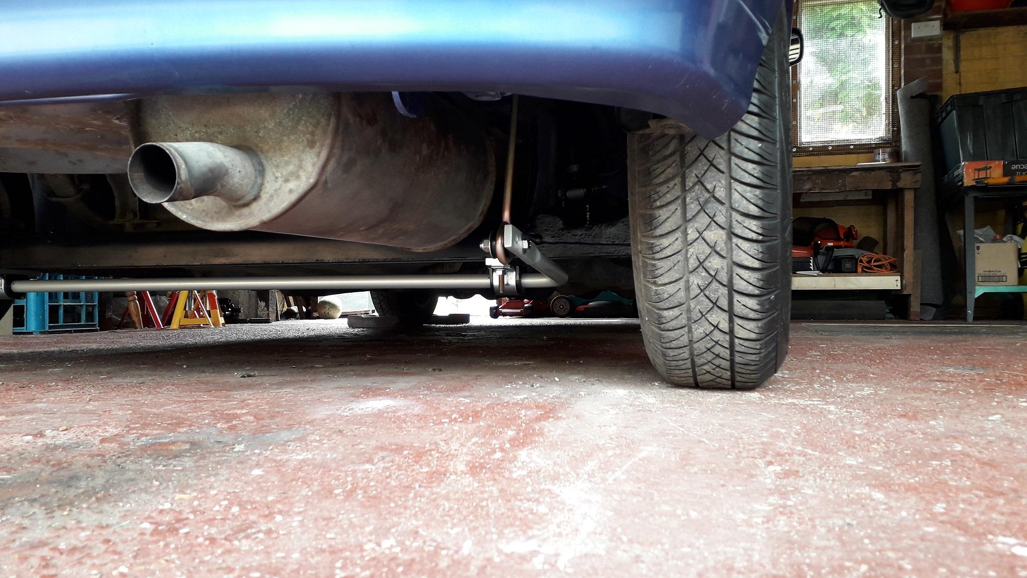
Thanks mate. For me the decision was easier! I care about all the cars I've owned (some more than others) but this one was only £850 and I was happy to drill it. If you look at the picture below (seems familiar?) you have already discovered the exhaust reinforcement bracket on the drivers side that I was noting above.
As your glanza is one of the cleanest I've seen for a while I don't know if I'd recommend drilling holes in that beautifully clean chassis! I understand it's your car and you can of course do what you want to it, but in the future cars of your level of cleanness will command a price premium. I hate seeing cars as investments but sometimes it can't be ignored.
There are alternative arb's like the ultra racing. They're non adjustable but are available in 2 different thickness's. They look to attach to the beam the same way but the arms point forwards and look to pick up on existing chassis points.
I've not fitted one of the ultra racings and cant seem to find the instructions to confirm this so I'm only going off the photo!
Might be an option for you to investigate. I wish all companies made the instructions available on their website.
*EDIT* Found a rear photo of the arb drop link mounting bracket installed. Rust repairs immanent!

-
On 8/15/2020 at 7:15 PM, Sam44 said:
A good friend of mine has used the old zisco manifold and made a jig for this a new manifold/turbo kit.
The turbo has evolved again this time using a td05 20g antisurge compressor housing modified to fit the 13t hybrid. I could not trust the surge I was getting with the 4e skinny rods. This should also pump more volume of air but at a smoother rate in the rpm band.
The old 1 was good just heavy corrosion.
He is fitting this new kit to car whilst I'm away.
I'm currently making the pre turbo throttle body.
Made up of 2x back to back 4e series throttle bodies 1x 4efe and 1x ,4efte striped out using a hks actuator to operate/open with turbo boost pressure.
Time to start fabrication.
All new nuts bolts and gaskets used.
Refreshed.
1 word : PURPLE
If this is to lazy I've have a rare tdo4hl exhaust housing and I'll use an 11 blade turbine. That's is alot lighter than the 9 blade option I'm running now.
Bigger tdo4hl exhaust port.
It's all coming together, and I must admit the help I've received from a young uni student I work with, ho has helped build up this ep91 and thought me a few tricks when it comes to mapping.As well as his attention to detail. Many many thanks.
Using the close ratio gearboxes gives outstanding acceleration, this allow daniel to run big ignition retard low down in the rpm band. What this does is produce high flowing very hot exhaust gasses kicking off turbo spool.
He just needs to stop loosing my tools !!!! Haha.
Looks like some good progress, interesting with the pre turbo throttle body. I take it this is in addition to the normal throttle body? Going to be used for 80's F1 style anti lag system? Is this still the 4e or have you built your 5e up yet?
Also if you've got a jig for the manifolds how about making some copies!?
-
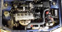
Super clean underneath too 👍
-
Nurse! He's out of bed again! 🤪
At least its got offers on it! £50? Lol 🤣
-
Whiteline adjustable rear anti roll bar install:
Vehicle was safely set at ride height and the wheels removed.
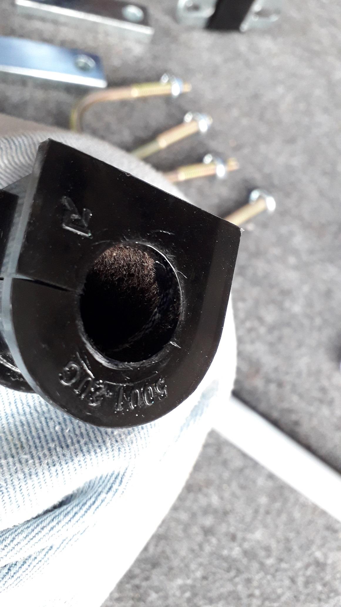
First I assembled the D-bushes to the anti roll bar (arb).
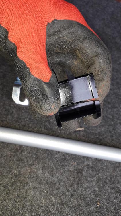
They are a new design that is "grease free" having a PTFE fur lining. Stops the need for grease which can attract grit and wear the bushes out faster.

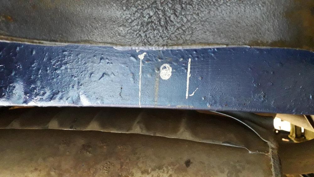
Metal saddle clamps pressed over bushes, I marked the centre of the bar and the centre of the rear beam.
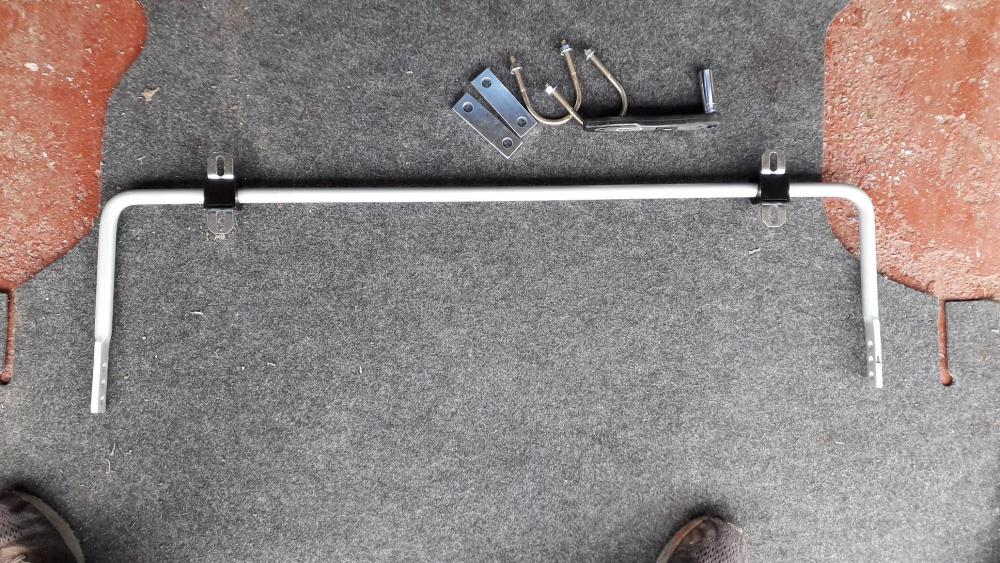
Installed the arb centrally with the U-bolts over the beam, through the metal clamp blocks to attach through the saddle clamps with 2 x shakeproof flange nuts. I then attached the arb drop links to the central hole on the arb arms with the chassis brackets attached to the top.
.thumb.jpg.274eb228f4f566dd0b1a38333b6cf4d4.jpg)
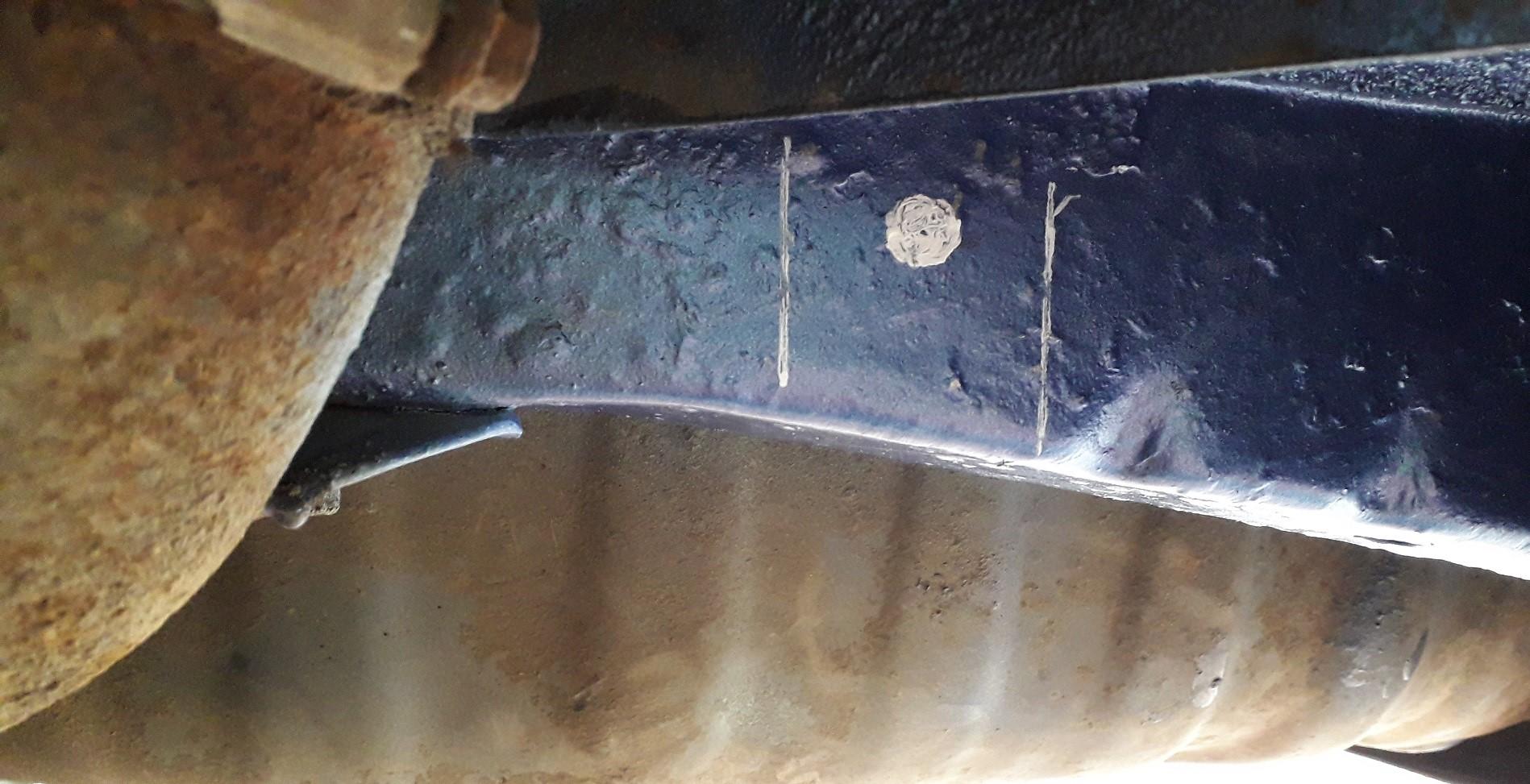
Rotated the drop links into the most vertical position on the chassis rails I could and marked the position of the mounting hole and the bracket sides in white paint pen. I then tried to insert the drill and found I would need to lower the hole to allow the chuck access.
A word of caution: on the drivers side behind the rail is a reinforcement plate which is used to attach the exhaust mounting bracket. I transferred this line to the outside face in pencil to know how far back the hole could be drilled. Any further back would have been a real mess to mount the nut and washer. The passenger side is clear and the drop link can mount vertically, the drivers side is slightly angled forwards.
Passenger side position

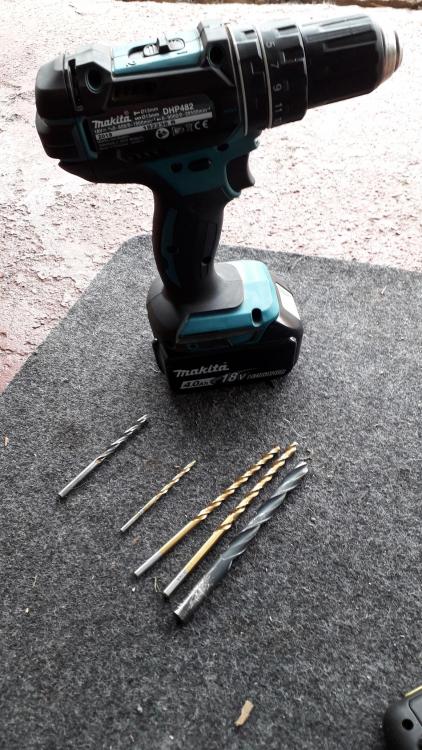
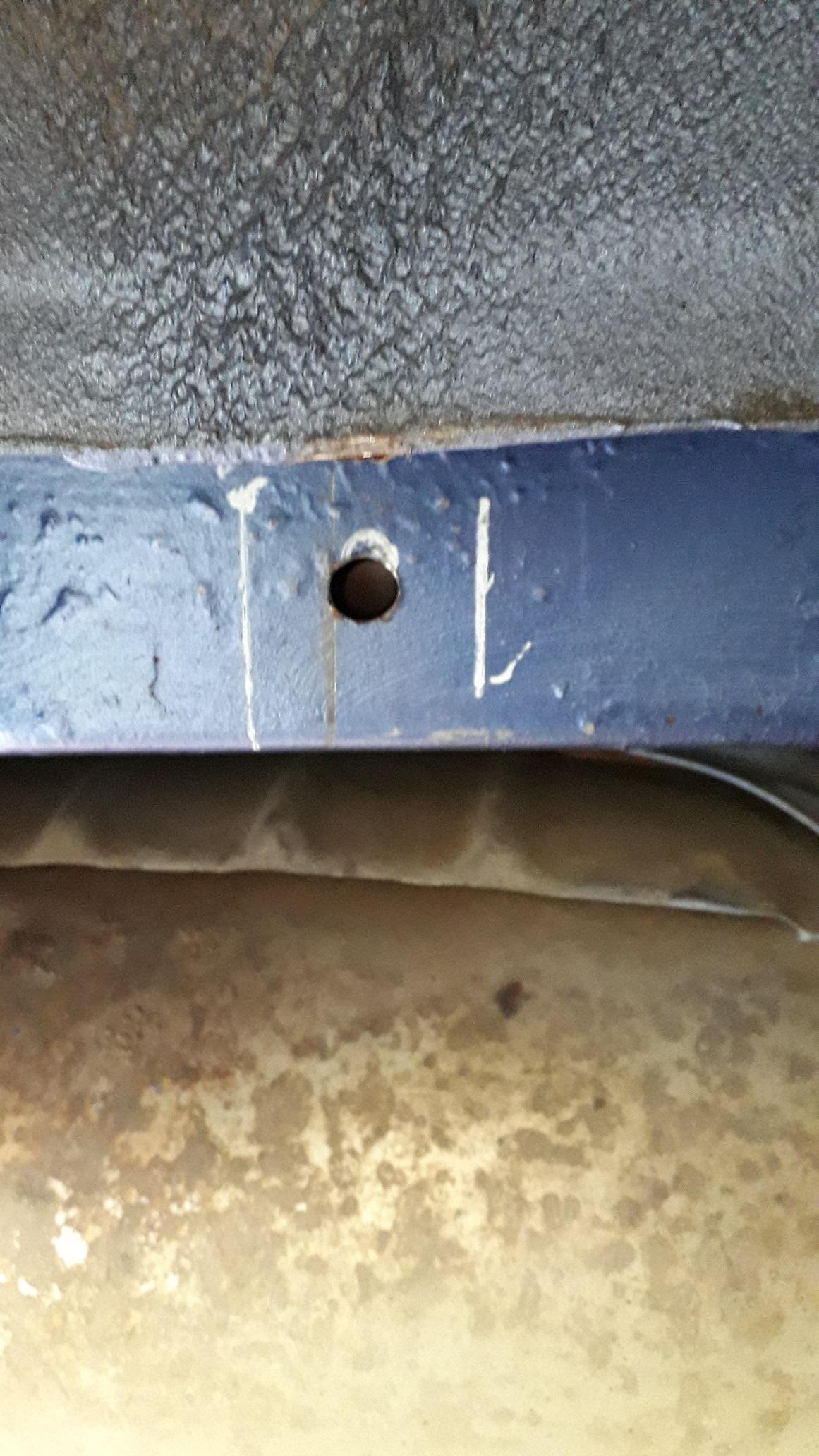
With everything measured and checked it was time to drill the bastard! Centre punched the holes, and started out with a short 5mm bit, then a long 5 x 132mm bit to make it through the box section and opened this out with a 6 x 139mm drill bit finally followed by a 10 x 139mm bit. Light pressure forwards but firm grip to reduce chattering. Long drill bits and small chuck / drill body are essential as space is very limited. Make sure you drill straight and flat.
Holes drilled, zinc primed and then top coated.

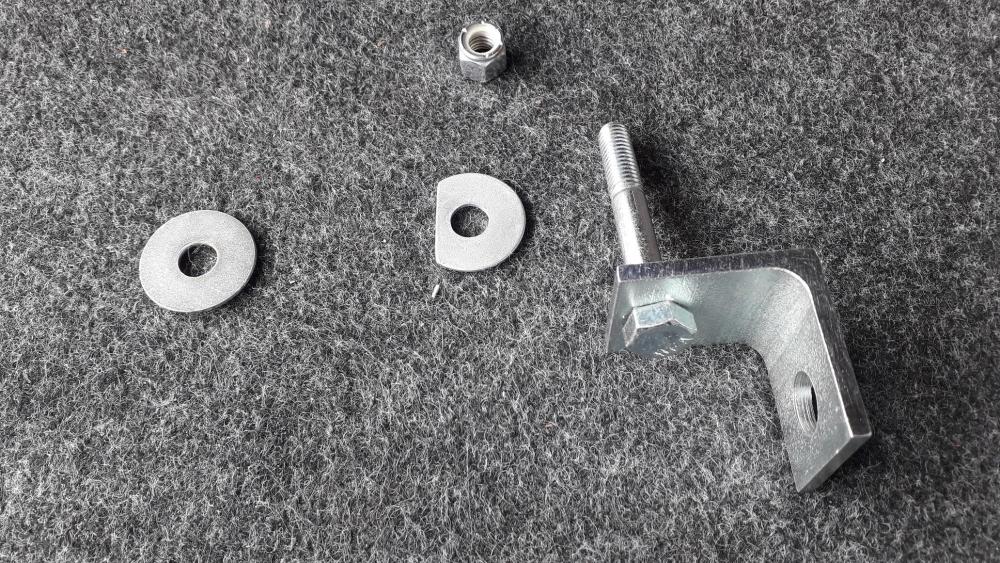
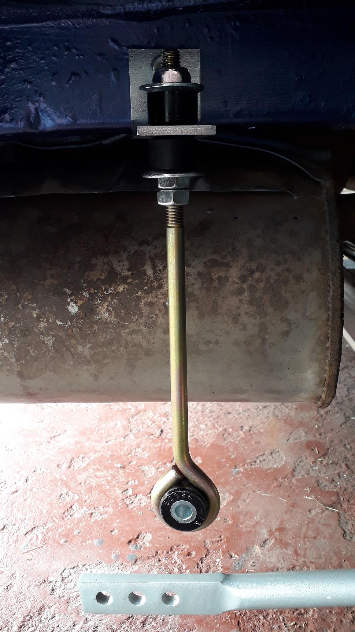
On the drivers side I made a D- shaped washer to fit on the rear face next to the exhaust bracket to bring it all to the same level as the exhaust bracket. Then I attached the large washer and nut to fasten the chassis brackets.
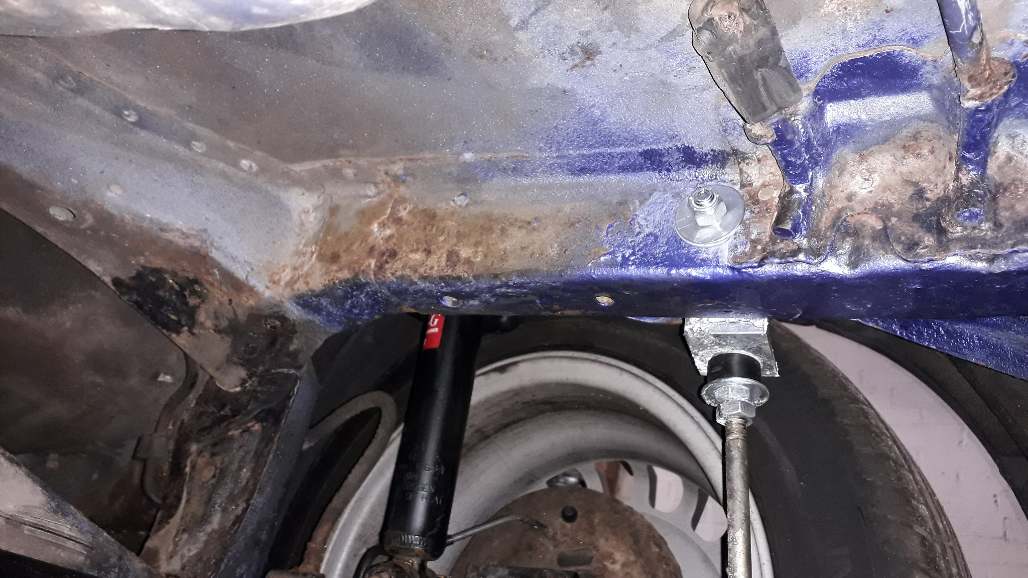
Brackets mounted both sides. Don't over tighten as the metal sections are quite soft.

Drop links attached, again don't over tighten as the rubbers are soft. I set the length so the arb arms were close to horizontal but slightly higher at the adjustment hole end. Then attached the drop links to the central hole using the bolt, 2 x washers and nylon lock nut provided.

All done, wheels on and back on the ground.

All in all a good product. Will improve handling and is adjustable to suit different suspension setups, cheap and relatively easy to fit. The down sides are for a road car you lose 50mm of ground clearance. Can't jack up the car under the rear beam anymore. If I was doing it again I would probably look into welding the chassis brackets to the chassis rails instead of bolting as this would allow free placement on the drivers side. Also the rear face of the passenger chassis rail is angled so the nut doesn't sit flat. Not a problem just looks weird, might "dress" the area flat if it bothers me in the future.
Please with how it came out.
-
25 minutes ago, Starletson said:
Swapped the throttle bodies and everything back to normal 😁
Good times 😎👍
-
14 hours ago, Sam44 said:
Your welcome.
Big fan of your build. Im striping an early 4efte head at weekend to port and polish it. If your interested in the valve springs.
Thanks for the comment. Don't need the valve springs though. Cheers
-
On 4/15/2019 at 7:51 AM, Dean_mc88 said:

Very neat. I like it.👍
-
Bought a GT thermostat housing. As described, good price and fast delivery.
-
+2 from me. Bought a couple of things, both arrived as described in good time.
-
13 hours ago, RoyalDutchie said:
verifying your email address should make it possible to send and receive pms.
Strang maybe pm an admin or mod about this.
Thankfully I can PM the admin team and they're looking into it.
-
25 minutes ago, RoyalDutchie said:
Cosworth seems to go to 1.5 bar right. Mishimoto is also an option for 19 psi or 28 psi rad caps for about 23 euro's including shipping.
note:
verifying your email address should make it possible to send and receive pms.
Thanks mate,
Think I've verified my email, I can send PM's to some members but not others. I'll try yours.
Edit: Nope!
-
1 hour ago, Sam44 said:
Urmm nothing mad about it.
It's quite simple it's the same system, you just use the radiator to help maintain block pressure. This is how most other engine manufactures work.
I take it you aren't aware of the pressure cap problems at high rpm and temp. (Track action).
A very valid point of filling the system. I always use pressure\vacum to fill the system and test for leaks, but as you have pointed out if you fill by hand there is a potential for an air lock if filled in a hurry and not bled threw.
The coolant flows from The water pump to the engine block, threw the block to the cylinder head using the head gasket coolant ports located exhaust side (hot valve side) located only on cylinder 1&2 (furthest side away from thermostat side\block exit) block exit located on the gearbox side\cyl 4 side of the cylinder head. it then supply's the top radiator hose (large bore diameter), heater matrix inlet also provides the throttle body thermostat idle control valve on this line, turbo coolant inlet, and if the thermostat is closed/not at temp a very small diameter bore bypass port back to the pump (all incorporated in the thermostat housing) With the thermostat closed there will be no circulation threw the radiator but the top hose & pressure cap see engine pump pressure at all times.
All proformance engines run a constant 30psi block pressure to stop air bubbles forming, but factory cap pressure is .9bar this is why they fail and spray coolant everywhere on track. Block pressure overpowers the cap to the point the main seal fails.
I hope this helps understand the unusual Toyota e series design.
Now if we switch the radiator hoses around the bottom hose now becomes high pressure side (engine pump/block pressure) and the top hose/rad cap low pressure side. Until system is upto temp. Eliminating pressure cap issues and helping stabilizing block pressure.
I guess that why they offer higher pressure rad caps like 1.2 bar etc.
It looks from your description of the system that I understand the coolant flow when hot and cold.
My only concern was that in swapping the hoses at the thermostat this reverses the flow through the radiator when the system is up to temp. The top hose thermo housing outlet is now attached to the bottom hose feeding hot coolant into the bottom rad tank and the bottom hose thermo housing inlet is now attached to the top of the rad. The coolant flows from bottom to top now, I think I'll leave it as Toyota intended.
-
That's weird? when I unplug my icv connector when warmed up it raises the idle! As far as I know the valve defaults to an open position which raises idle rather than oscillating the valve.
Is it the icv from the new replacement engine? maybe its stuck and not adjusting with the coolant heat. Do you have the old icv from the original engine you could try?
-
22 hours ago, Sam44 said:
Yeh the rear of the thermostate is block side or high pressure side a minimum of 2bar pressure should be maintained block side at all times.
the shear fact of the top radiator hose and pressure radiator cap are also on the block side is the first warning signs with the factory radiator cap set at ???psi. This is why at high rpm (track use) and high temps we see the rad caps covering the engines in coolant. Bad position.
Infront of the thermostate is radiator side or low pressure side this then dictates the flow direction as well as using water pressure to cool the turbo (packing the water molecules tight/close together) this allows for fast heat transfer and stops bubbles forming in the turbo coolant jacket. Air acts as an insulating layer stoping the coolant removing heat. Pressure stops this happening.
In all honesty the E series and A series coolant design is poor to say the least using a weak pump and bad flow paths.
Another good mod is to swap the hoses round to the radiator, this stops the pressure cap problems we see on track and helps maintain block pressure, using the narrow core of the radiator to maintain block pressure thus eliminating pressure cap problems.
Do you need anything else I've got ep91 and ep82 parts coming out of my ears, I've got a powersteering pump but not the 2xpipes that are needed also.
I would have thought the overflow bottle would have been ok at containing the expanded coolant escaping from the radiator through the cap or I fail to see the function of the bottle at all?!
Also if I understand correctly the coolant flows from the block to the back of the thermo housing, through the bypass hole and back down the tube behind the engine to the water pump and then into the engine. The coolant heats up, opening the thermostat and closing the bypass hole (or slowly fluctuating to increase flow through the radiator.).
So coolant now flows from the block to the back of the thermo housing, through the top hose (as bypass is closed), to radiator and out the bottom hose back into the side of the thermo housing through the newly opened thermostat and back into the engine via the tube behind the block to the water pump when warm.
If you swap the hoses at the thermo housing won't you be filling the radiator from the bottom now? With water exiting the top of the rad? Not sure the pump has the power for that. Also does it not increase the risk of air being trapped in the system? By all means give it a try and report back, you seem to be the forums resident mad inventor! lol😃
The way I look at it more mods = more potential issues. Minimal changes to get the best acceptable outcome. Keep it simple ......


.jpg.02983778a8713abdf5b328772753c07a.jpg)


EP91 Build
in EP91 Progress Blogs
Posted · Edited by Claymore
Apologies for the mini hijack
Just because it made me smile really
The channel has some other interesting vids to do with bell mouth shape and design also.
Last pic of my favourite itb intake manifold. 50mm slide throttles, carbon fibre 8 injector airbox from Tim Harvey's Labatts M3