

RobSR
-
Content Count
4744 -
Joined
-
Last visited
Content Type
Profiles
Forums
Wiki
Media Demo
Store
Calendar
Posts posted by RobSR
-
-
You need 1 input and 1 output for the A/C, outputs won’t be a problem but inputs can fill up relatively quickly on the monsoon if you start adding a lot of additional sensors.
If you were looking at EMU I’d go black not classic, Link Monsoon you could just about do it, or look at a Storm or even Haltech Elite
-
On 11/25/2023 at 1:16 AM, Frankieflowers said:
I was wondering if there are base map files for the MonsoonX Link for 4efte ep91. I hope that someone can help. P.S. is there a way to read a stock fte ECU?
I have my own basemaps, Link don’t supply one for 4E
No I don’t believe anyone can read a file from the stock ecu
-
On 9/6/2023 at 3:11 PM, shorty said:
This looks soo good! 🤤
Cheers!
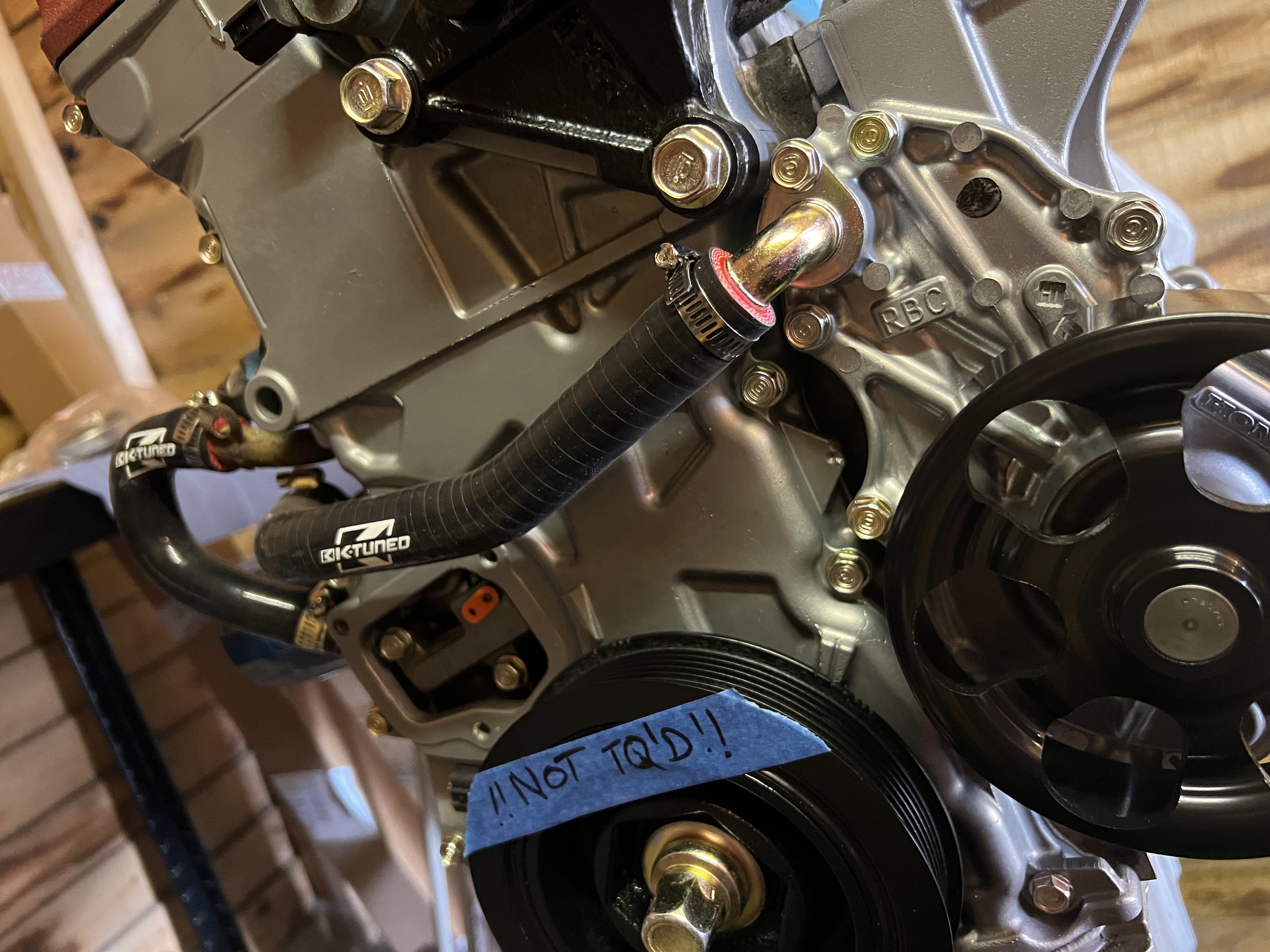
Doing some of the plumbing at the moment. Few more bits to do on fuel lines and vac lines then that’s complete too.
-
Progress has been good, hopefully in a position to start it next month
-
Nice work going on here 👍
-
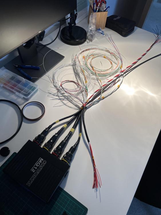
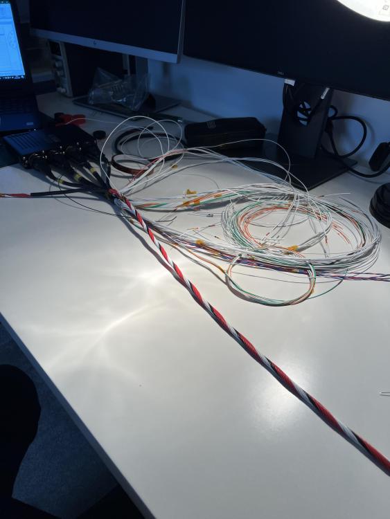
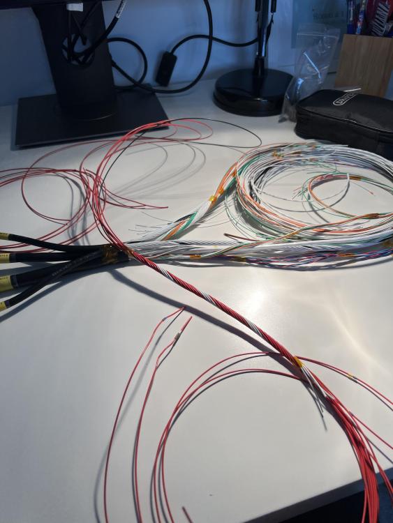
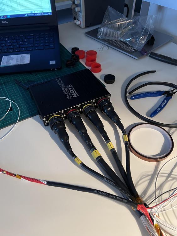
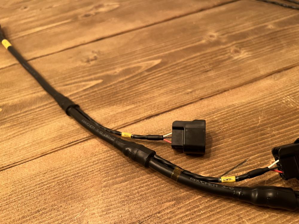
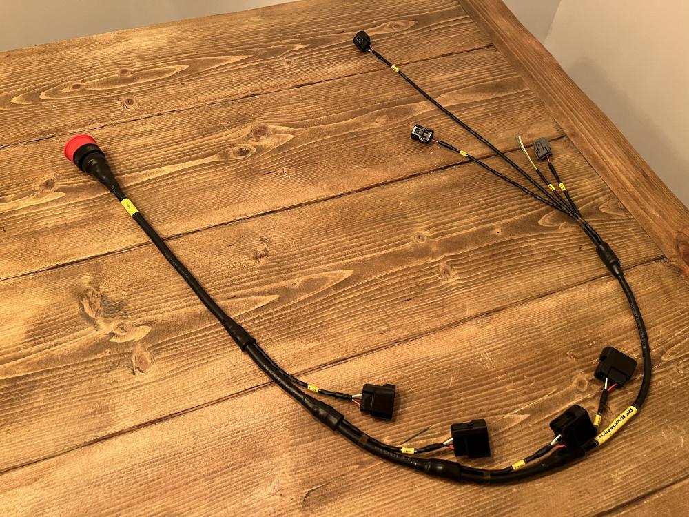
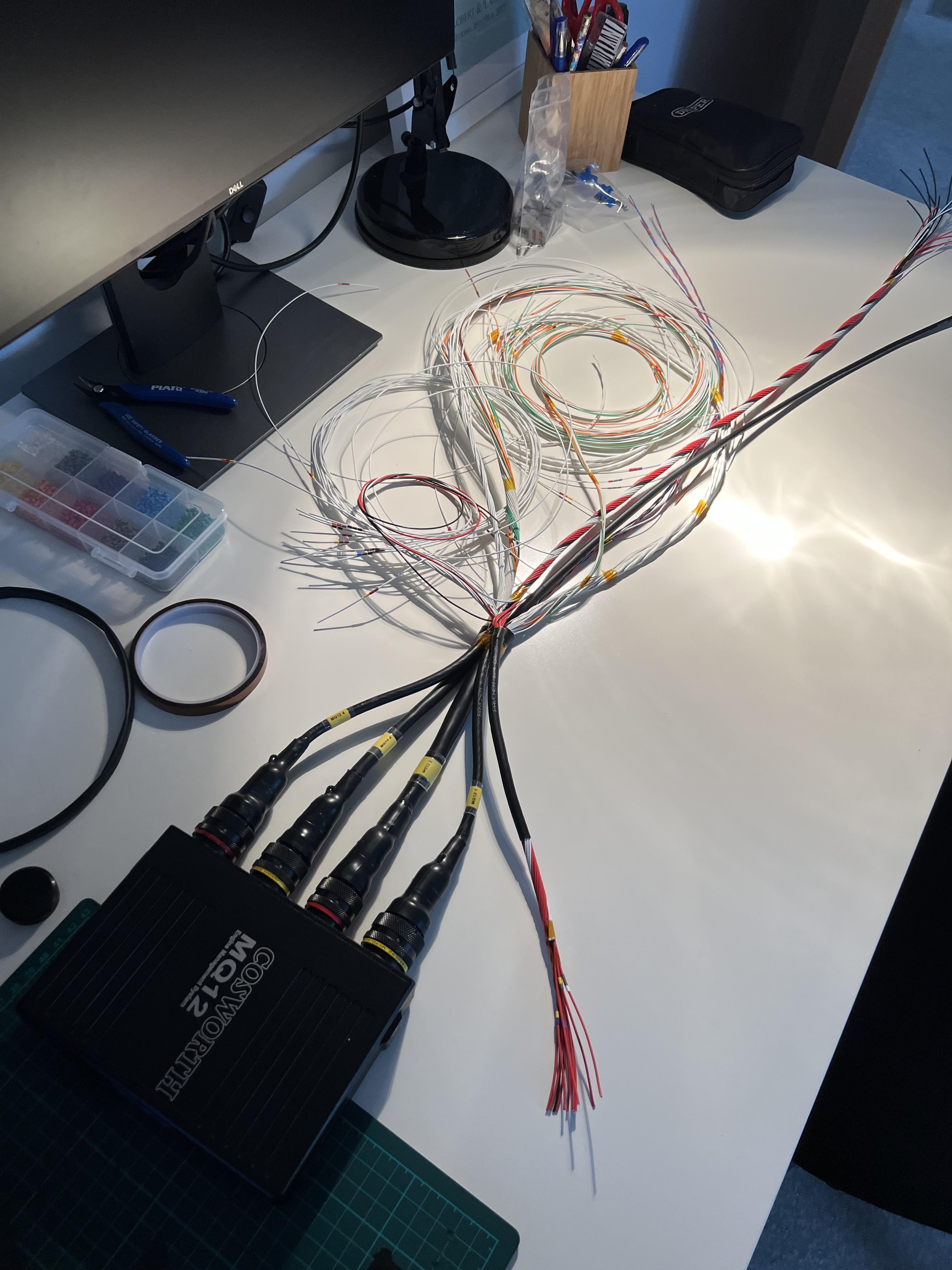
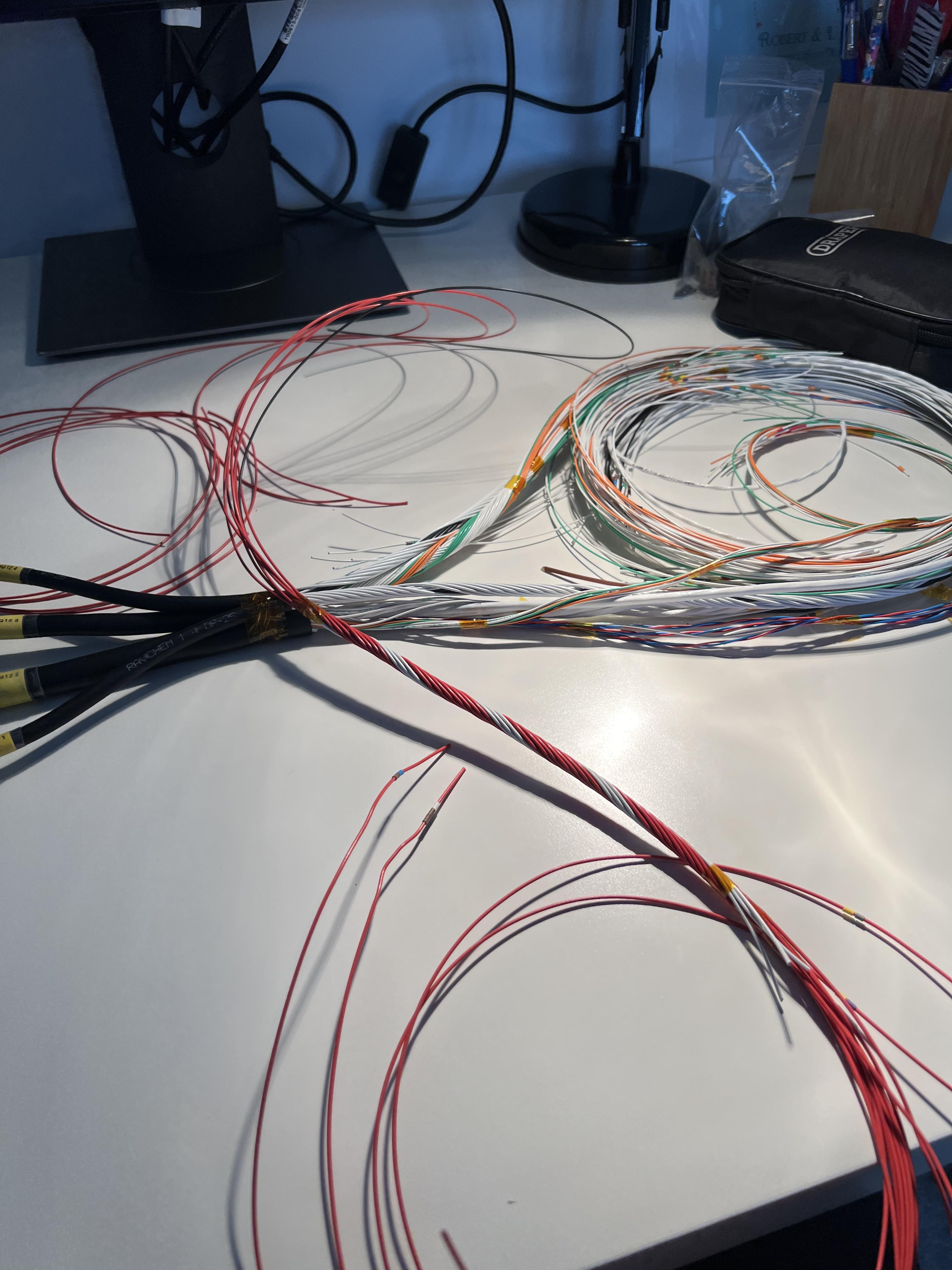
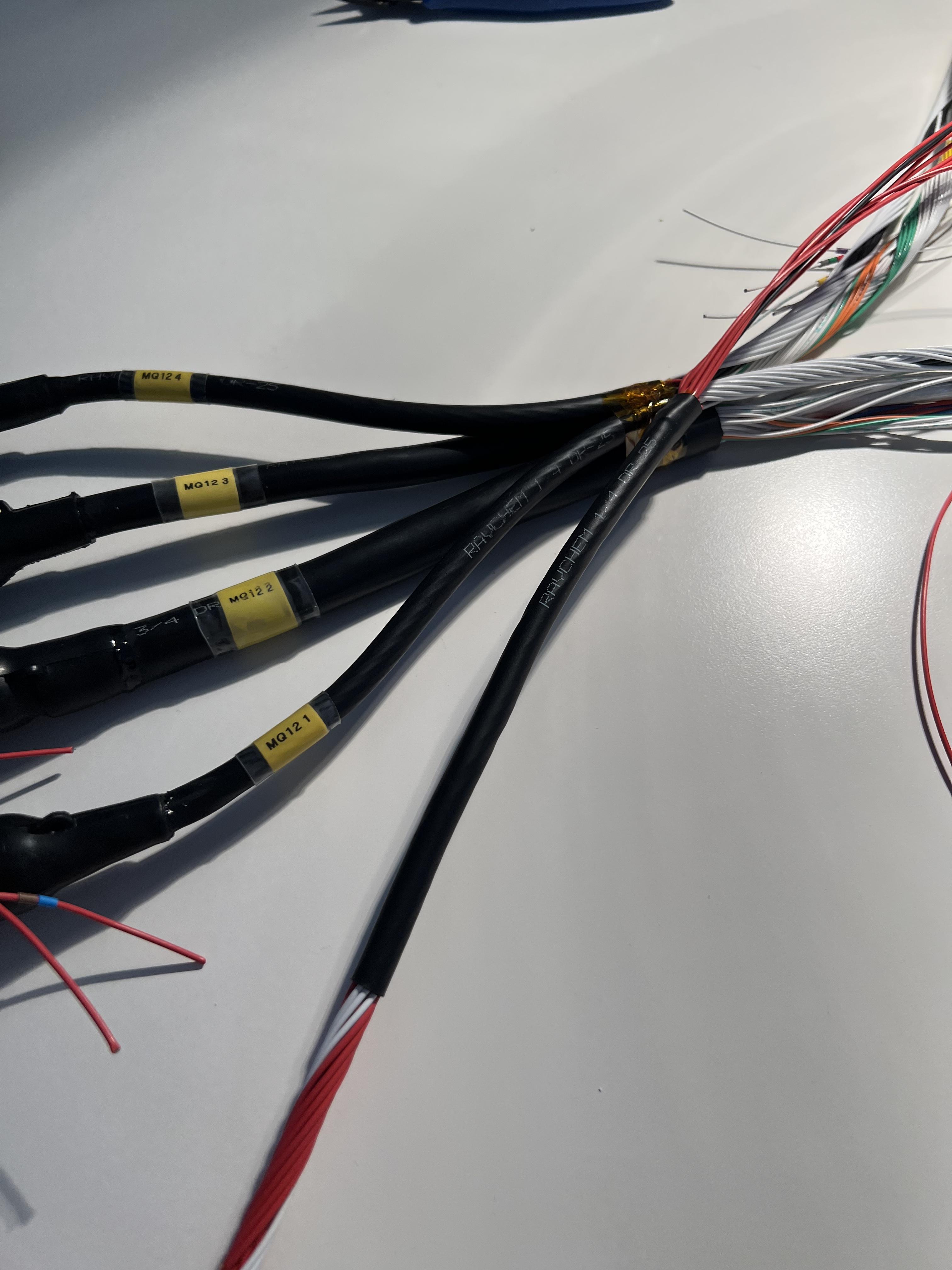
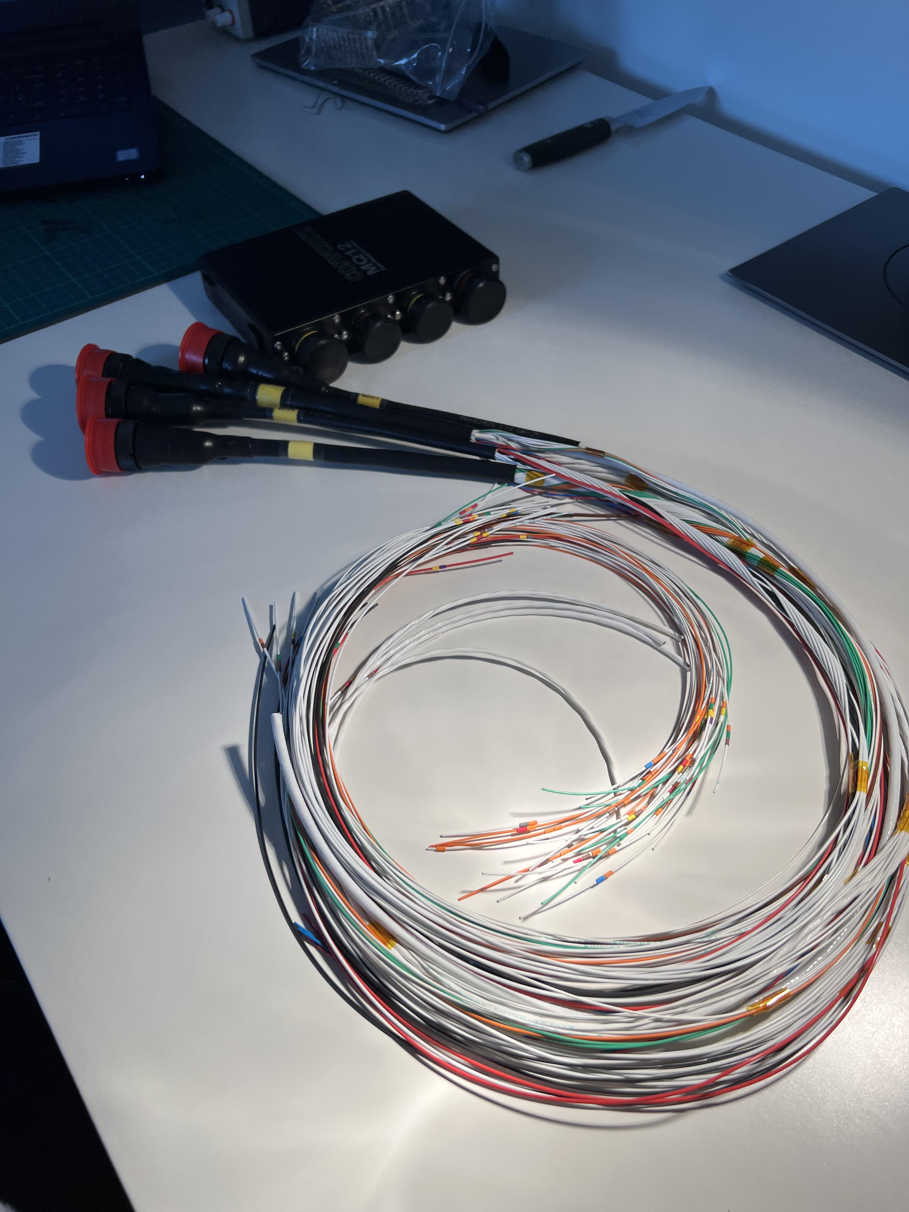
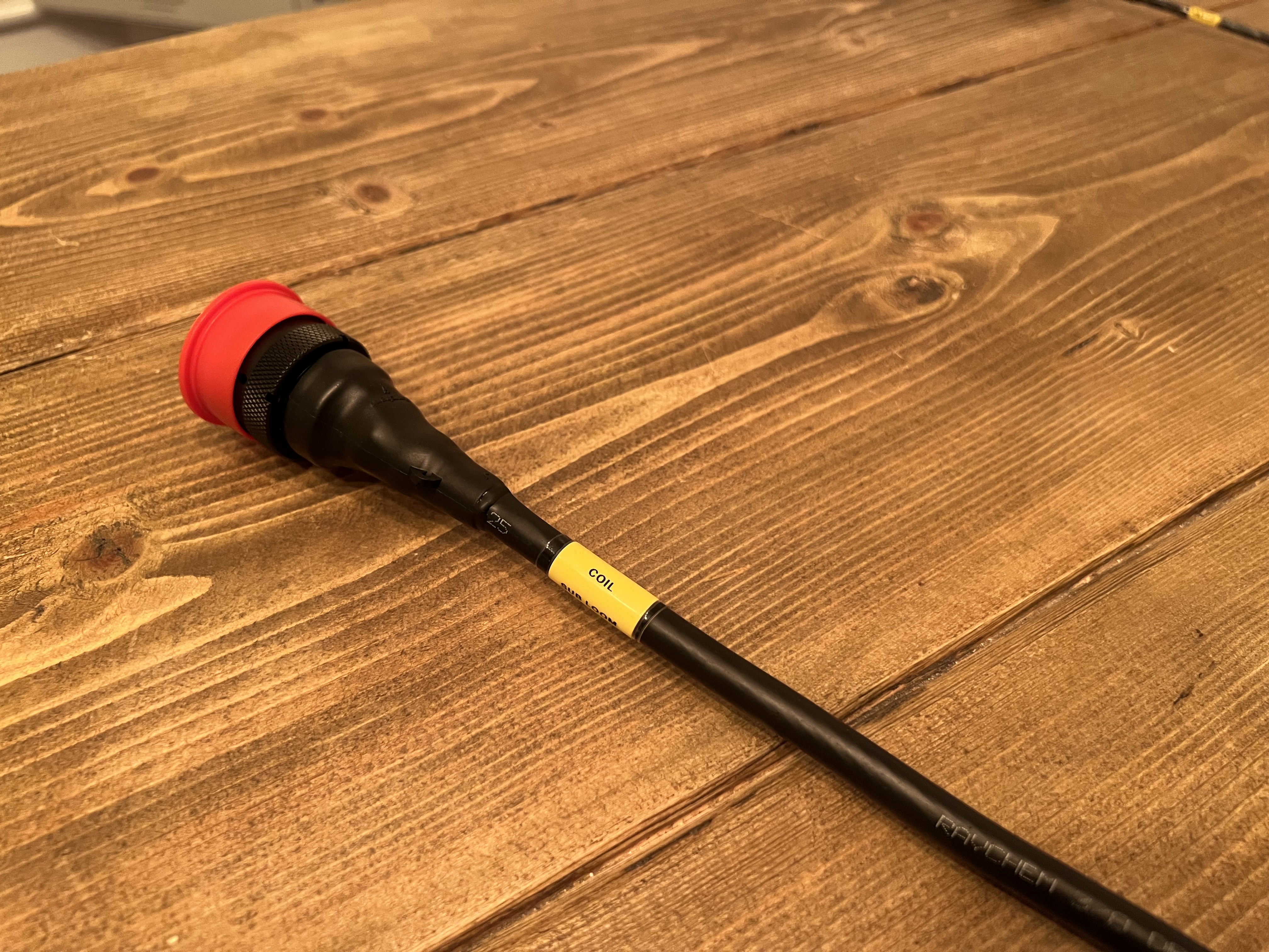
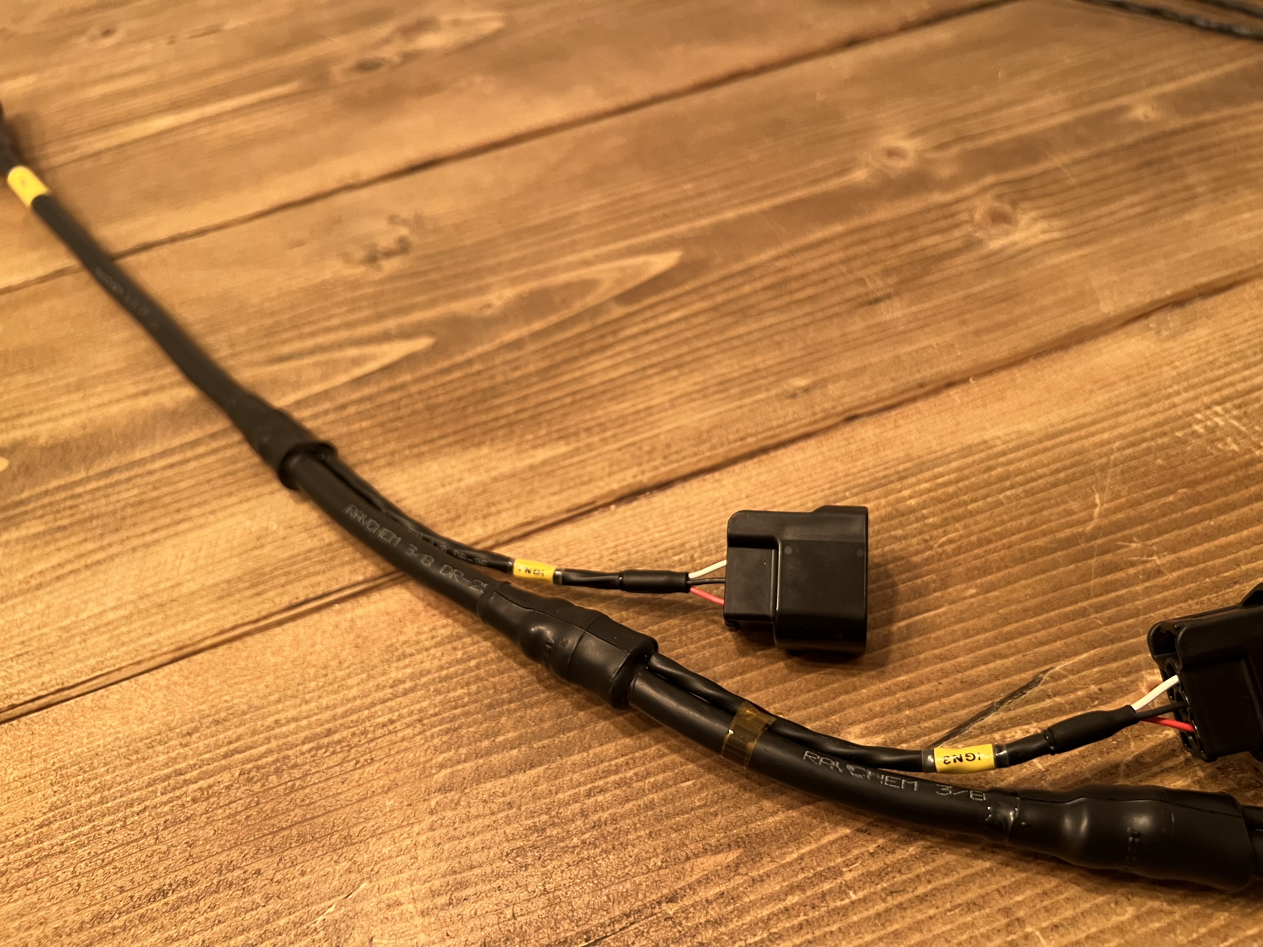
The next wiring headache underway


-
-
On 3/14/2023 at 10:47 PM, snails ep91 said:
So Good! keep the updates coming
Thanks!
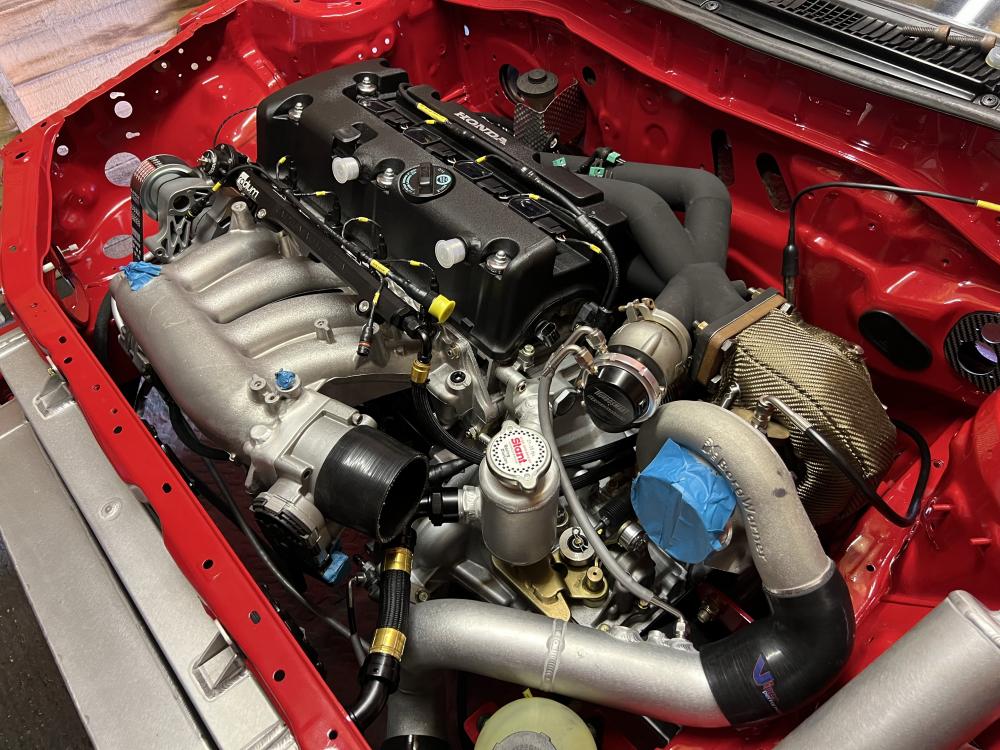
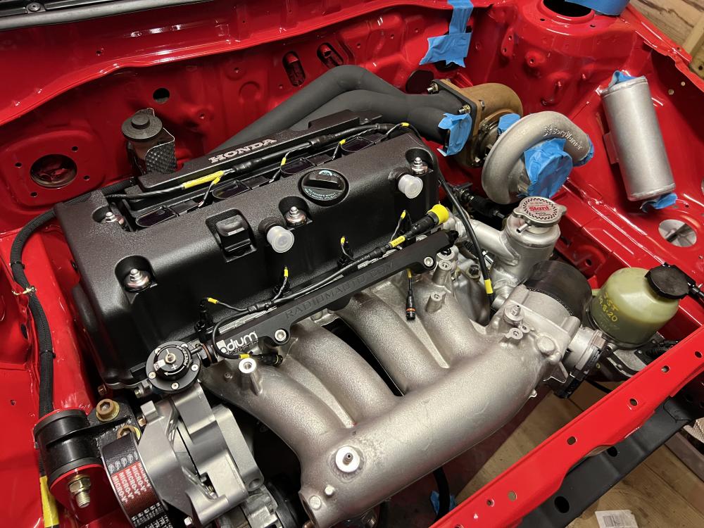
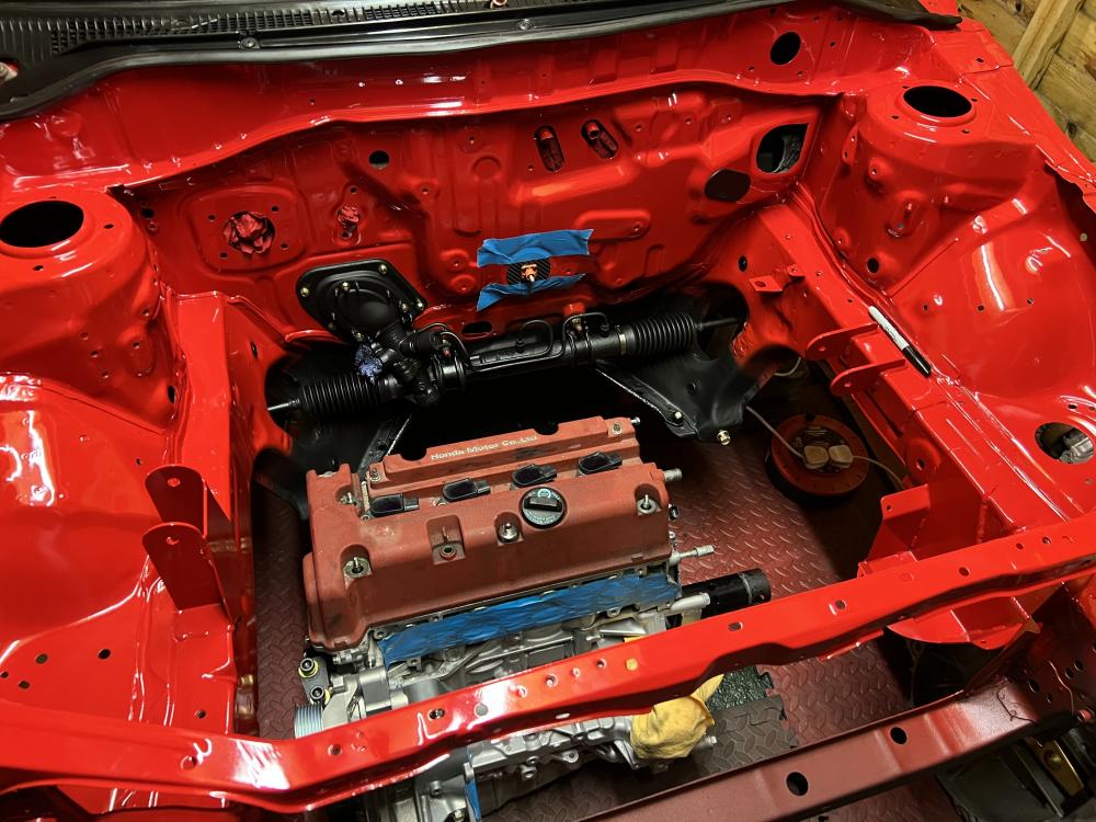
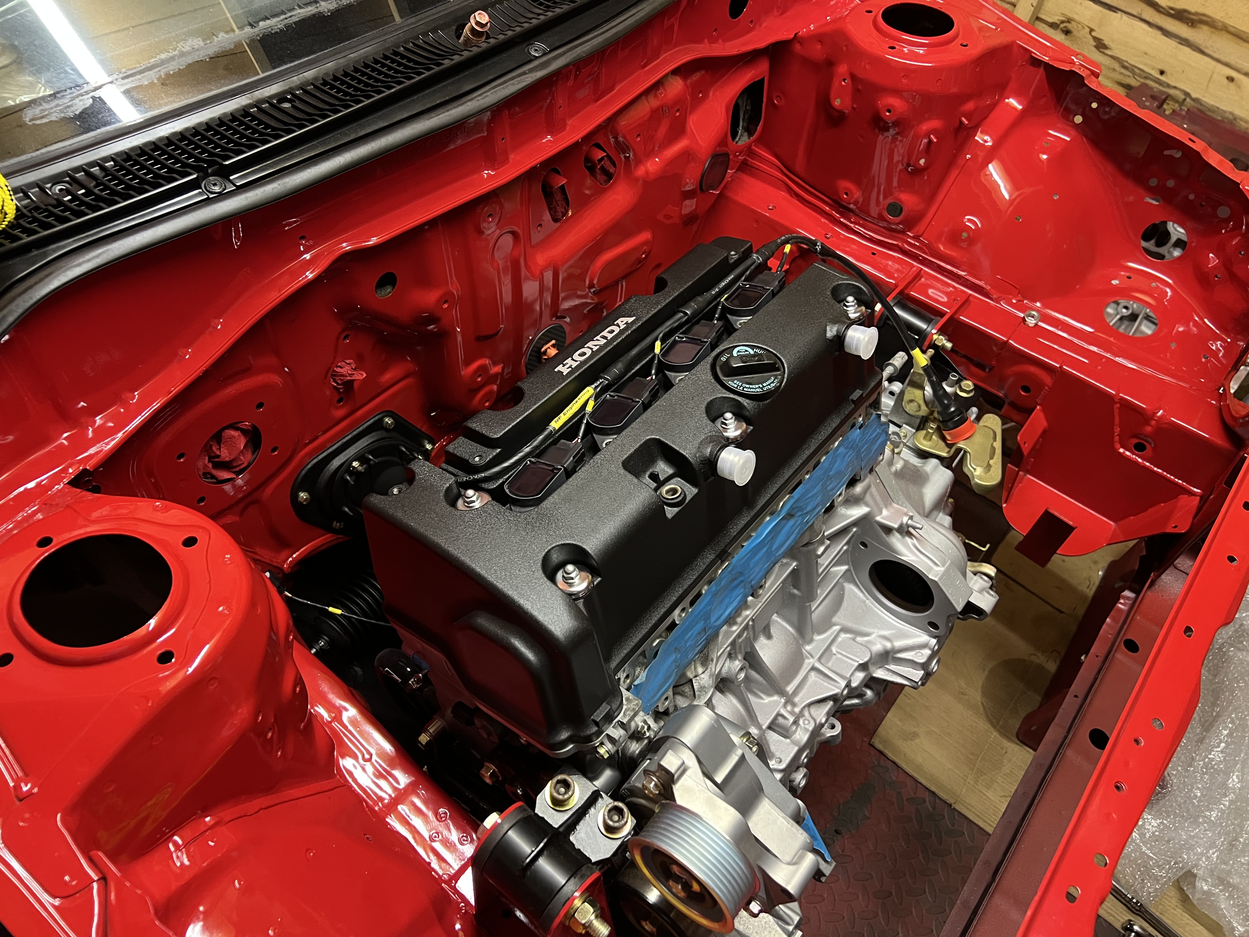
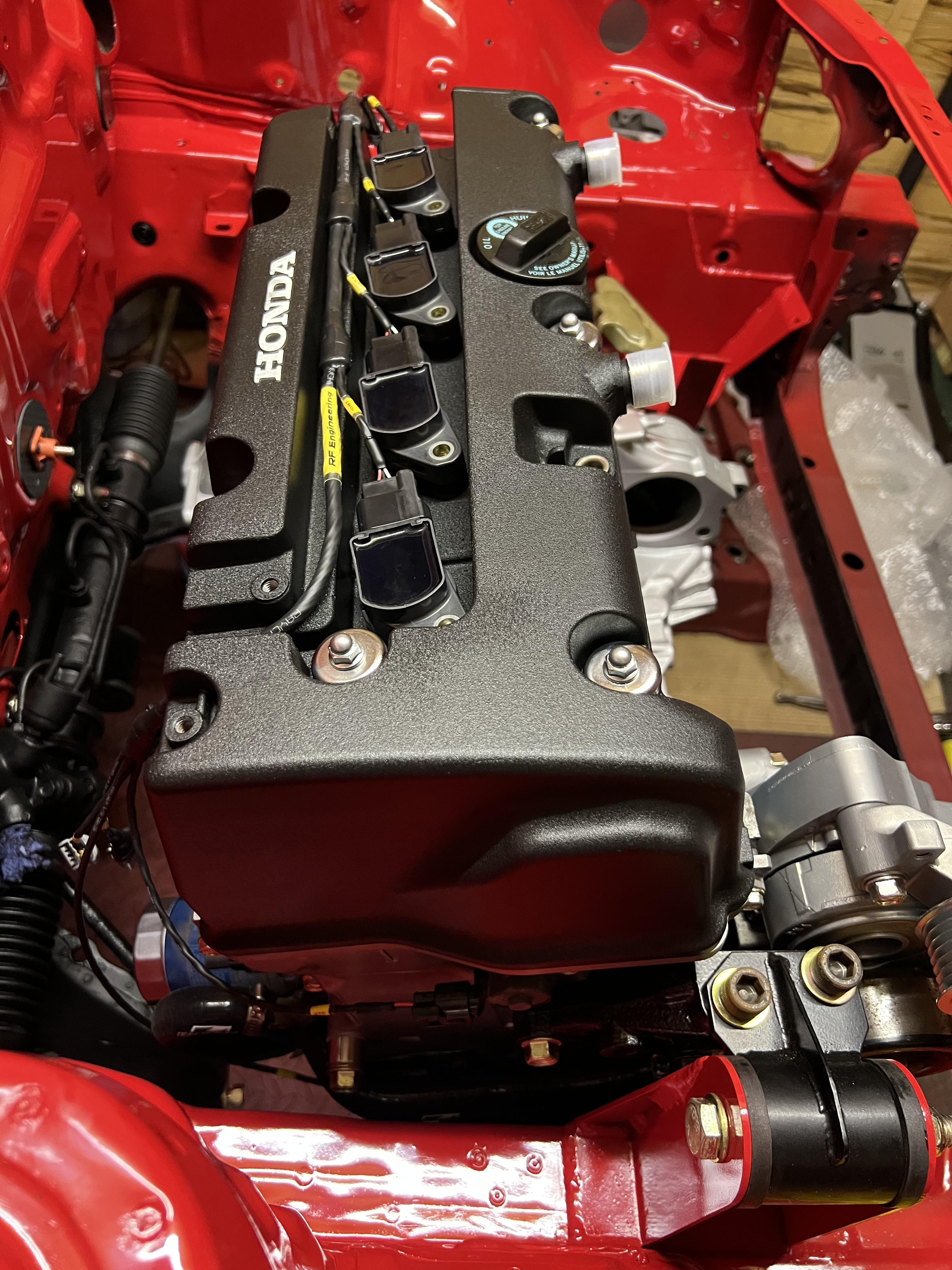
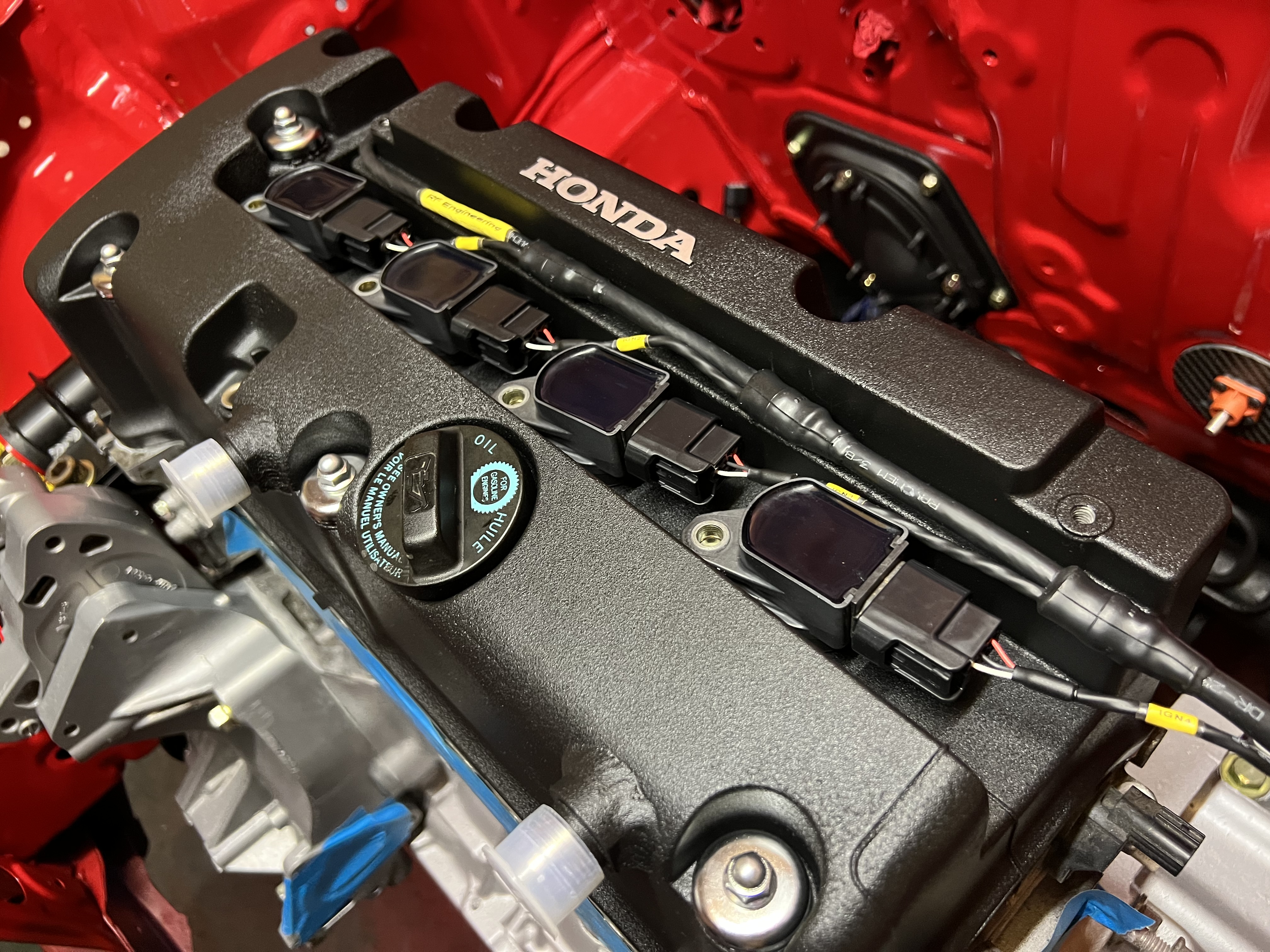
It’s mounted back in for good now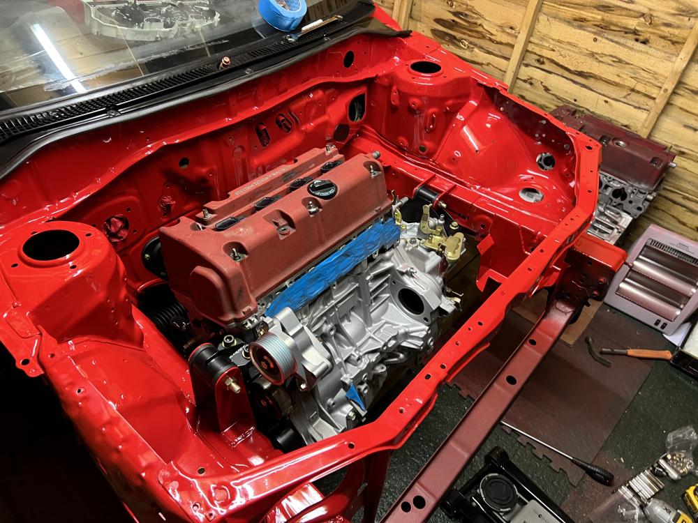
-
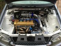
Ready to go back in for good now! All the engine work is done, got the majority of parts vapour blasted or painted and all the old bolts re-zinc plated too
Refitting with temporary cam cover so I don’t accidentally smash the new one to bits lol
-
Have been trying to make some videos of the build too:
-
On 2/3/2023 at 10:48 PM, Thonfella259 said:
🤌🤌🤌🤌 sweeet build
On 2/2/2023 at 2:27 PM, shorty said:That looks sweet as!
Thanks all!
-
On 2/1/2023 at 6:13 AM, jiggaman_16 said:
Hey Rob, any updates?
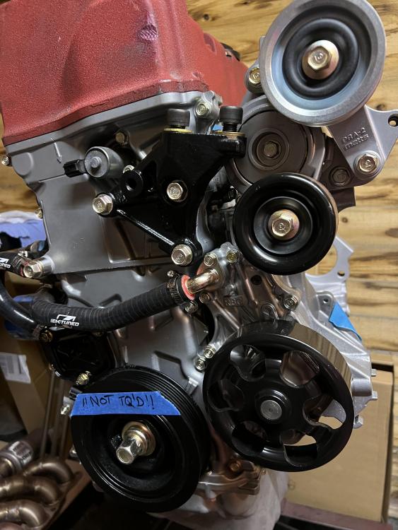
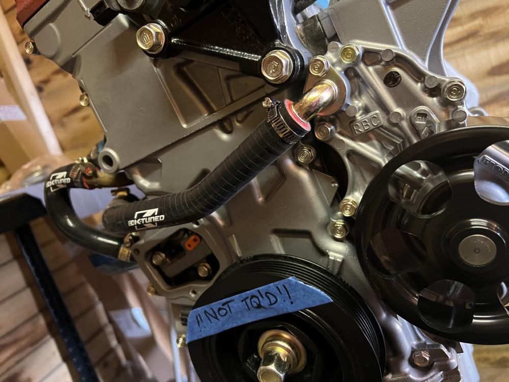
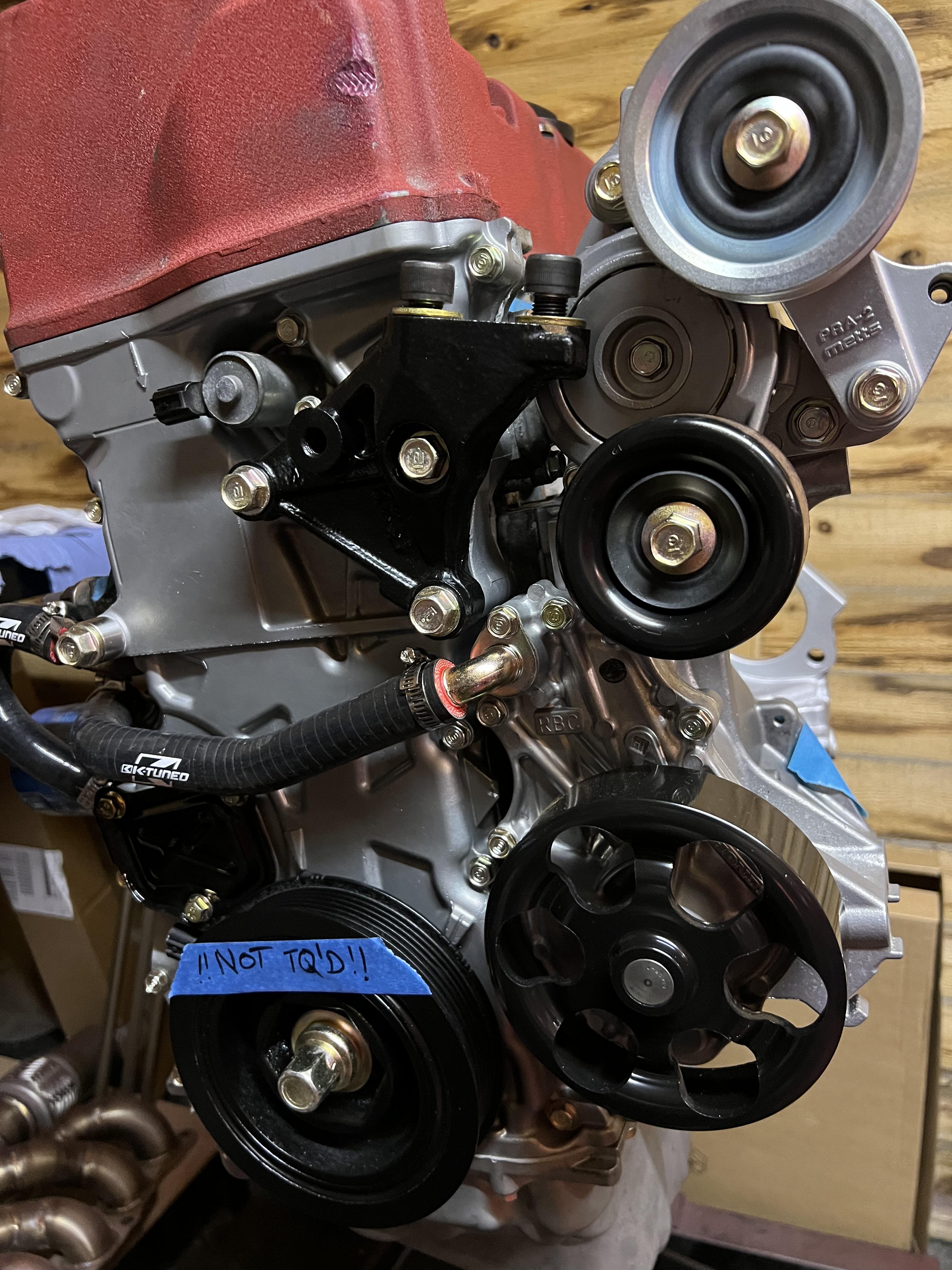
Mostly boring stuff! Loom work, engine bay painting, new oil pump and timing chain on engine etc etc.
Moving onto the brake kit next.. have to do some more work on the shafts also

-
I would not bother. There is no evidence the ‘airflow’ is better, there is no plenum which a turbo engine likes and the runners are designed the way they are for an n/a engine to help with low end torque.
-
Very few options for the autos. Probs easiest to get a Link or similar and fit it as a piggyback leaving the stock ecu to do the auto control
-
Nice updates 👍
-
Agreed that you can use the shield ground pin for that, but IMO you shouldn't be connecting any sensor grounds there. Hopefully Link have tied it into the PCB away from sensitive IC grounds and closer to power grounds but who knows. I probably over analyse but its good to have an understanding if you're really interested in it and reviewing/making your own decisions. Just because a couple of ECU manufactures do it a certain way, doesn't necessarily mean its correct.
If you're interested and have spare time, i can recommend watching this: https://www.youtube.com/watch?v=ySuUZEjARPY
Ricks whole career has been EMI problem solving and discusses exactly what we were talking about above. In short, his recommendation is don't connect your shield to your sensor ground lol.
-
Yes I’m really not sure why they recommend doing it this way, as you’re putting shield noise onto a pin all the other sensors are connected too.
All the big professional harness builders I’ve worked with who do stuff upto F1 level, put them to ECU/Power ground so I’ve always done it this way as I’ve had more consistent results.
Just my experience so thought I’d point it out
")
-
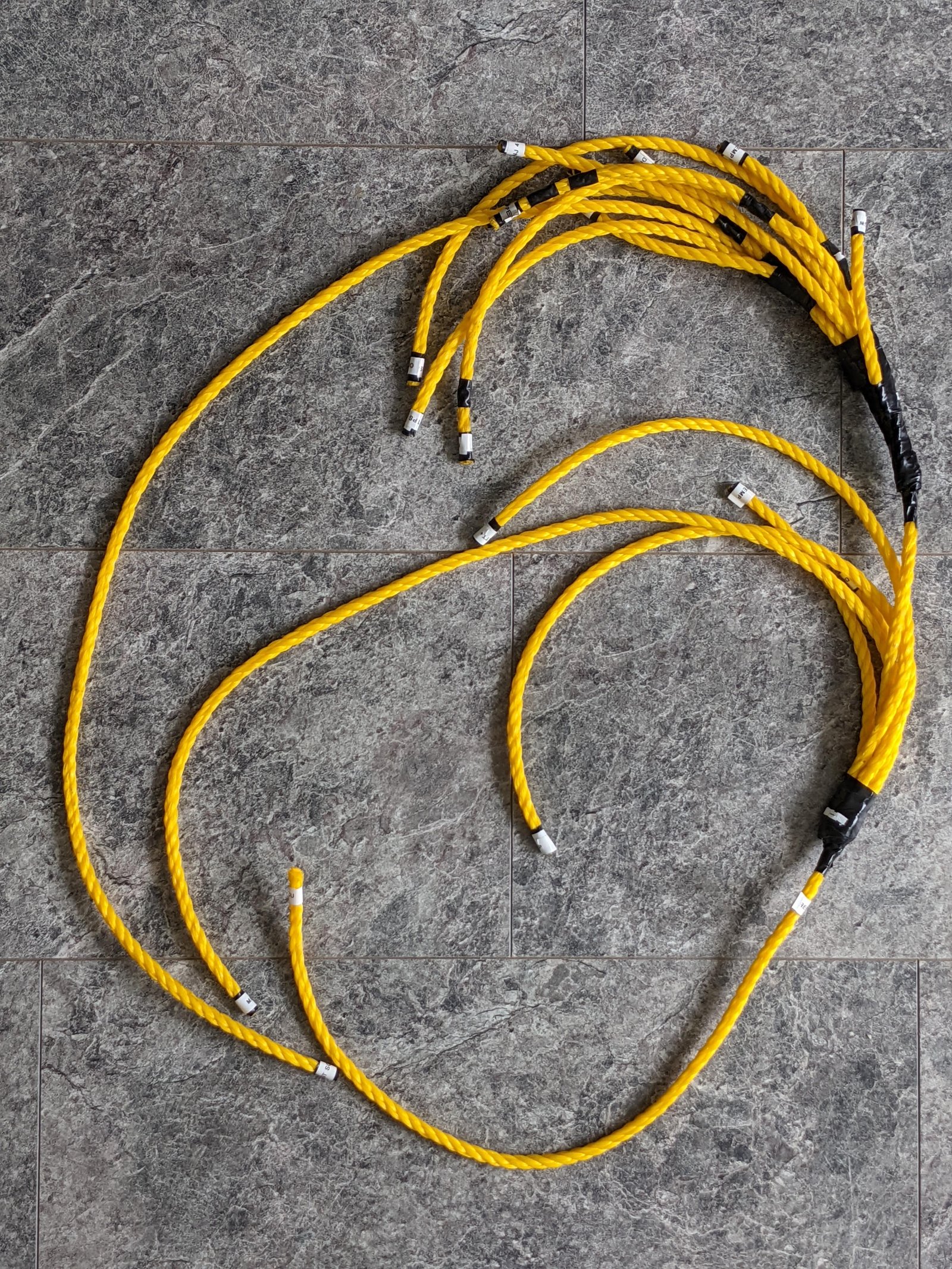
On 8/3/2022 at 4:26 PM, Patches said:
I made a mockup of my engine loom using rope
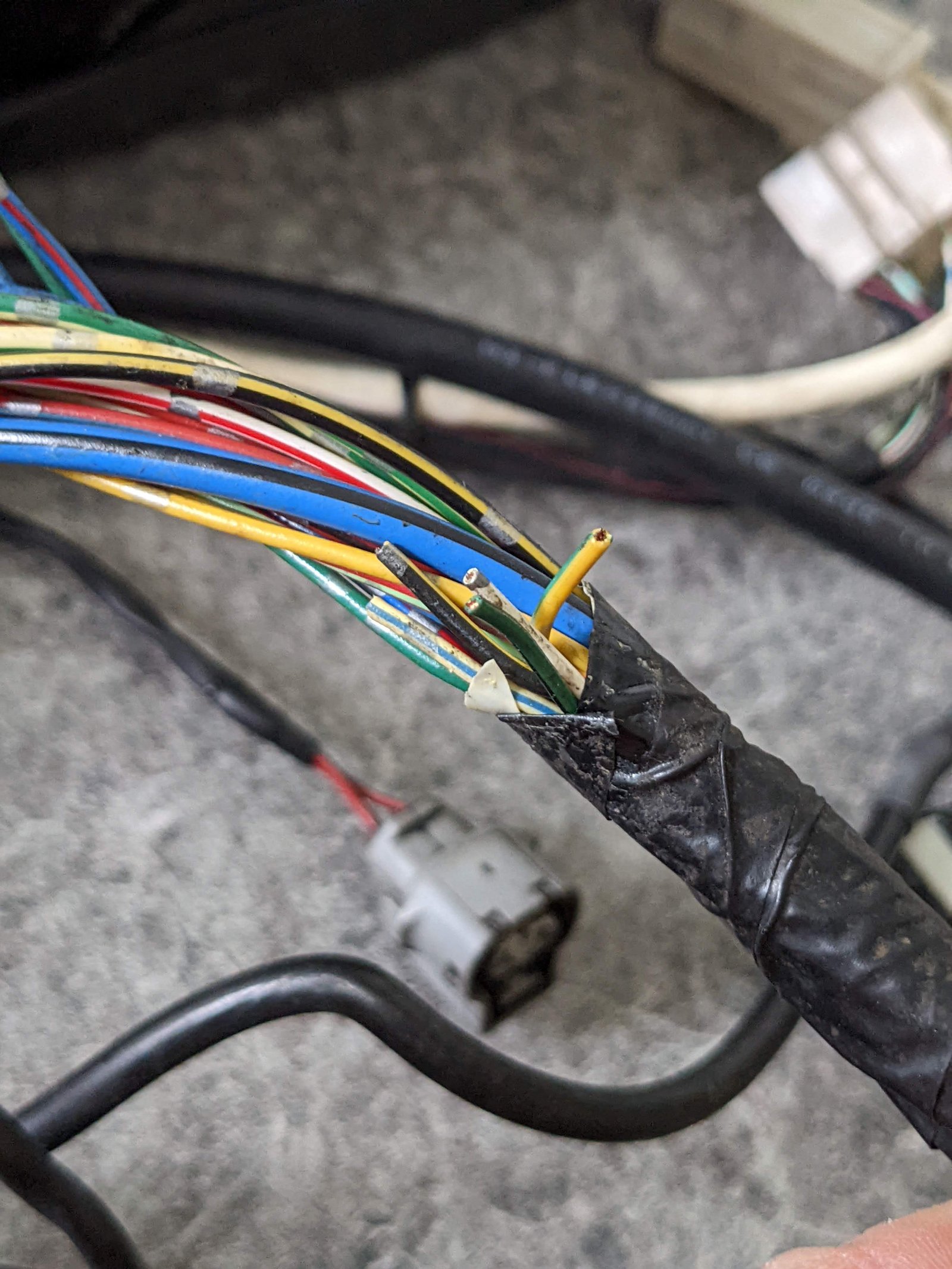
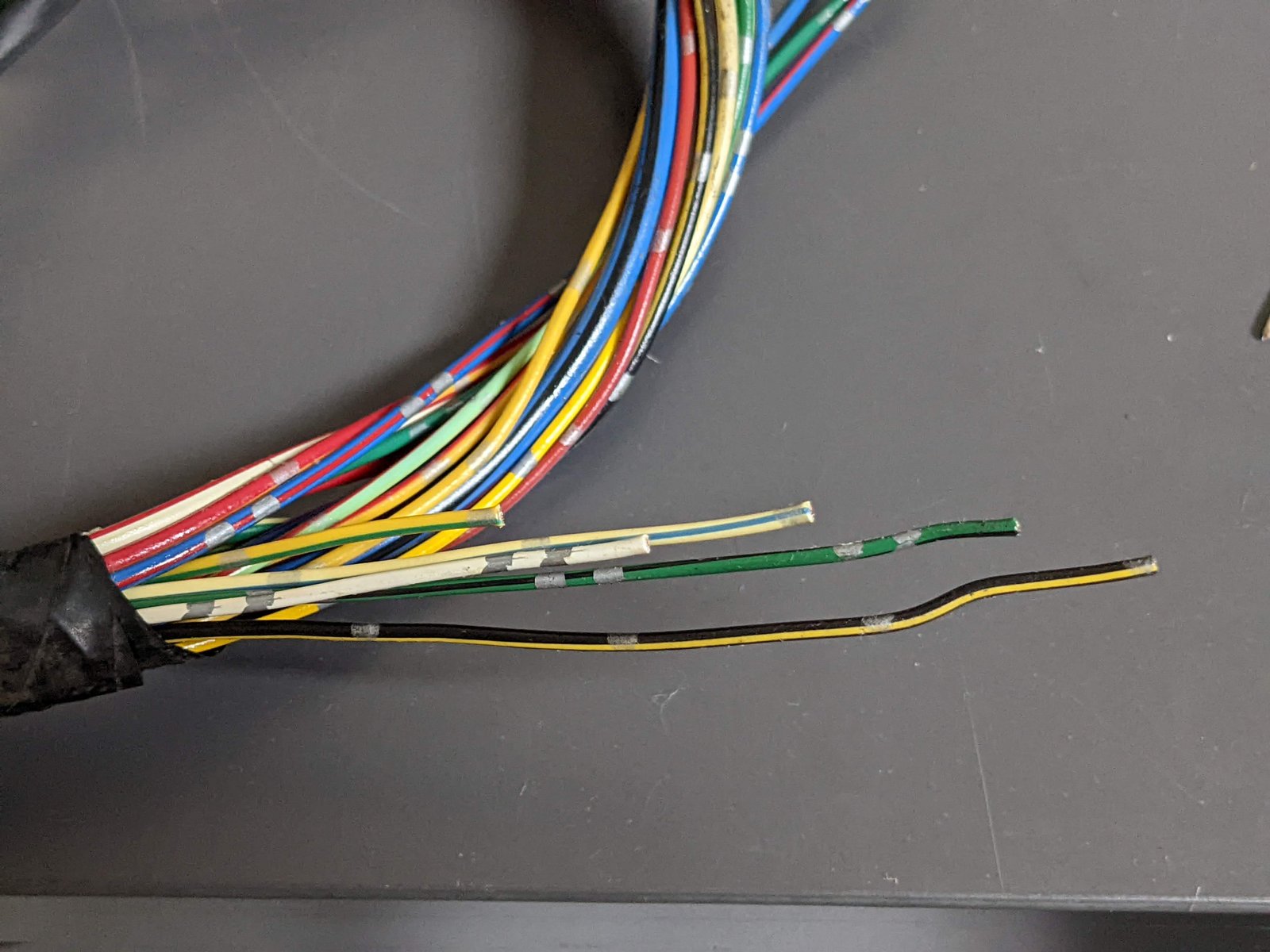
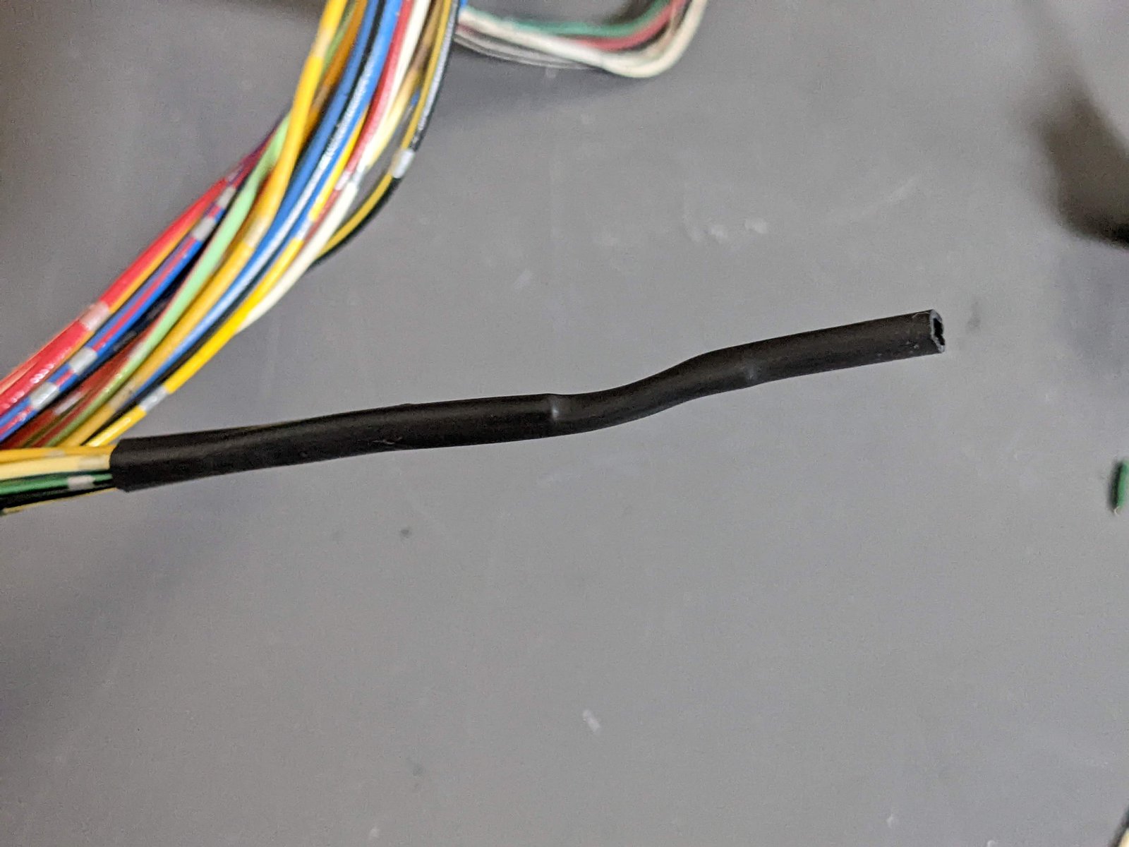
Found this hidden gem in the oem harness, not sure what it was originally for but the wires could have been touching each other so I've cut them at staggered lengths, covered with heatshrink and taped it up so at least its safe now
Here is the alternator, starter, windscreen wiper, reverse light switch and brake level sensor wiring fed into the AC blanking grommet, still need to terminate fan relay and a few other things on a dtm connector in the car

Repaired washer wiring, new terminals, heat shrink and cleaned the connector body as couldn't source a replacement

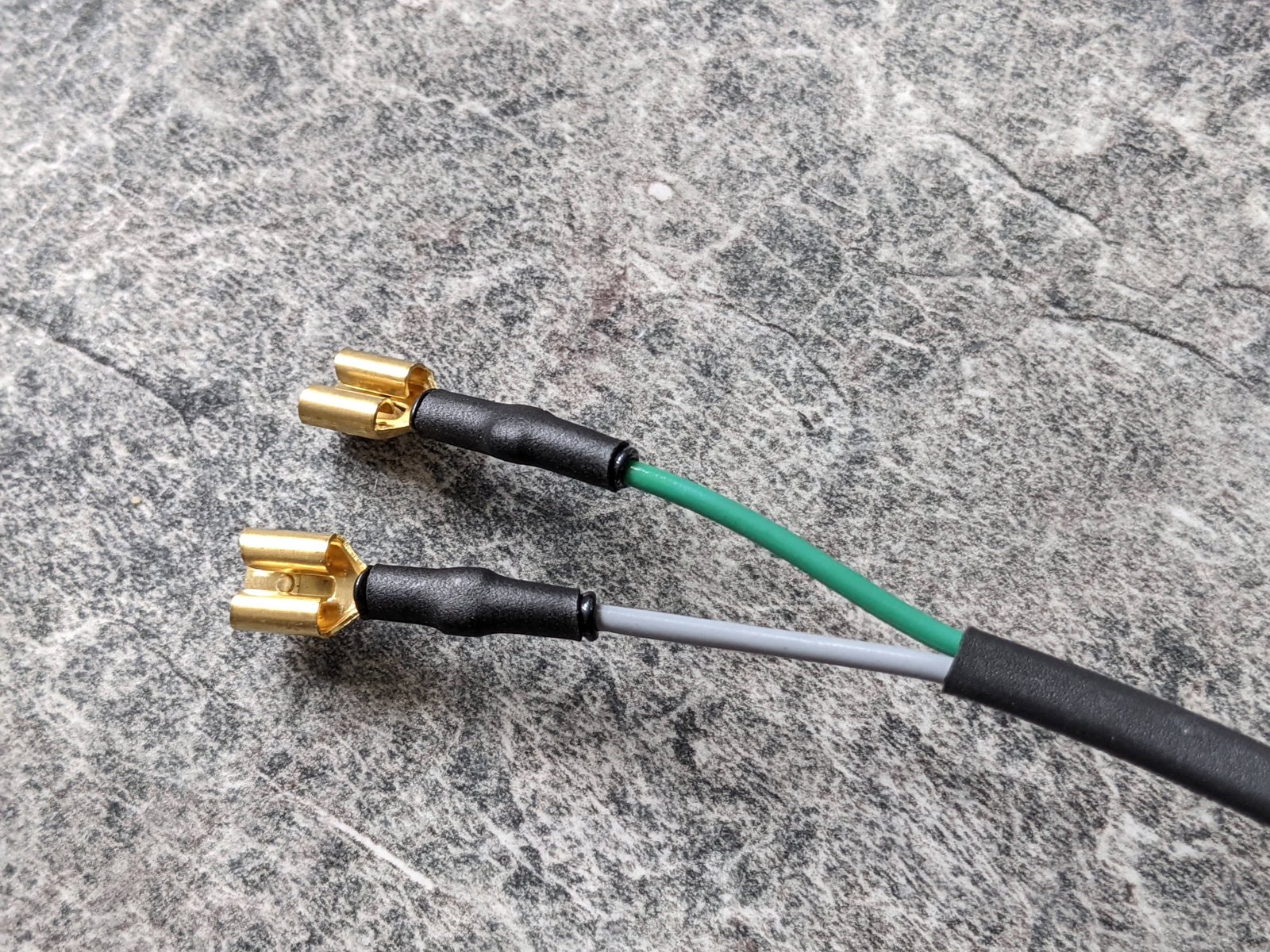
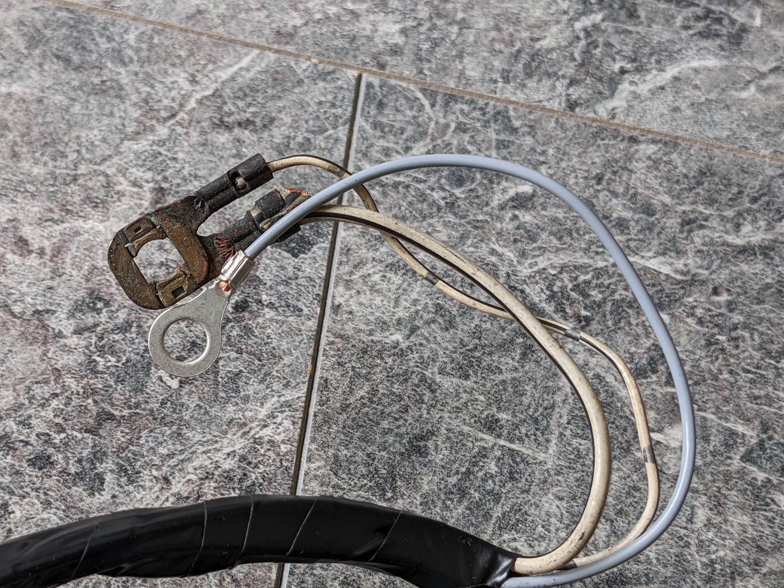
Remade my horn wiring, it will do the job. Ideally I would seal the terminals onto the horn and use new connectors but this should be fine.
New ground for the horn wiring
Knock sensor wiring, terminating the shield and one of the wires to a new wire for the sensor ground
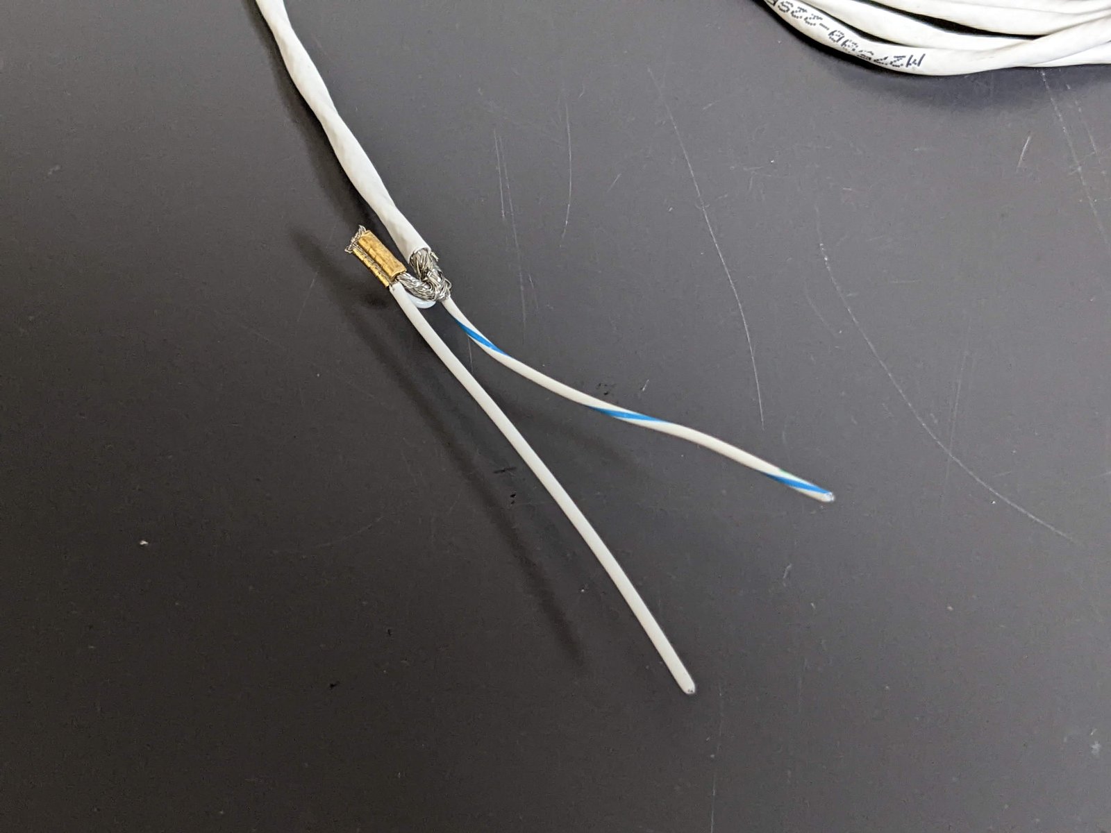

Just an FYI, on the knock you do not want to connect the shield and sensor ground together and then to the sensor ground pin.
conductors to Knock input and sensor ground, the shield should then be terminated on its own one end only to a chassis/power ground
-
Sorry, I can’t help I’m not a moderator / club owner.
It was Rob B that used to be but not sure anymore
-
Nice work!
-
Take the cluster out, look at the back and it shows all the PCB tracks so it’s pretty easy to work out
-
19 hours ago, Frankieflowers said:
We managed to refurbish the distributor. It works very well. The only thing that I still don’t understand is why the timing set to 10° doesn’t go to zero when taking the diagnostic bridge off. It goes the other way around 15° instead
So when you unlock the timing (by removing the bridge) your saying it doesn’t go to 0?
If so that’s normal, most engines idle at 15-20 deg
-
Yes a valid point by Sam to check your base cam timing too
-
You’d see the earth issue via the voltage in the ecu as injectors are on the same circuit
If fuel pressure is fine, it may just be an injector issue - it’s possible they may not actually be 550’s?
yes they should fit their own dyno lambda too so they can compare between the AEM reading; the AEM are notoriously unreliable however, I’ve seen them read a whole 1.0:1 either way than what my calibrated dyno lambda read.


K20 Turbo EP91
in EP91 Progress Blogs
Posted
There is yes but it was done for a Paseo so I think it needs some tweaking as one of the mounts is wider
I’ve developed a mount kit also as I’ve remade my bush carriers in billet so I may offer them for sale