RobSR
-
Posts
4744 -
Joined
-
Last visited
4 Followers


Recent Profile Visitors
18155 profile views


RobSR's Achievements
UKSO Elite (8/8)
-
There is yes but it was done for a Paseo so I think it needs some tweaking as one of the mounts is wider I’ve developed a mount kit also as I’ve remade my bush carriers in billet so I may offer them for sale
-
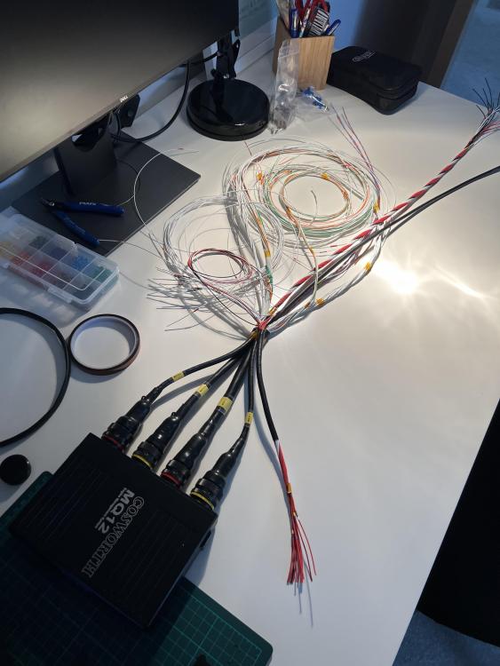
You need 1 input and 1 output for the A/C, outputs won’t be a problem but inputs can fill up relatively quickly on the monsoon if you start adding a lot of additional sensors. If you were looking at EMU I’d go black not classic, Link Monsoon you could just about do it, or look at a Storm or even Haltech Elite
-
I have my own basemaps, Link don’t supply one for 4E No I don’t believe anyone can read a file from the stock ecu
-
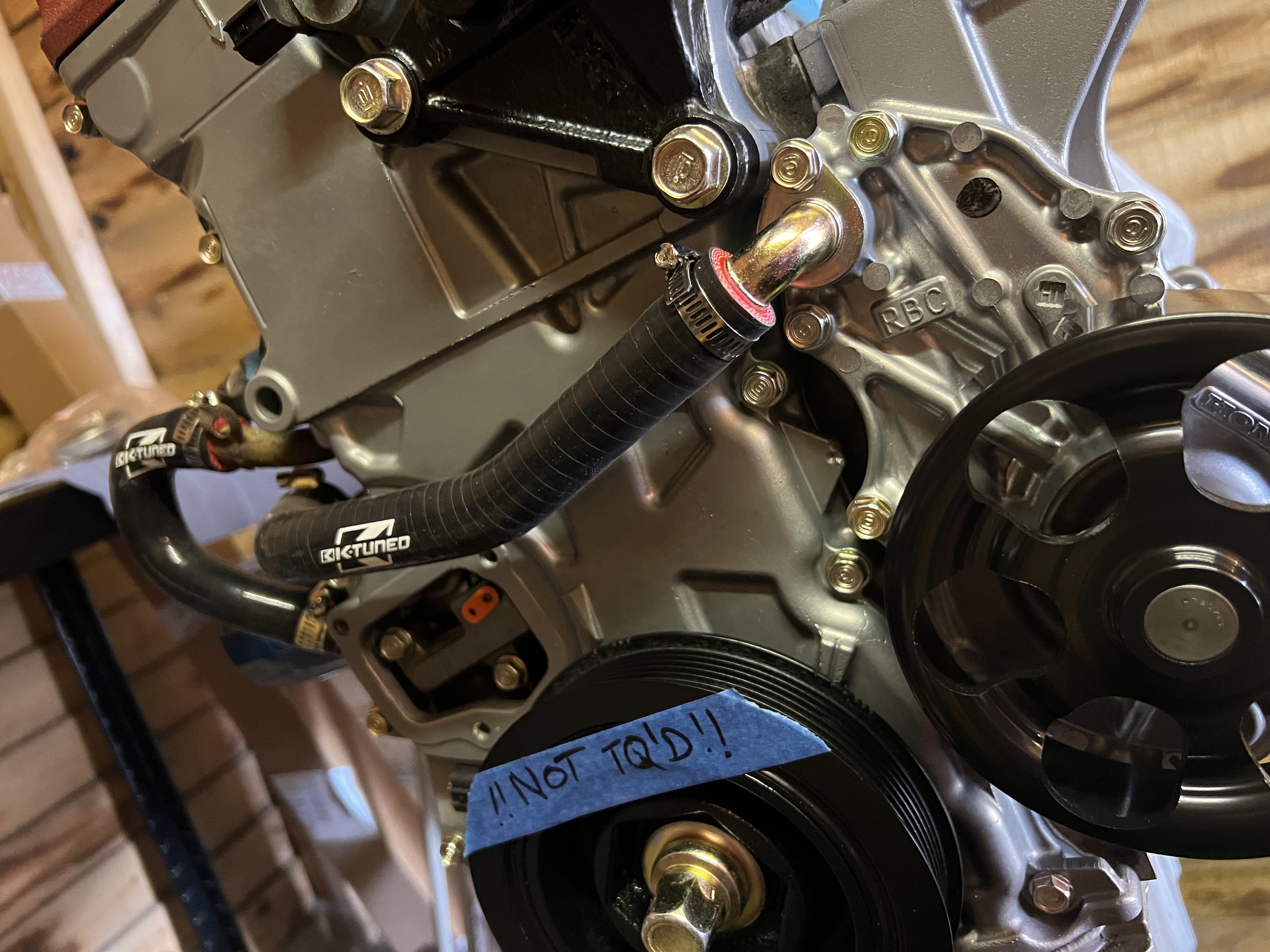
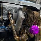
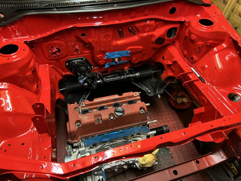
Cheers! Doing some of the plumbing at the moment. Few more bits to do on fuel lines and vac lines then that’s complete too.
-
Progress has been good, hopefully in a position to start it next month
-
Nice work going on here 👍
-
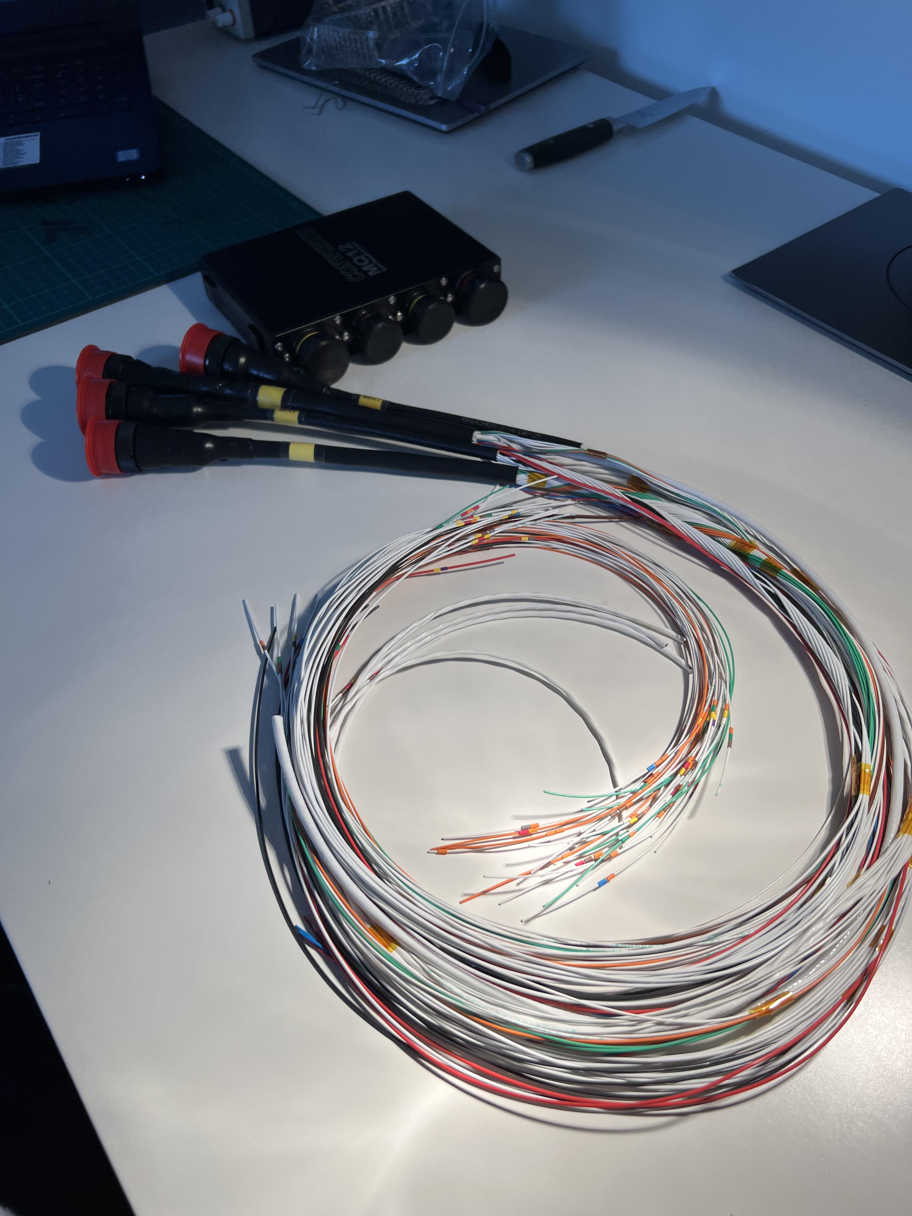
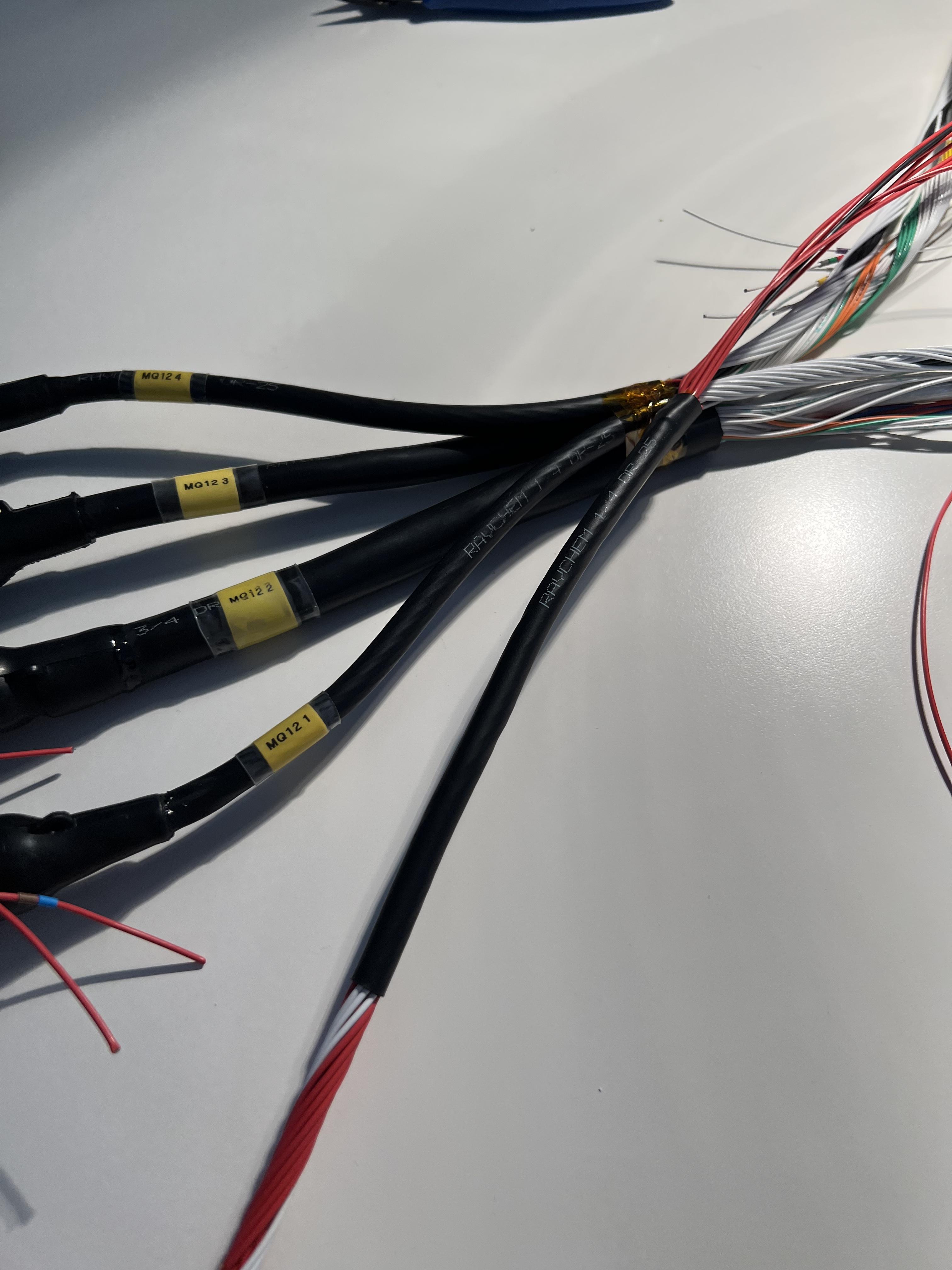
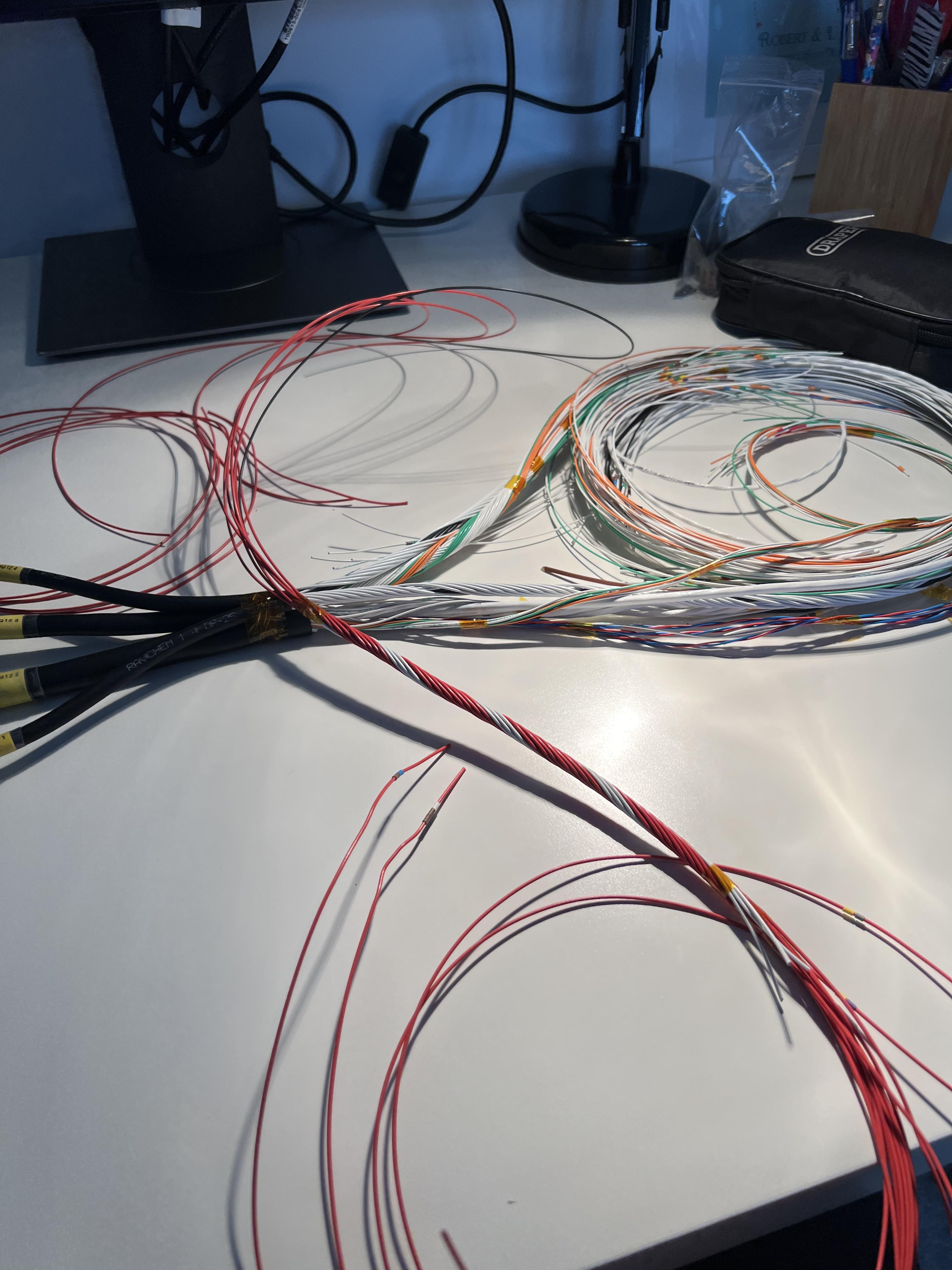
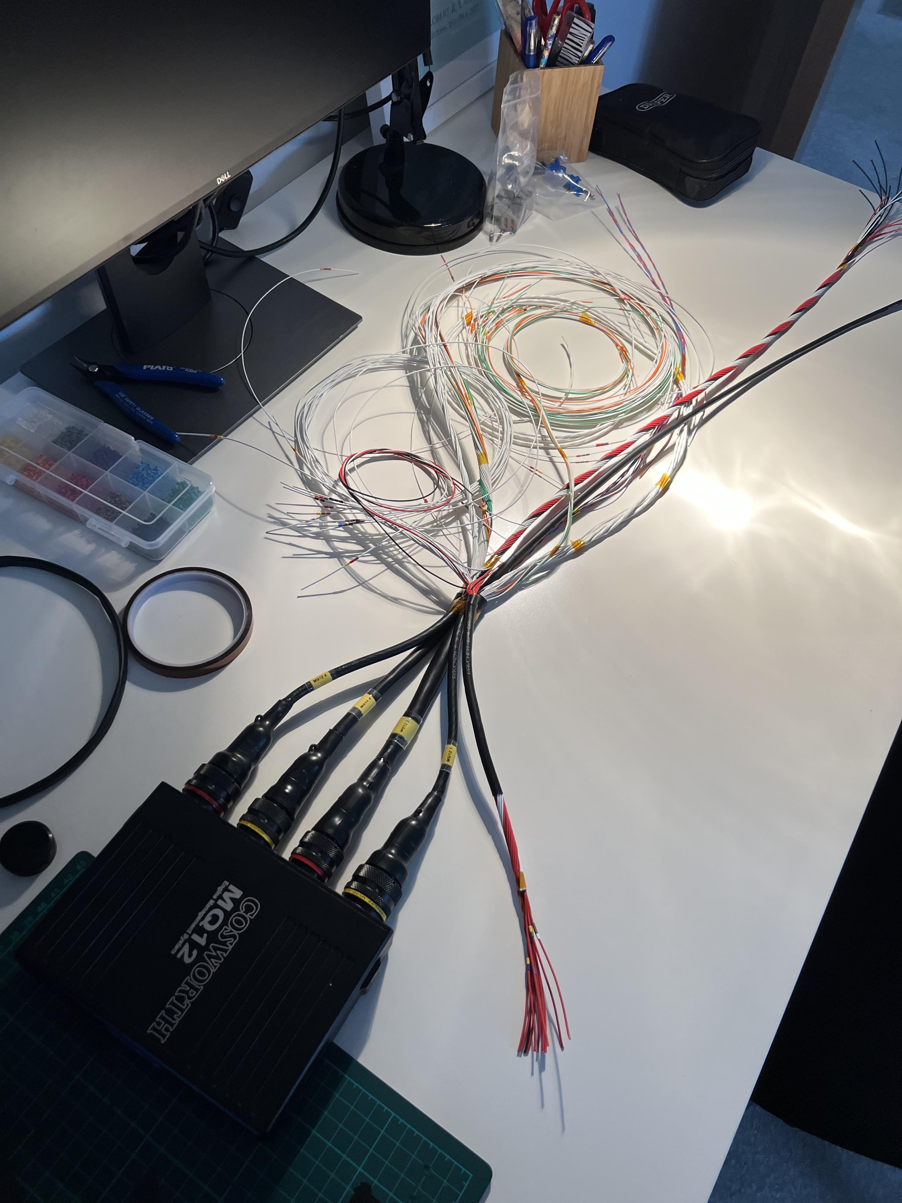
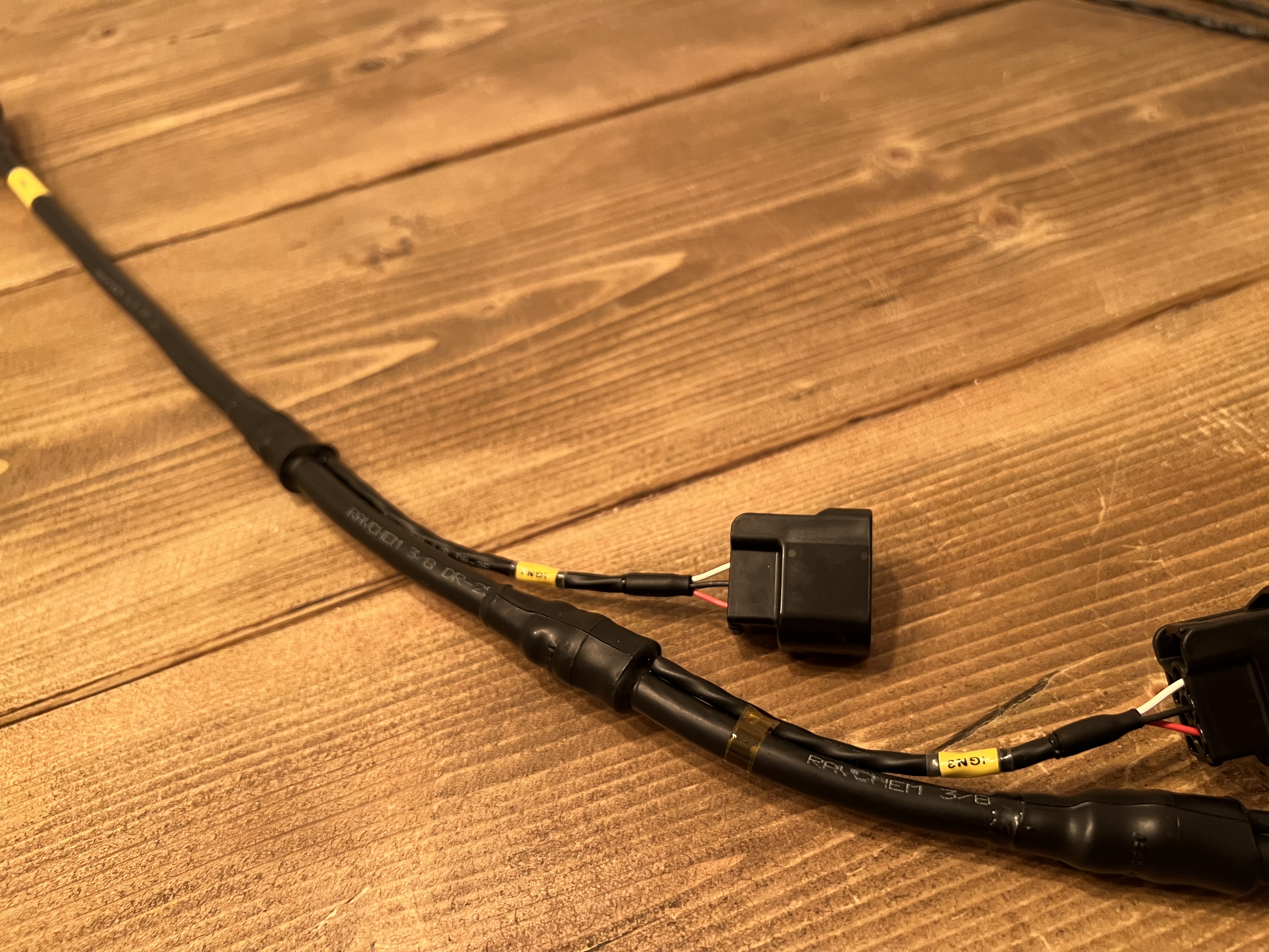
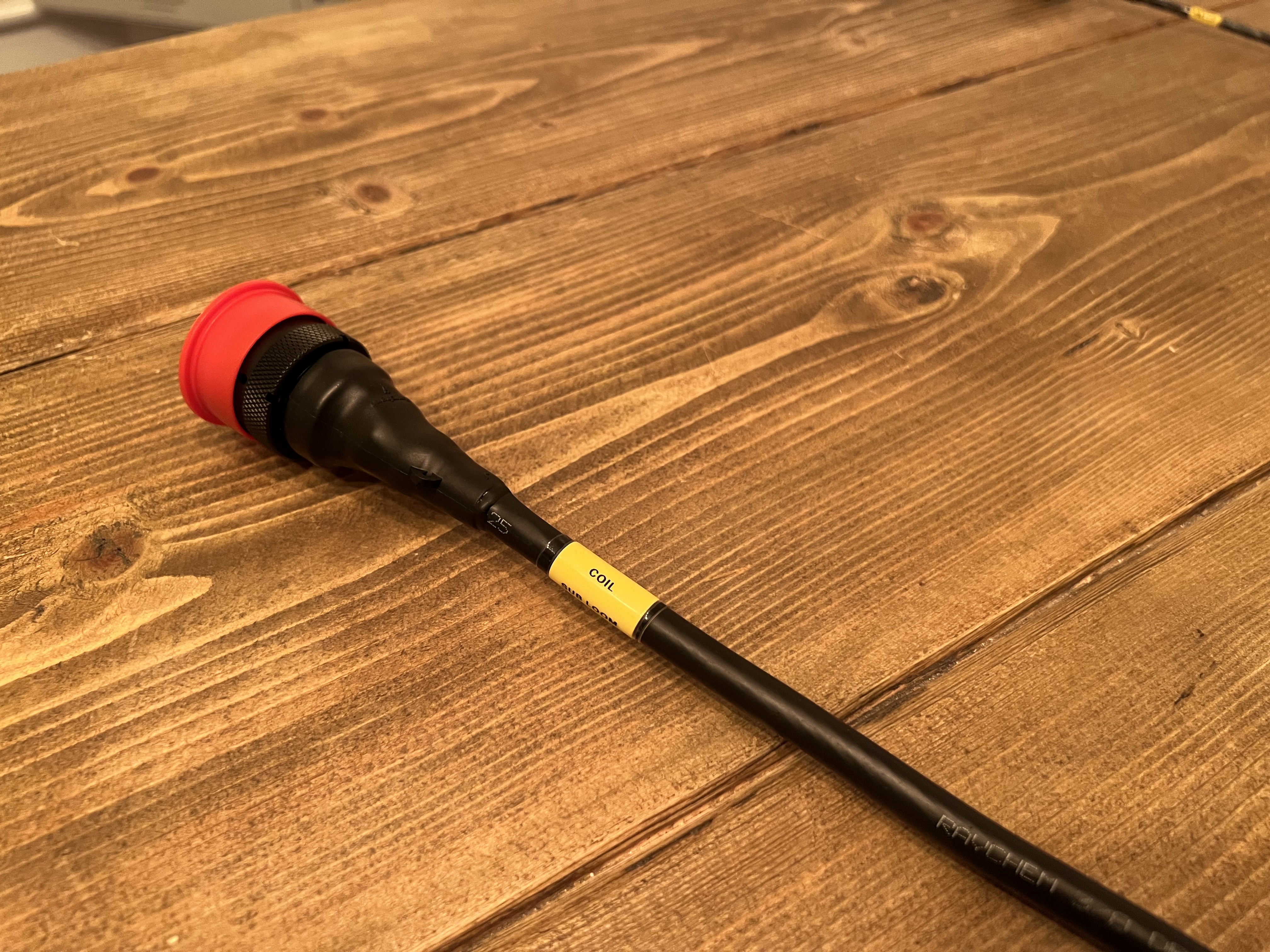
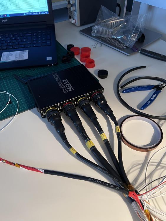
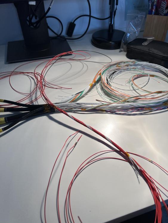
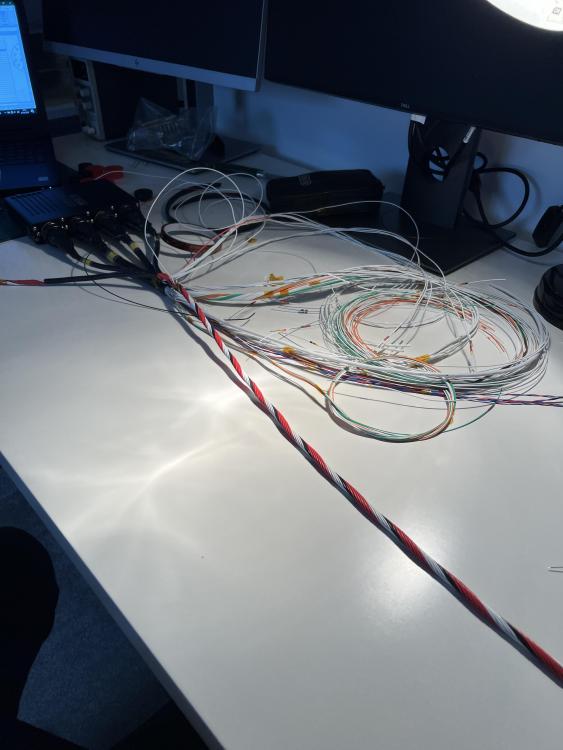
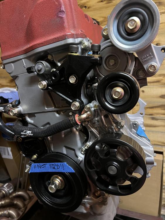
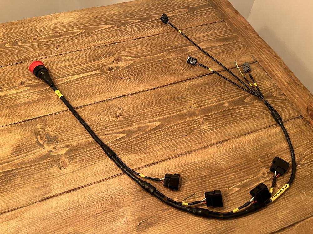
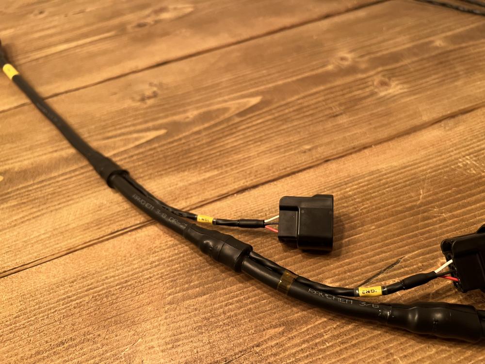
The next wiring headache underway


-


-
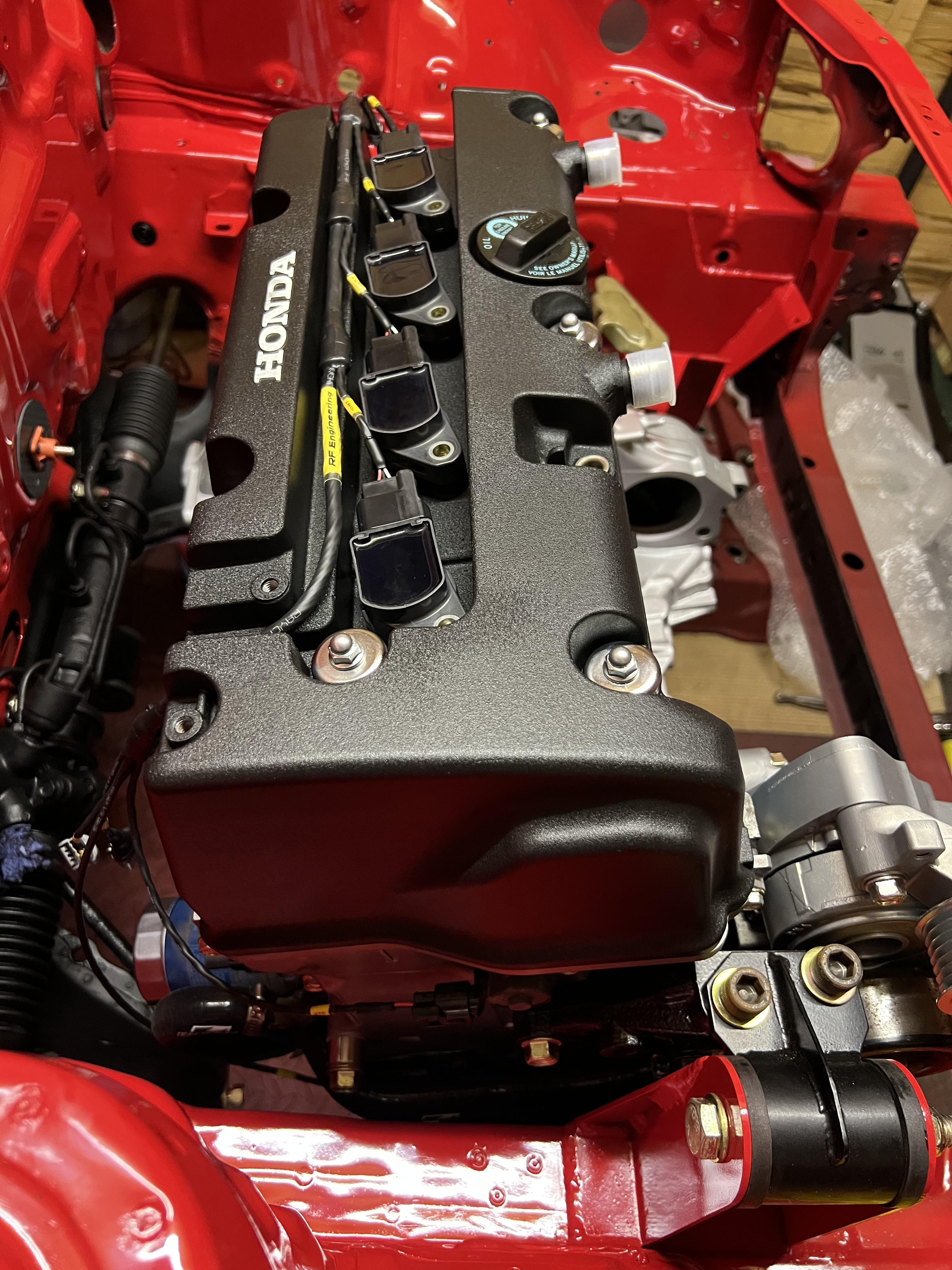
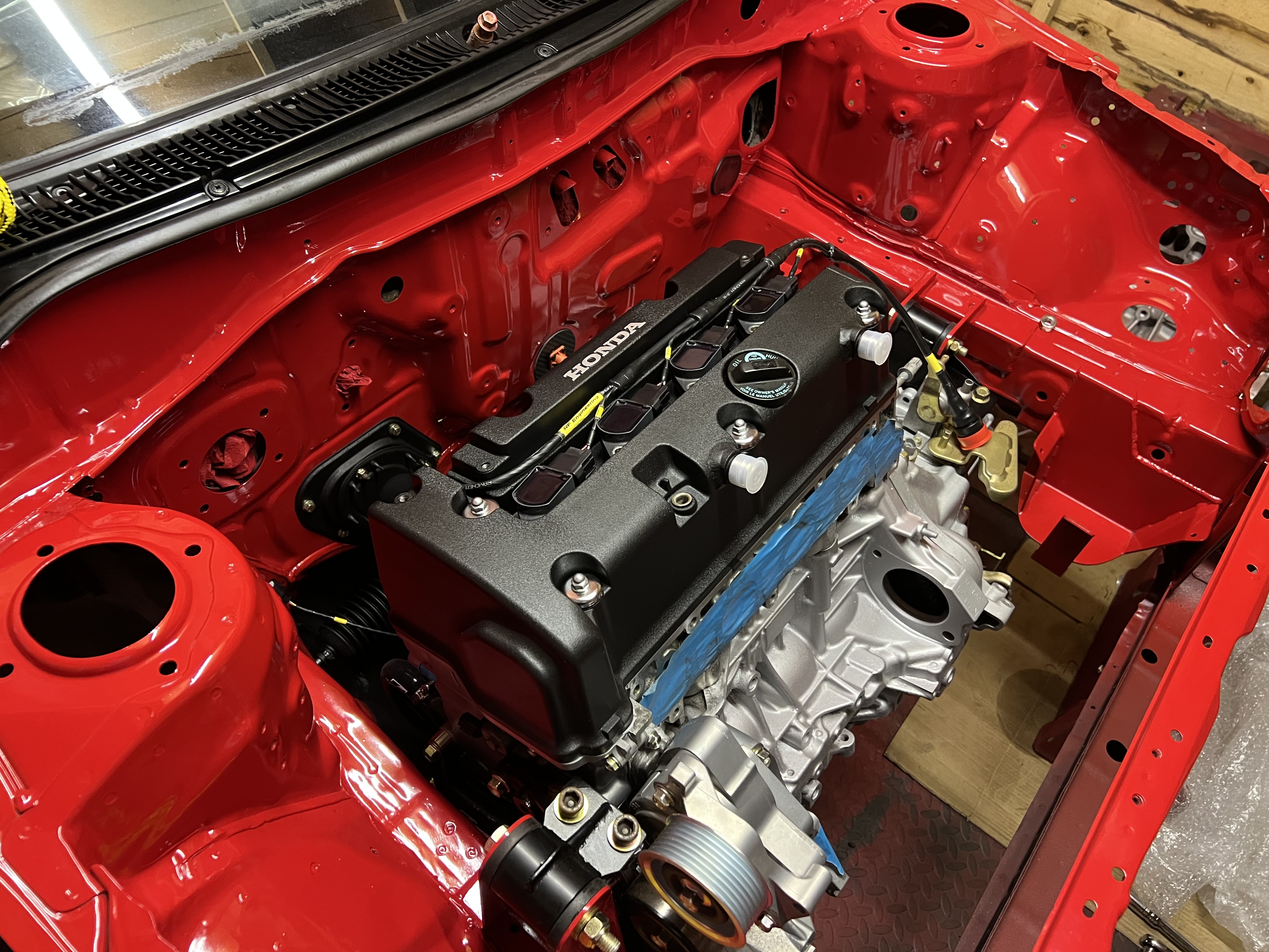
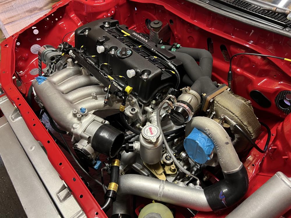
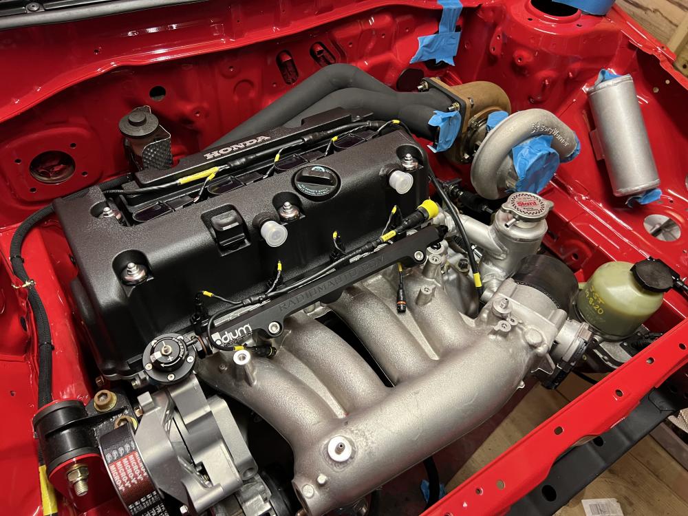
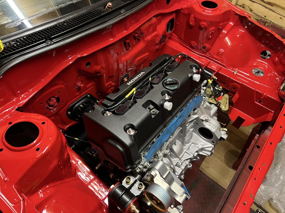
Thanks! It’s mounted back in for good now
-
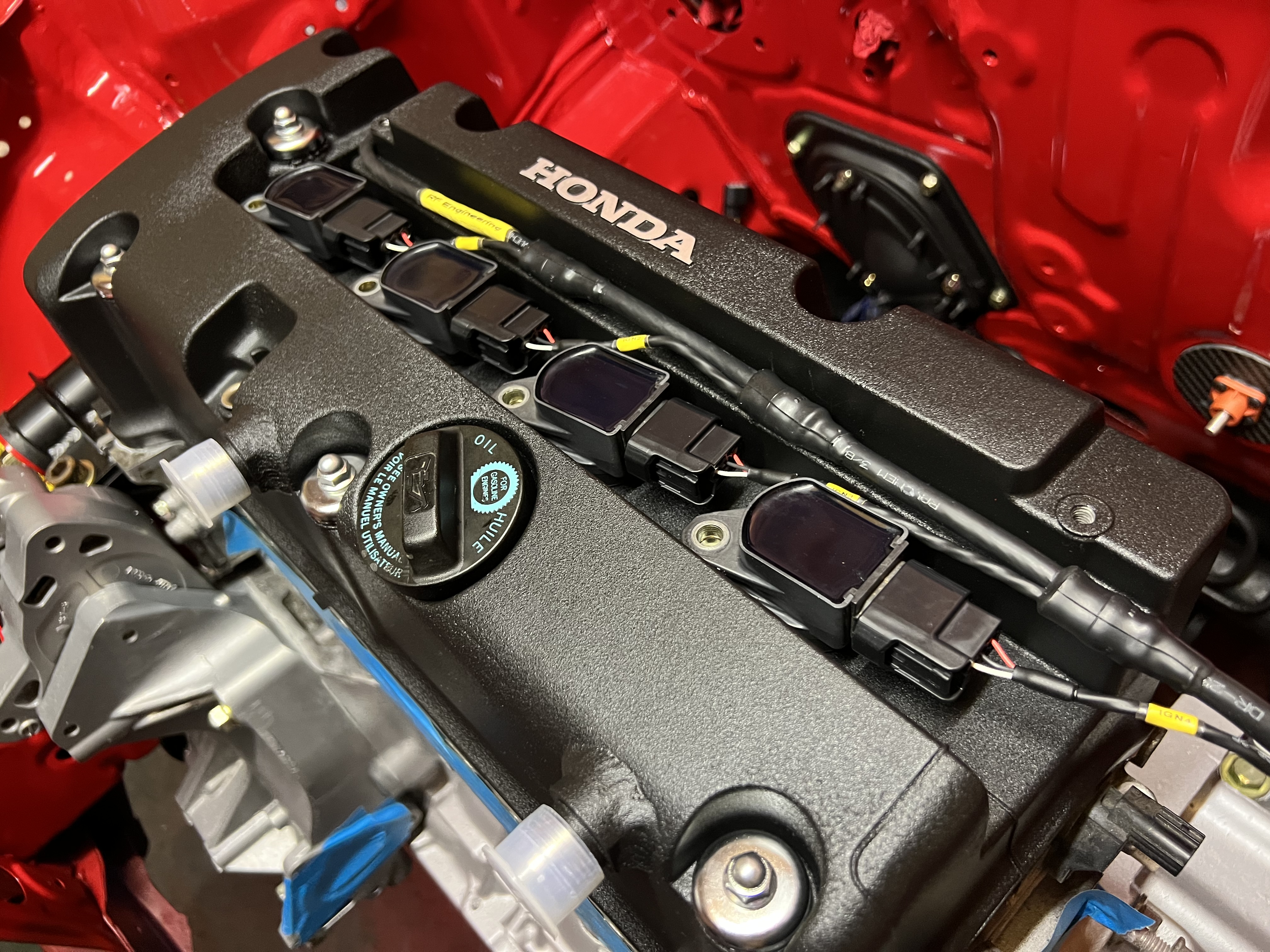
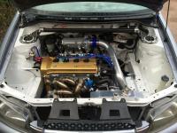
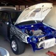
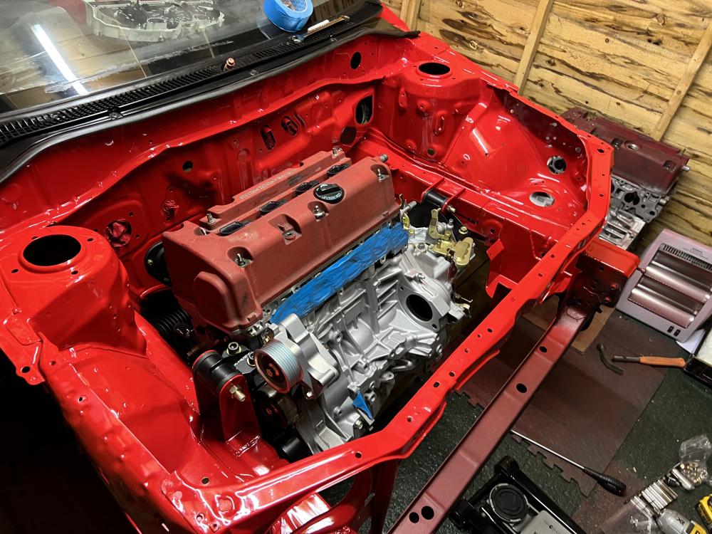
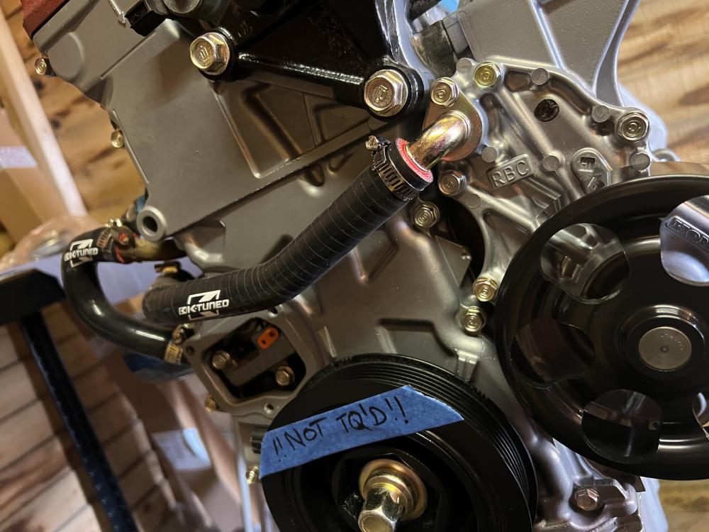
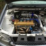
Ready to go back in for good now! All the engine work is done, got the majority of parts vapour blasted or painted and all the old bolts re-zinc plated too Refitting with temporary cam cover so I don’t accidentally smash the new one to bits lol
-
Have been trying to make some videos of the build too:
-
Thanks all!
-
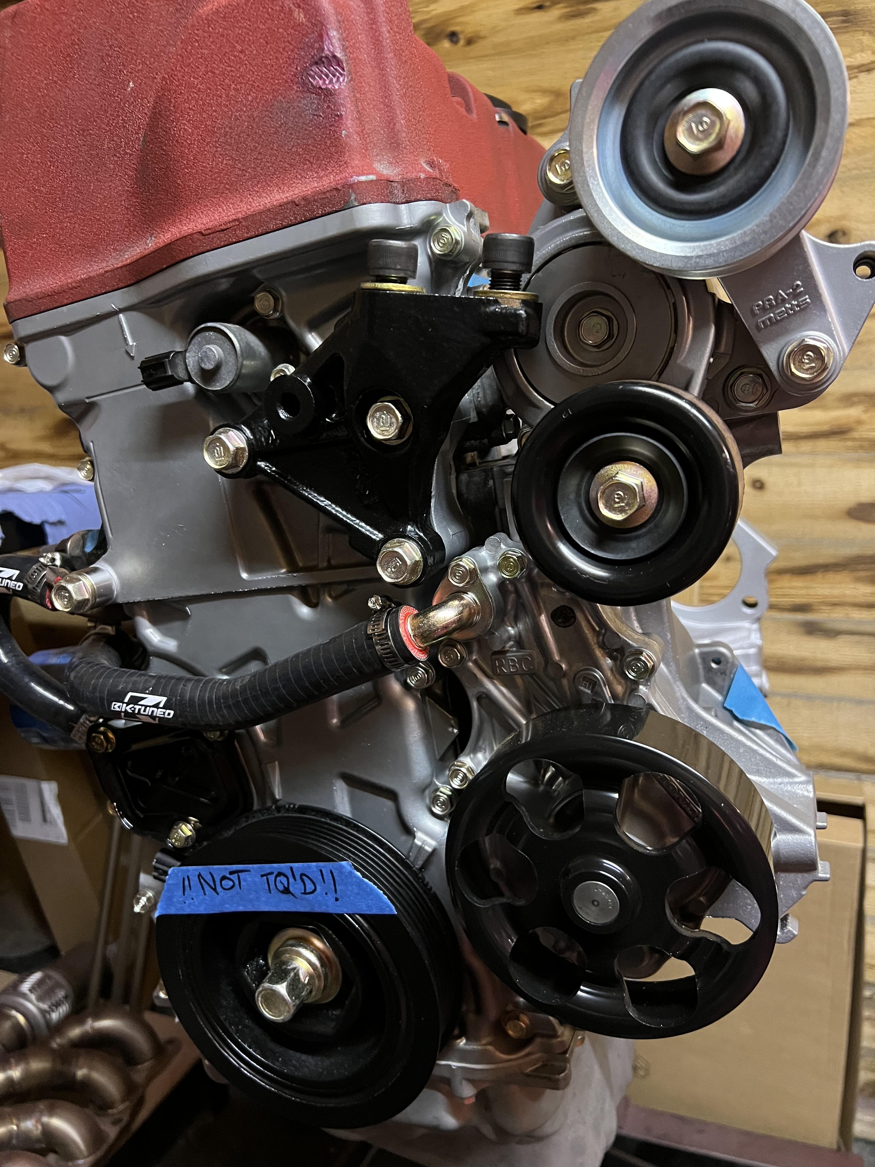
Mostly boring stuff! Loom work, engine bay painting, new oil pump and timing chain on engine etc etc. Moving onto the brake kit next.. have to do some more work on the shafts also

-
4efte throttle on Corolla E11 4efe inlet
RobSR replied to Frankieflowers's topic in Intake, Turbo & Exhaust
I would not bother. There is no evidence the ‘airflow’ is better, there is no plenum which a turbo engine likes and the runners are designed the way they are for an n/a engine to help with low end torque. -
Very few options for the autos. Probs easiest to get a Link or similar and fit it as a piggyback leaving the stock ecu to do the auto control