


Sam44
-
Content Count
1487 -
Joined
-
Last visited
Content Type
Profiles
Forums
Wiki
Media Demo
Store
Calendar
Posts posted by Sam44
-
-
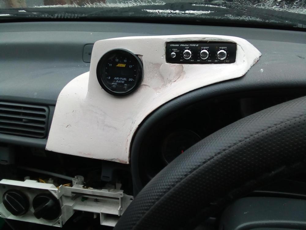
I'm working on a warning lamp system built up of led lights to warn me (the driver) of any faults or danger levels with the engine, gearbox and fuel system, which are not monitored by the Toyota ep91 factory system
Example: coolant level, coolant block pressure. Exhaust gas temp, det/nock alerts.
Please feel free to join in and give me things to add to the system.
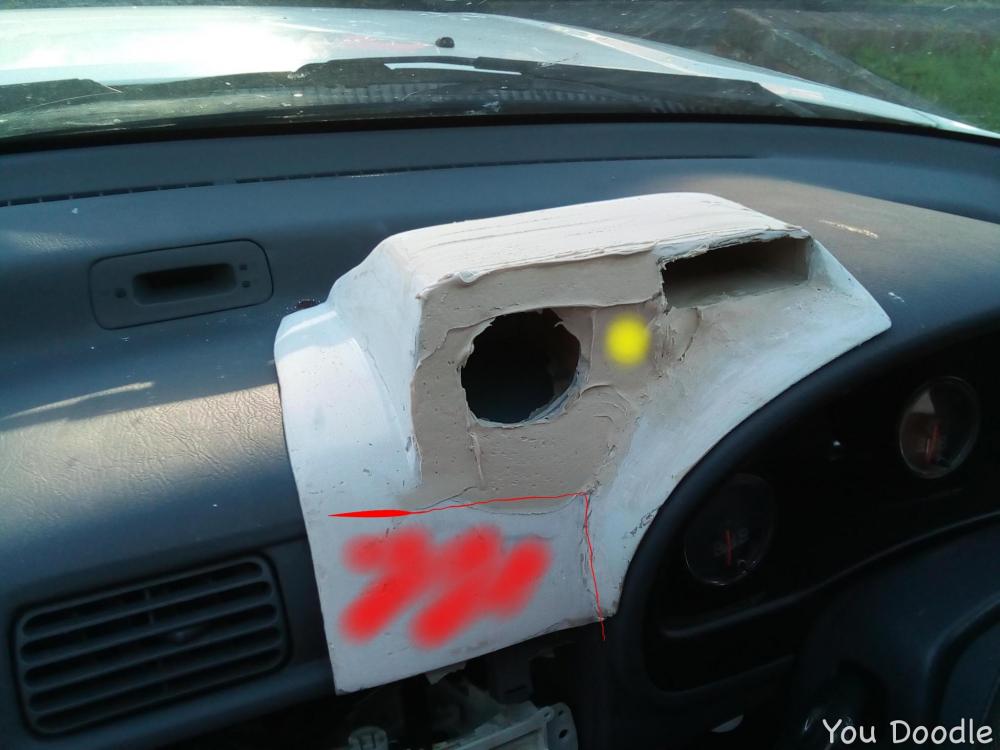
I've made this dash mount to house the led indicators marked in red and yellow.
-
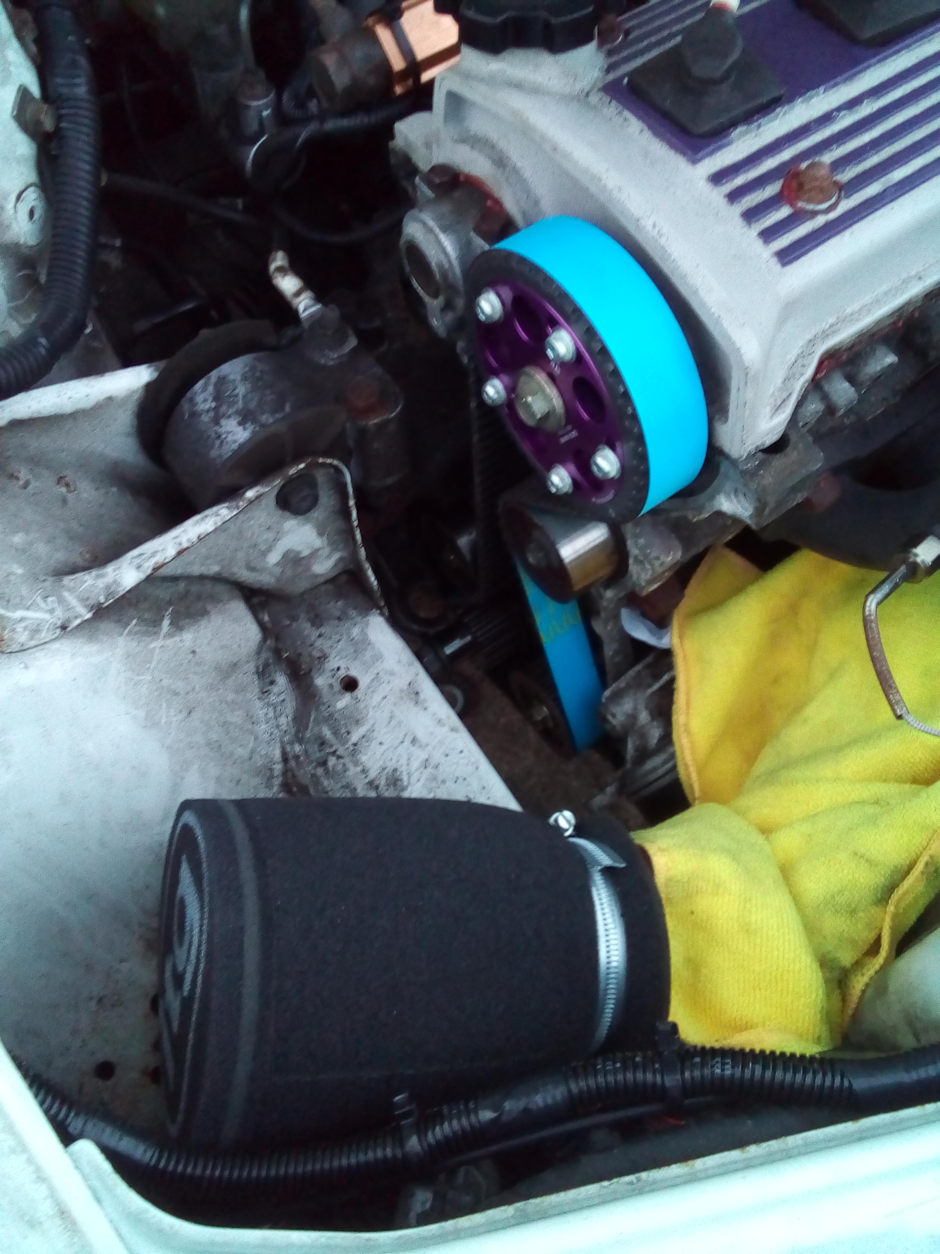
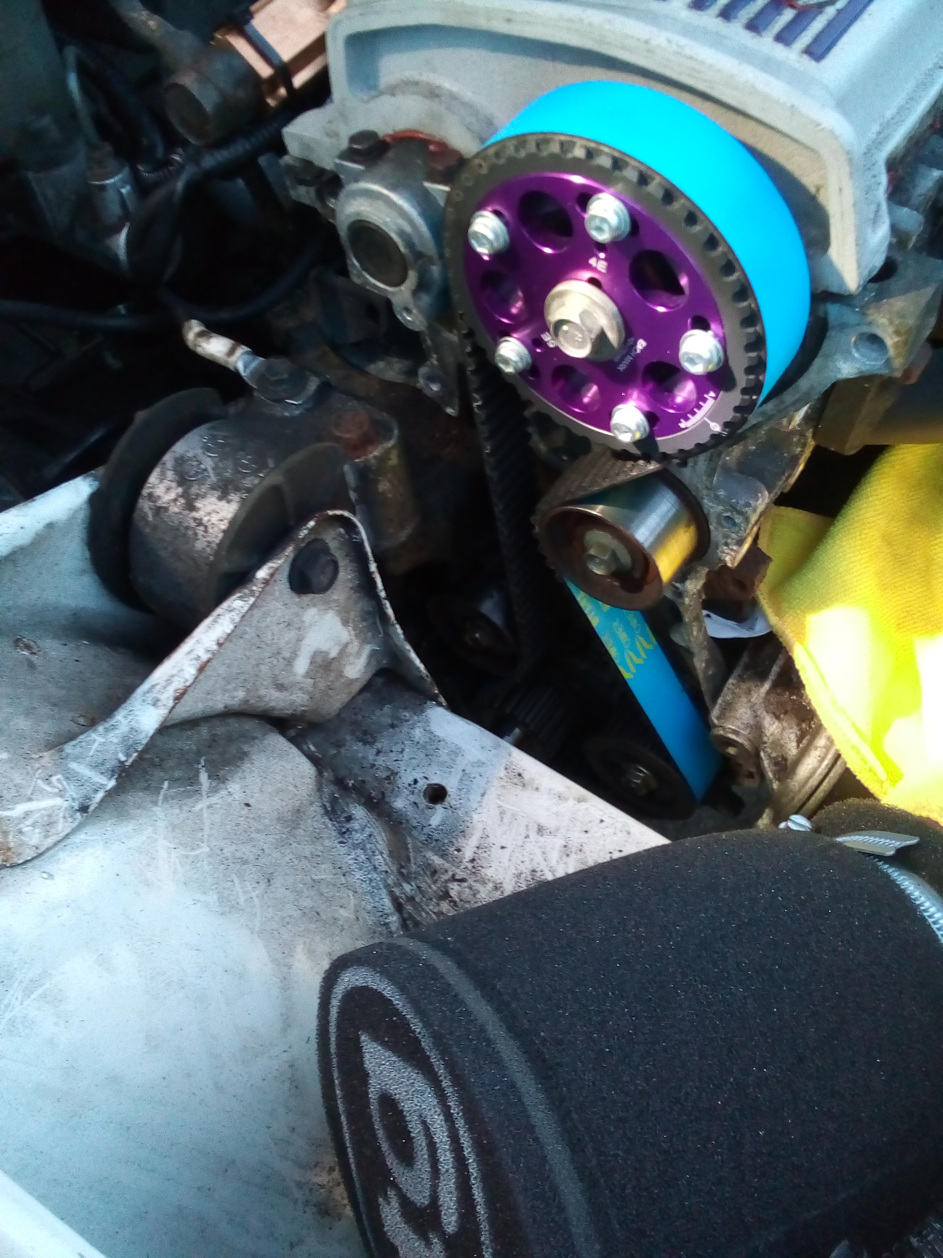
So a family member has done me a solid favour, and replaced the old cam belt with the new Kevlar race belt.
Process to do it.


I can't wait to be back.
I'm hoping this will minimise the flex of the belt helping the crank position sensor located in the 4efe distributor driven off the camshaft be more accurate.
-
Looking very neat with alot of care and attention in your build.
Turbo time. Keep up the great work.
-
Yeh same here silver.
-
Oh Waw fantastic work. Sounds so so nice. Well done lads what a transformation.
That lad knows his stuff + mods these cars crazy quick.
-
On 2/9/2021 at 8:01 PM, RobSR said:
I’ve clarified in the alternator topic for those that weren’t following.
Im not actually waiting for your data FYI, I have my own, I can post the X/Y plot now for coolant pressure on a high comp 4E for everyone to see; if you had it, you’d have posted it all the months ago when you were using your own “scare tactics” to other owners.
The thing that frustrates me is, I do post constructive points, with evidence and data to back up my claims.
Yourself however, do not; you post complete speculation that some unfortunate members will take as sound advice.
I find it even more frustrating where you’re still relatively new to the forum, and start moaning that people are posting “scare tactics” and not sharing their results, which is what the majority of your posts are; do what you like with your build, the way you want to, just don’t be a hypocrite.
How can I of posted it months ago the data is at my home in the UK, I'm in North America with work. As I've said many times. I'm so glad you have your own. Saves this conversation happening, figures crossed.
-
I've ordered 1 so we will find out. I'm confident it will be fine. I will swap the front pully over off the 70amp 4efe unit. Nothing to do the diameter more the fact of the length.
-
Looking smart as fook.
-
Yep it's good to be apart of a club were capable like minded people can discuss things. Gets right to the nitty gritty bits.
And yep I know I'm just pointing out what I came across and to point it out. As well as ask the questions that are on my mind about people's setups and Toyota systems threw the ages. Always a pleasure to discuss these with you. I try not to read or use emotion in my posts, as honestly what's the point the only person getting wound up is the person doing this.
Just on the ep91 UK 4efe system the fuel algorithm using the tps is very much suited for n/a application.
-
I've just seen this now I'll get some pictures up.
-
On 2/9/2021 at 7:03 PM, Claymore said:
The reason I comment when I see posts like this is because you present these ideas as a "silver bullet" to fix a tuning problem (intentionally or not).
In the above example, sometimes the important downsides / negative effects are overlooked / forgotten or missing for what ever reason. It fixes one problem but causes 3 more and you only mentioned 1 of these.
For the less experienced reader, they are not presented with a balanced view / whole picture and may make decisions they regret.
It's just a process I find my self going threw as problems present them self's to me, these normally match up with other questions I have like "why is the more modern ep91 4efte control unit the same as the early gen1 4efe"?. Also pointing out the difference of the EP,804efe video and ep91 UK 4efe you have put up seeming matching the 2x systems as the same. There not. Also it's much easier to map in the earlier type system on something like a det3 low table resolution.
I really do enjoy our conversations on here because my thoughts are verified most of the time, as well as giving me more to act on with new ideas. Thanks for the input, it's very constructive.
Were as Rob comes on and provides this kind of crap. In the above post. Which I'm really not interested in.
-
im not trying to do anything, only document what is possible.
this system is the same system for both the earlier ep80 gen 1 4efe and ep82/ep91 4efte have. why is this?.
this might also be interesting to lads seeking power from the N/A 4efe. or having immobilizer issues.
i have recently gone back to the uk ep91 4efe ecu after intercepting the tps signal after i was not happy with the amount of fuel i was having to add.
the earlier ecu is easier to map in if your a novice having a go with a simple piggyback like the det3. it also matches up to the ep80 setup in the 4efe+t common video on you tube.
as covered in other topics you can set up inlet systems and cams in many configurations to achieve your desired torque curve. the biggest way to alter the complete power graph.
you can get the 35mm ae101 gen1 throttle and the 4efte 45mm i think might be bigger both do very different things with the 4efte power manifold both fit. also on this subject the 4efte throttles do not fit the corolla tubular manifold, 5e, 4e manifolds they bolt on but overhand slightly needing a backing plate making the same happens with the ep91 uk 4efe if used on a 4efte power manifold.
i will edit the post above with how to setup the throttle body removing the 4efte and gen 1 4efe idle control valve. it has been covered recently on here also.
the subject is turboing a 4efe engine. any and all welcome to join in and all information welcome. you can also message me if you like.
-
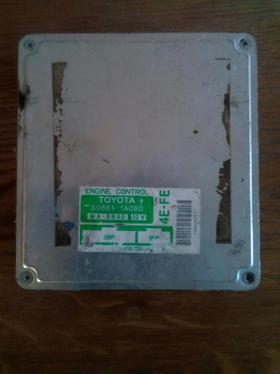
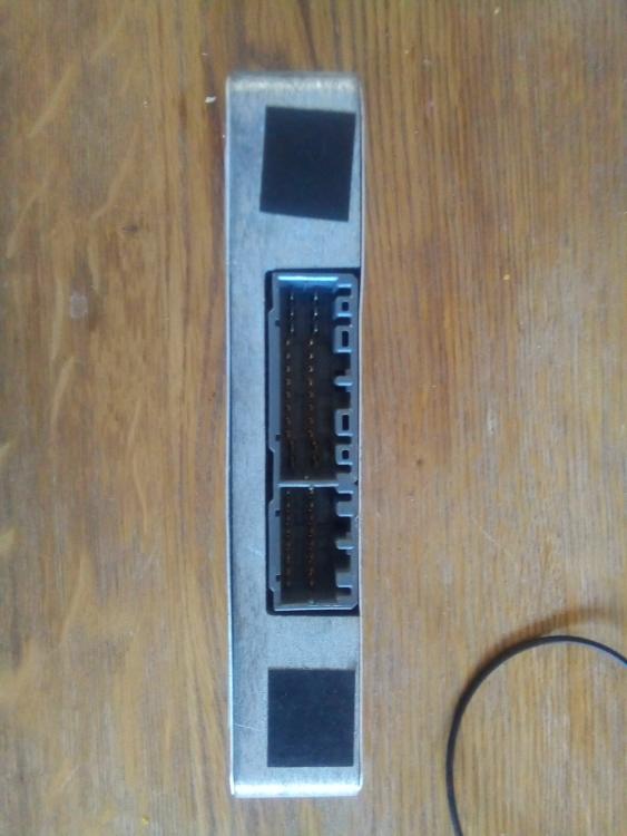
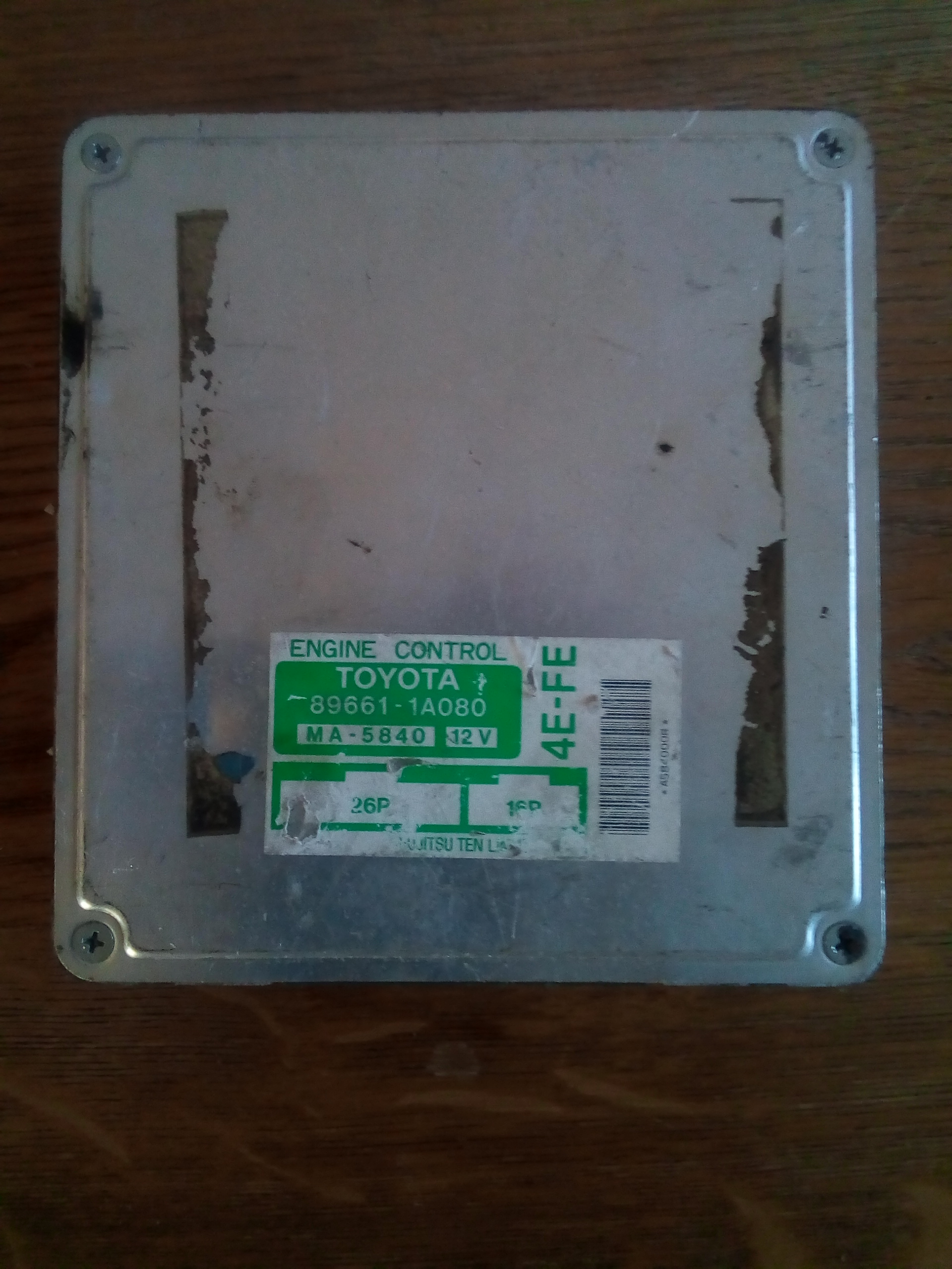
 Gen 1 4efe 88hp ae101 ecu.
Easier to work on the piggy back. Works with the bigger 4efte throttle body/position sensor (3way switch type).
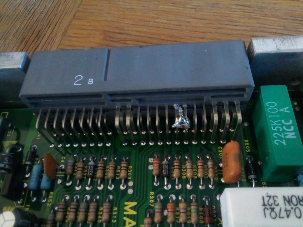
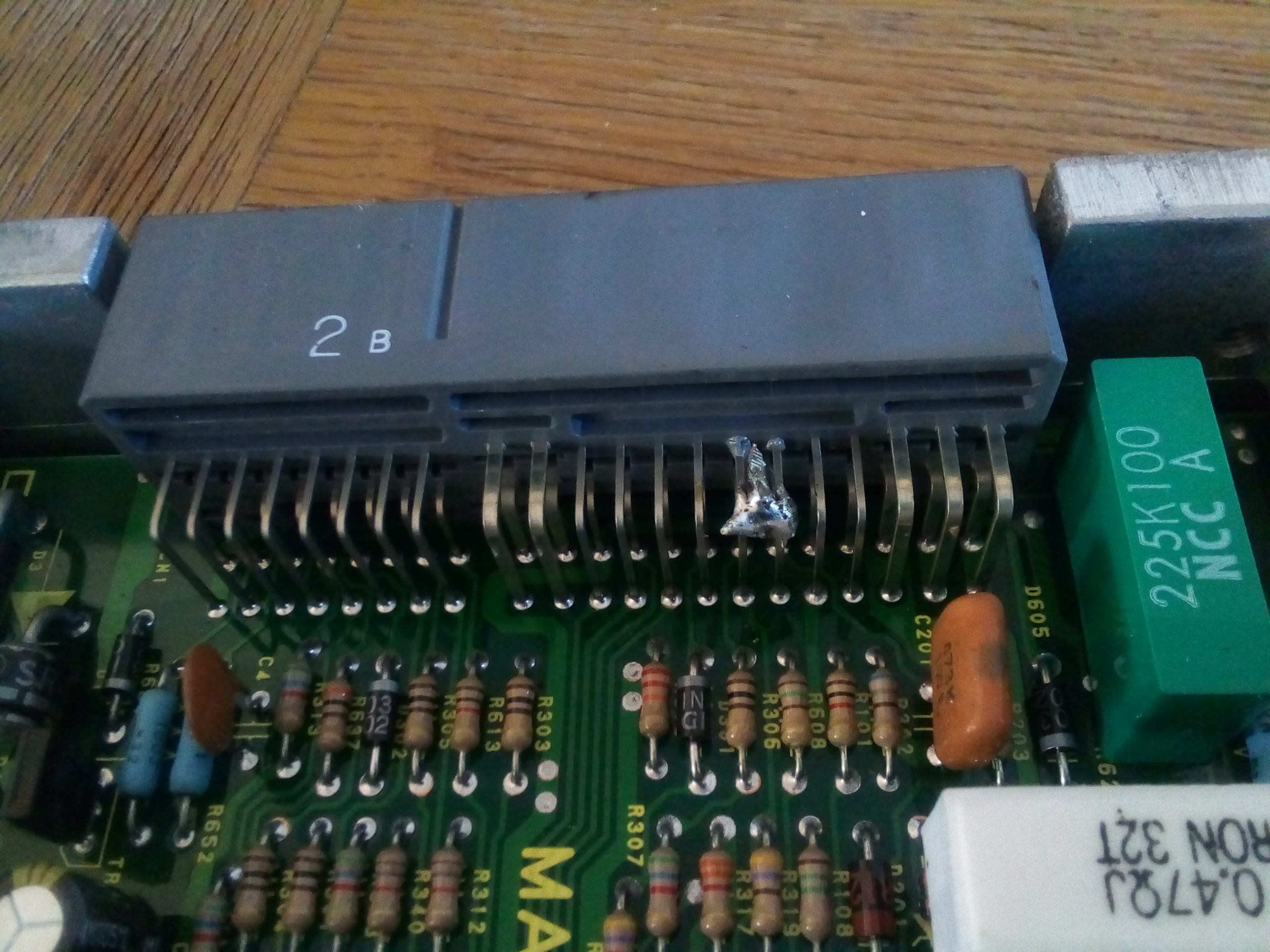
The starlet ep91 plugs are the same and this also has no immobiliser. All that is needed is this mod on the internal pins.
I was hunting these pictures all last night to get up.
This ecu fueling algorithm is the same as the 4efte in both the ep82 & ep91?. Just different values in the equation (boost). The exception is the auto ecu on all models (advanced,great but of kit)
Slightly different pin configuration, soldering these 2 pins together brings it to life on the UK ep91 platform. the only other difference is the idle valve what i did was to leave the ep91 idle valve plug off and setup the idle using the idle screw located on the top of the 4efte throttle body.
The difference between the ae101 and ep91 4efe is reported to be around 10 to 15hp, but i suspect around 20ftlbs more torque output from the ae101 setup, (going off the lads that have run the 4efte power manifold and ae101 exhaust manifold on the ep91 4efe).
I've learnt so far is the tps,inlet manifold (power 4efte) injectors 210cc light brown denso, exhaust manifold 4 to 2 to 1 short style (affecting mid rpm range torque)
The 4efe gen 1 original throttle size is around 35mm.


The ep82 has the same ecu plugs but a different dizzy setup it will not work on the UK ep91 unless a small adaptor loom is made from the ECU to the dizzy and ignition amp. Consists of around 5 to 6 wires.
How to setup either the 35mm ae101 throttle body or 4efte throttle body. You can also keep the waxstat idle up valve on the underside this helps with cold start idle up and also helps mpg by reducing air density, this does how ever reduce engine torque.
-
Rob I really don't mind you waiting.
Why don't you tell us how alternators work.
I was hoping for something constructive when I saw your name. Maybe next time.
-
she will be a 70 plate before long keep up the great work.
-
nice picture and motor, as well as abit of history.
-
no technical exercise. these questions come about as i start to look at some of the components on the 4e and its relationship with the system in general also some of the more common fitted components and the affect they are having on the system.
if there is any 1 that wants to put up any info running the 4efe on the fcd/injector/fpr approach please feel free.
another is people not using the air temp sensor?. are thy unplugging it driving the ecu into a fail safe mode or just hanging it in the bay to read engine bay temps?
how much of an affect does this sensor have on fueling overall?.
you certainly have helped me clarify my thoughts on the adjustable type FCD. i just need to verify this with my scope.
ive been looking into the hks FCON control units recently. a seemingly smart control unit and quite user friendly, as well as being able to work on the original map sensor.
mpg helps analyse the overall tune both around town and motorway usage. both against the engine/turbo setup and map.
and like you said its mainly cost against proven power and safty. i would just like to throw efficiency in the mix to help people understand a good tune (overall setup) for speed and power balance.
a good thing here is if you have run a 4efe before it was turboed and how does it compare now.
-
no i was just wondering how mine was on a 1bar original map sensor, purely just going off the fact it had a blue label. as ive explained in the previous posts its been checked and found to be running a 2bar sensor off common lexus and toyotas.
this is the direction of where my research is going with the 1bar map sensor and hks adjustable fcd. with me not able to test the system at present for peak voltage (fuel cut) as well as voltage raise against pressure both negative and positive, and the affects of the hks fcd on the voltage signal.
i cant find much online, there is the normal forum guess work and scare tactics, but no hard evidence, and the lads doing this work simply go under ground. they do not post there results which is a real shame.
as ive tried to hone in on the fueling algorithm used (example in a previous post above) it becomes apparent that the fueling is doable using the larger injectors and adjustable fcd method. the map sensor will quickly drive the fueling rich upon boost, the throttle will apply more fueling as it opens at this point the fueling isnt fixed. the question here is does the map have an IDLE & WOT point on the TPS. answer is yes it does so if we make this adjustable we will loose either base idle or WOT. also can we affect/reduce the base map sensor voltage using the fcd if so happy days (bigger injectors are fitted). also we can now fit and use an adjustable raising rate fuel reg designed for this exact cocktail.
ive spoken with a few lads on here that have run this setup for years with no issue.
unfortunately they are quickly ridiculed and feel unwelcome on the forums.
people will now mention exact fueling, do we honestly think exact fueling is something we can achieve using simple piggyback.
-
the 4efte inlet will help delay the spool up of the ct9a turbo your running also. so this should help mpg slightly.
mine has not got an fcd in the system. just the stated map sensor.
i was wondering on the voltage that induces fuel cut?.
also why is the hks fcd adjustable does this bleed off voltage or clamp it?. if so would it be usable on the 4efe 1bar sensor.
all these questions are out there.
-
no mine has a more modern blue labled 2bar denso map sensor from a hylux on it.
i know the civic denso sensor didnt hit 5v at any point it maxed out around 4.2v at 6psi/8psi if i remember correct (thats the voltage from the map sensor into the det3) we think this is the original sensor for the d16y8 engine but he did get the car in bits with alot of the turbo parts already purchased ready to just install, it was a ongoing turbo build.
i just adjusted the tables for best response on the det3 making the most and smoothest power i could.
but yeh your right if the sensor tops out at max voltage then its no good for a piggy back referencing load.
i have been wondering at what voltage fuel cut comes about.
i might have to use the det3 in fuel implant mode, which does not look to hard to be honest, and looks to be a much better way to use these.
i have been having a good read up on there web site.
one thing that became apparent on both my starlet and the civic was the presence of an alfa N style algorithm linked to the TPS. this became problematic with the low table resolution of the det3 in piggy back mode, and the aem when using a cat and oem lamba to preserve the life spam of the high flow cat.
i did swap the ep91 4efe ecu, with the ae101 4efe gen1 ecu (almost plug and play) with the 4efte throttle & tps & i might add does not have a coded key mobilizer luckily, also the same ecu design as the ep80 in the video, that uses a true speed density map with the tps only affecting idle and wot conditions. a much easier ecu to get the fueling right.
ive since sorted this and im back on the faster processing speed of the ep91 4efe ecu.
the old saying was used alot on the civic FUELING FOR SAFTY!!!! which i personally hate. (basically over fueling) hes going to monitor his oil grade/contaminents, and egt over the next 12month
im also very interested in your mpg once finished?
are you going to run a cat?.
-
yeh i get you. if the det3 map sensor does not determine load like the aem sensor does.
-
im going to get another simple tdo4l 4efe done for a friend as soon as i can this year on the det3. so all this will come in very handy.
im also going to try and setup the output of the original map sensor to accept boost pressure like i did on the turboed civic d16y8.
-
great info let us know how it goes.
have you got a timing gun.
-
let us know how you get on it will help others. also which is the closest configure reference if possible.
ive just had a look threw the setup tables and edited my first post with more information.


Dash light warning indicators.
in Electronics
Posted · Edited by Sam44
im designing a cmos logic IC, there not really that pricey.
its there to help me fault find, as well as give me instant warning to which system is faulty. i can also make them sensitive/progressive.
i can also put things in the car in there like boot or doors open.
i suppose the real danger zones i can put on a buzzer to, thanks thats a good idea. ive got room for about 20 square red led lights.
there are afew items that are pricey, like the nock/det alert systems.