

Claymore
-
Content Count
660 -
Joined
-
Last visited
Content Type
Profiles
Forums
Wiki
Media Demo
Store
Calendar
Posts posted by Claymore
-
-
7 hours ago, richardc9052 said:
Are you building an EP80 or EP90? if its an EP90... I have the perfect size intercooler for keeping it hidden, but also maximising the space.
Size: 450X300X76mm

Thanks for the info, looks a good fit.
It's for an EP91 (build thread link's in my bio)
Might I ask, is that a TD05? 16g?, 18g?, 20g?
-
Also found this:
http://www.volkspage.net/technik/04/maximum_boost.pdf
Its a pdf copy of Corky Bell's maximum boost book.
Its a bit out of date now (the engine management section will almost be out of date at the time of print really.) and I'm certainly not recommending it as the only source of reading info on the subject, but it has some good insights and solid lessons to help understand the subject matter. The section on intercoolers is also where all the "trouble" started when comparing to other books on the matter. Still worth a read.
If you're interested, the Jeff Hartman Turbocharging performance handbook is a modern version of the above.

-
Whilst I was looking at intercooler setups I spannered across this on youtube.
Definitely NOT the way to mount an intercooler!

Fast forward to 8:45. Thought it might give someone a giggle.
-
49 minutes ago, Pikey009 said:
My rocker arrived today from RW-D. I’ve got to say, the quality is spot on. Not cheap but you definitely get what you pay for.
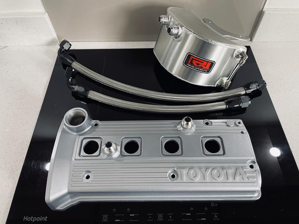

Top quality there mate. Nice to see a company producing to that level. Beautiful! 😍
-
Currently test fitting some 4efte injectors to an N/A rail using the N/A fuel rail posts. Its for my 4efe + turbo build.
The EP91 4efe injectors use the same rubber spacers and lower rubber seals as the EP91 4efte. The injectors are the same length and the only part number differences are for the rail and the rail posts (mid -96 on).
When I removed the fe injectors the lower seals were knackered so I replaced them with the used 4efte lower seals and when fitted to the head it is apparent that there was a gap between the rubber spacer and fuel rail and the injector could be pulled up out of the head!
So assuming the lower seals I got with the fte injectors are infact the correct items (you never know second hand) it looks like the 4efte fuel rail presses the injectors approx. 2mm further into the head than the 4efe. It may be achieved with shorter fuel rail posts or differences in the rail geometry or a combo of both.
I have since fitted new (aftermarket) injector spacers and lower seals to fte injectors in positions 1 and 4 (either end of the rail) to see the difference and there is only about 0.5mm of squash on the new seals when the rail is tightened.
Before tightening, rested on new lower seals and spacers:

Personally I don't think this is enough when you add 7psi of boost and fuel mix to the other side!
Worried about the lower seals lifting / leaking, also there is 2.X bar of fuel pressure trying to push the injectors out of the rail into the lower seals (momentarily between pulses).
So I could try new Toyota seals and spacers to see if the new aftermarket ones are wrong or possibly add a washer to the top spacer to add the extra 1mm of compression I feel they need. Or hunt down a glanza fuel rail and posts.
I know that everyone doing a 4efe + t build uses these injectors in the fe rail but surely I can't be the only one with this issue!
Or am I concerned over nothing?
Any input / experience greatly received.
-
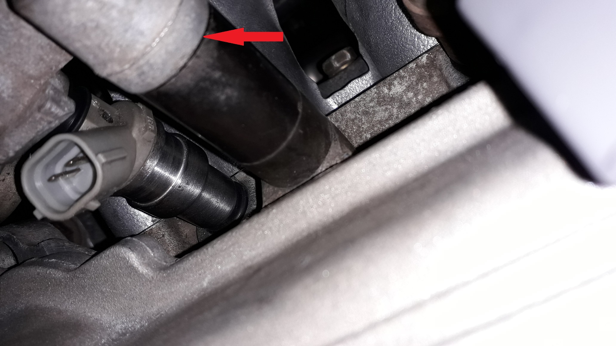
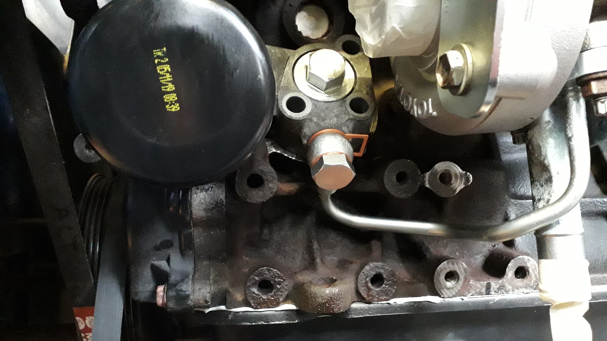
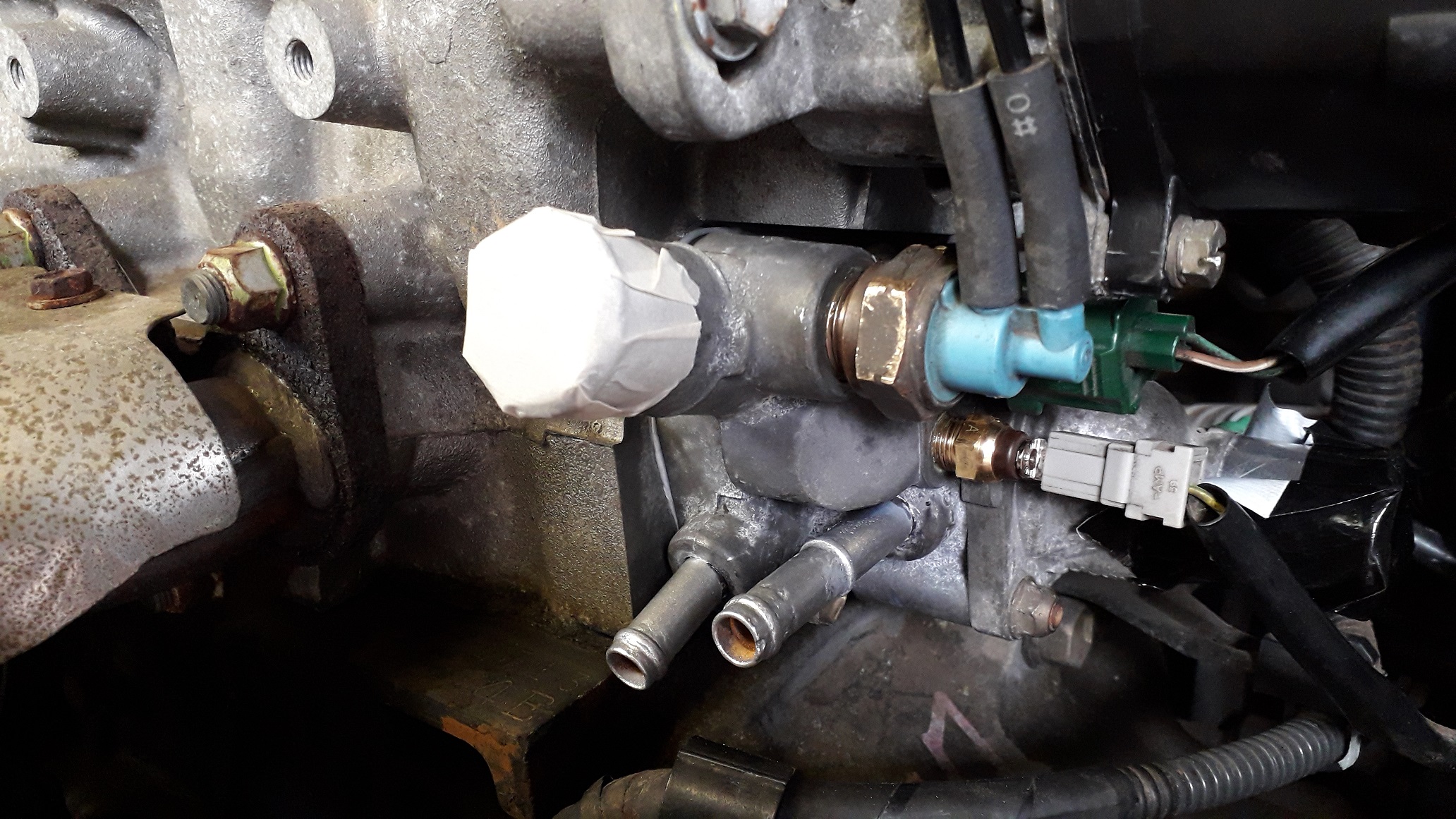
4efte oil filter relocator fitment.
Needed a way of getting oil to the turbo so the Toyota solution seemed the best and at least we know it fits! Bought a nice example off socks about a year ago now I think, was one of the first parts I bought when I had barely owned the car a month.
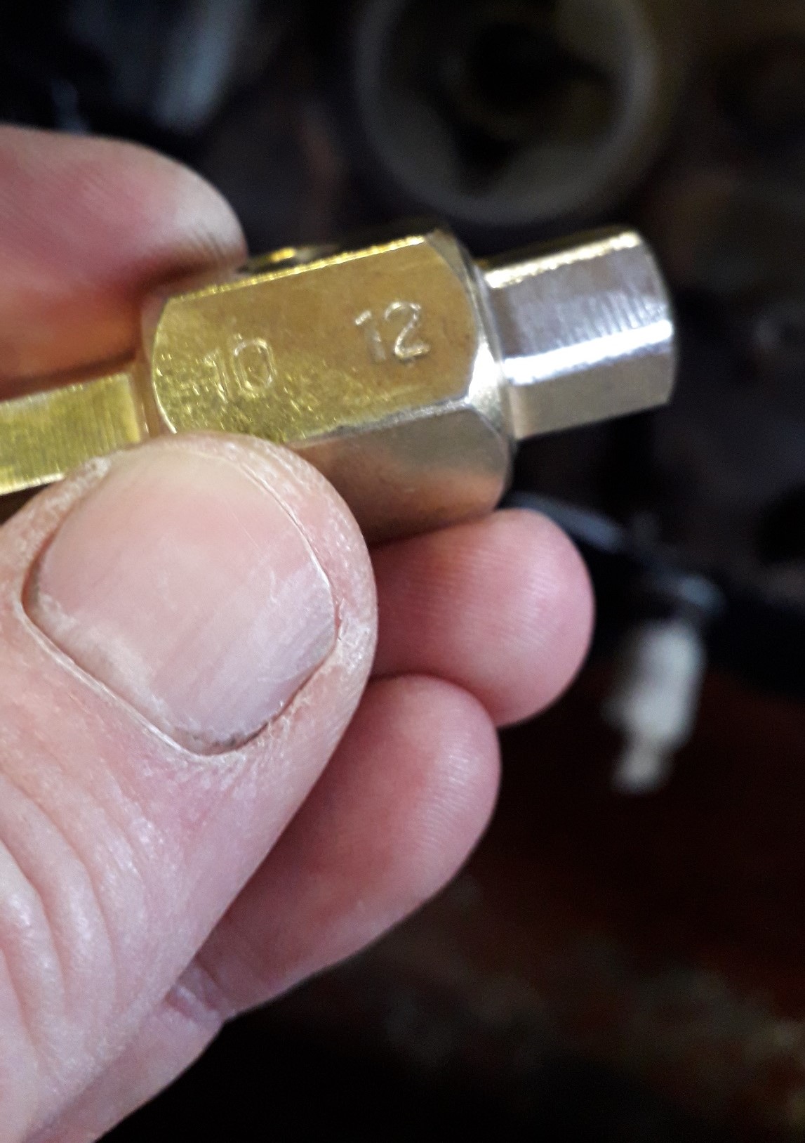
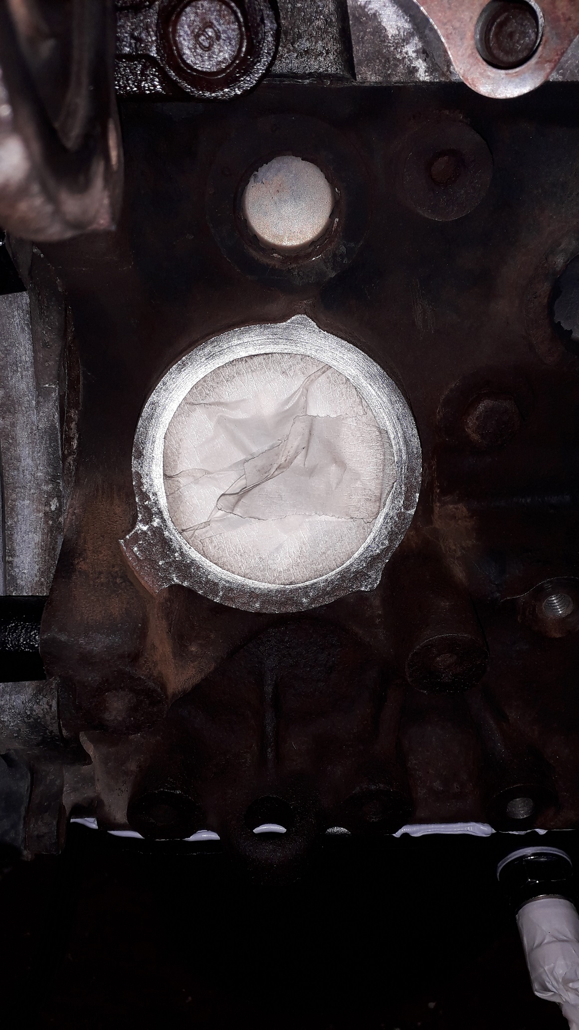
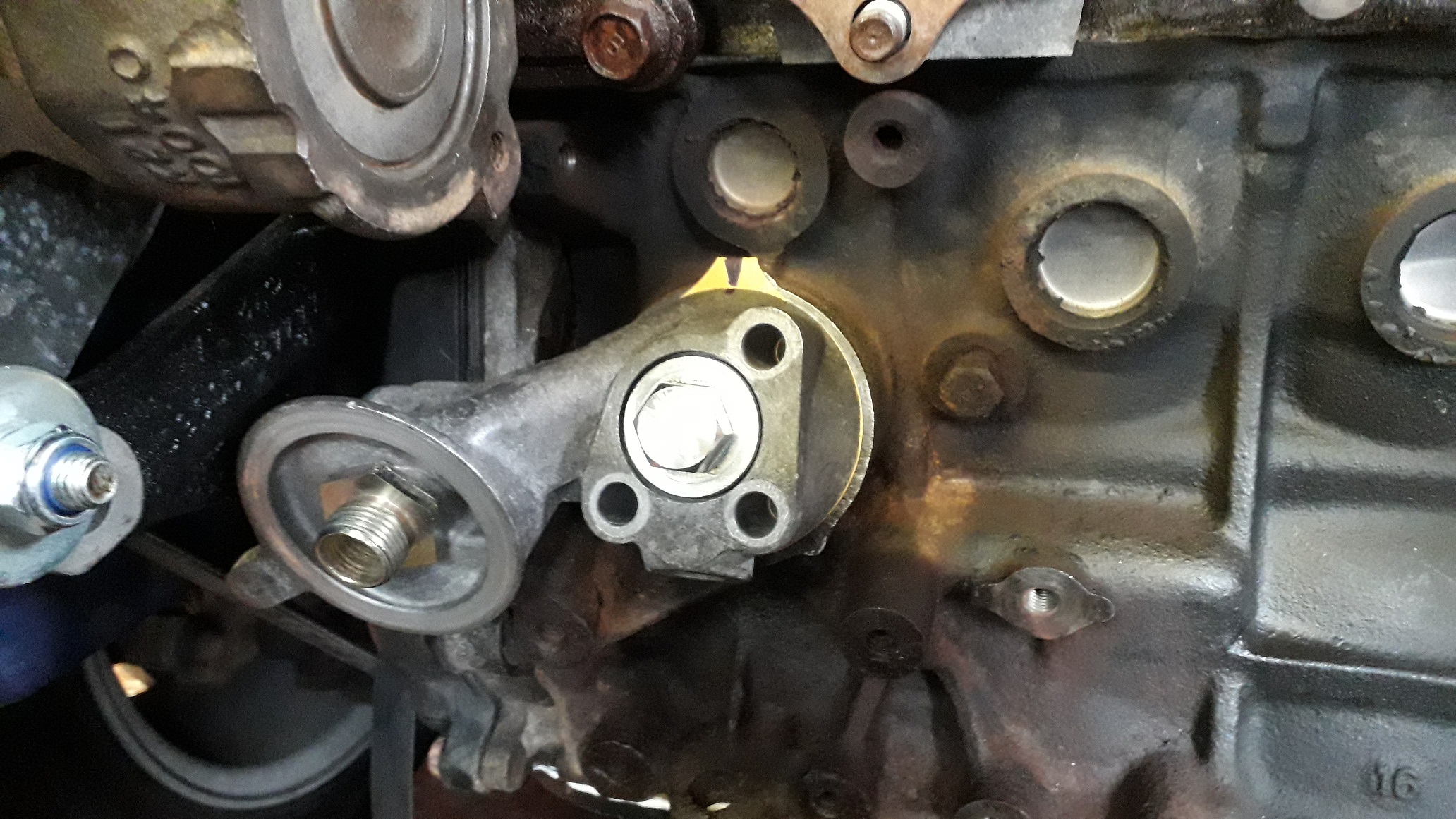
First needed to remove the 4efe oil filter banjo stud (?) I used a 12mm hex drain bit. It wouldn't fit initially so I has to round the corners off with a file then it slipped in nice.


The area around the filter got a bit of a clean up to remove the corrosion outside the filter seal as the gasket for the filter relocator is a larger diameter. Masked off, half done.
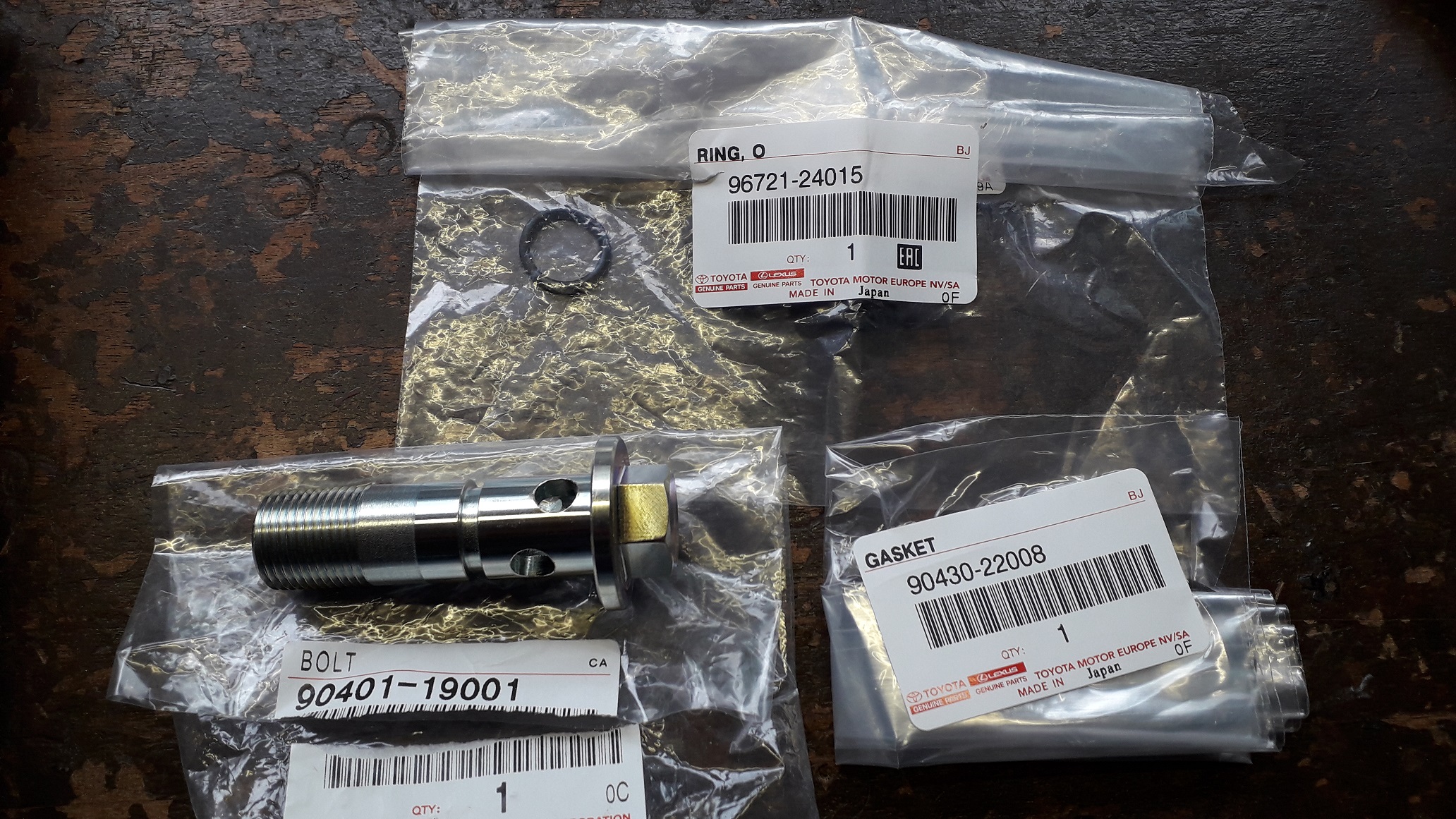
Assembled the new relocator banjo bolt (90401-19001) with a new O-ring (96721-24015) and bolt gasket (90430-22008).

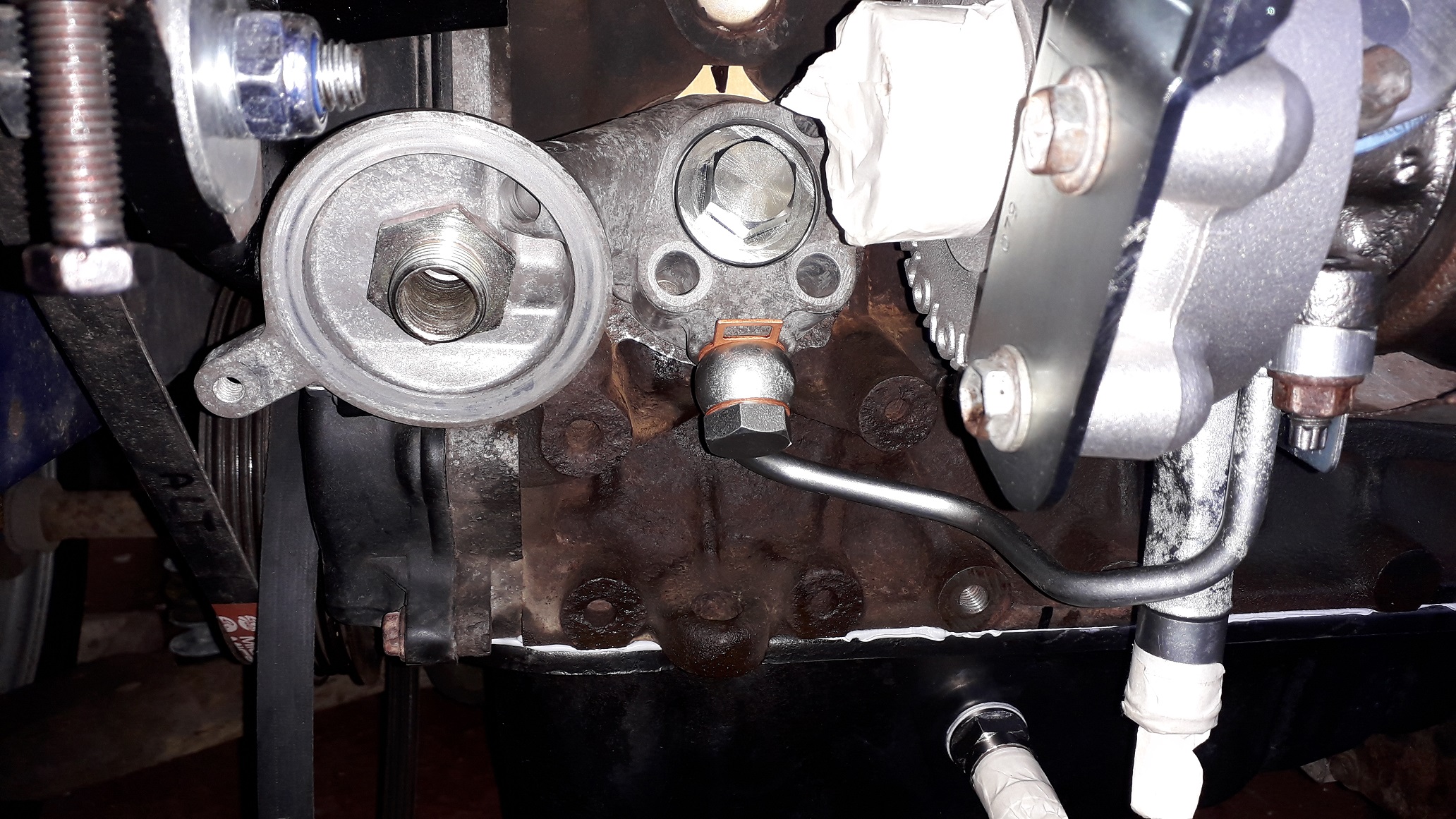
Used spray mount to stick the block gasket to the sealing face as I don't have 3 hands (cue total recall gag) and attached the relocator loosely with the banjo bolt. I marked the gasket and housing for alignment purposes, as the gasket has a unique shape to match the block and relocator and I won't be using the stud holes to locate it.

Used a new M14 oil feed banjo bolt (90401-14091) with copper crush washers. (90430-14006 Upper washer, 90430-14235 lower washer.)
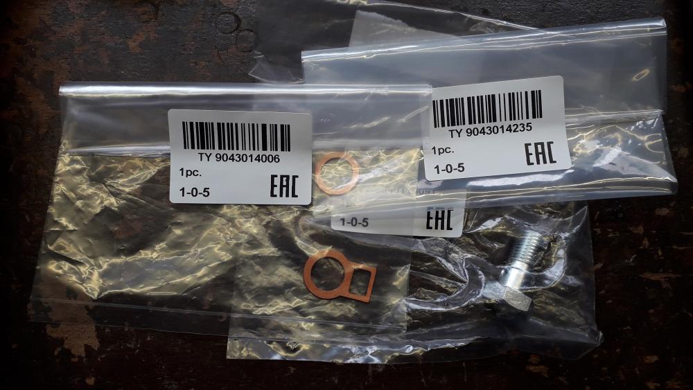
Refitted the mani / turbo and jiggled it all into position so the oil feed banjo bolt was installed, and tightened it all down. Both the banjo bolts are a 19mm hex and the upper copper crush washer has a handle of sorts attached to make locating it easier, nice touches from Toyota.

Filled a fresh filter with oil and screwed it on til it touched down and then another half turn to seal.

A good amount of room available for air filter pipework now. Re-filled the engine with 10w40 semi synthetic for its first oil change. Will attach the turbo oil return pipe to the sump fitting tomorrow.
")
-
Good work mate
-
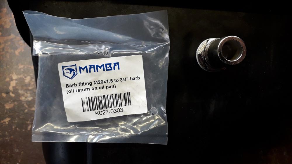
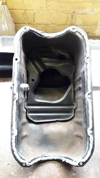
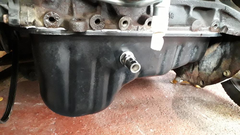
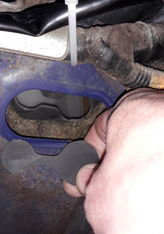
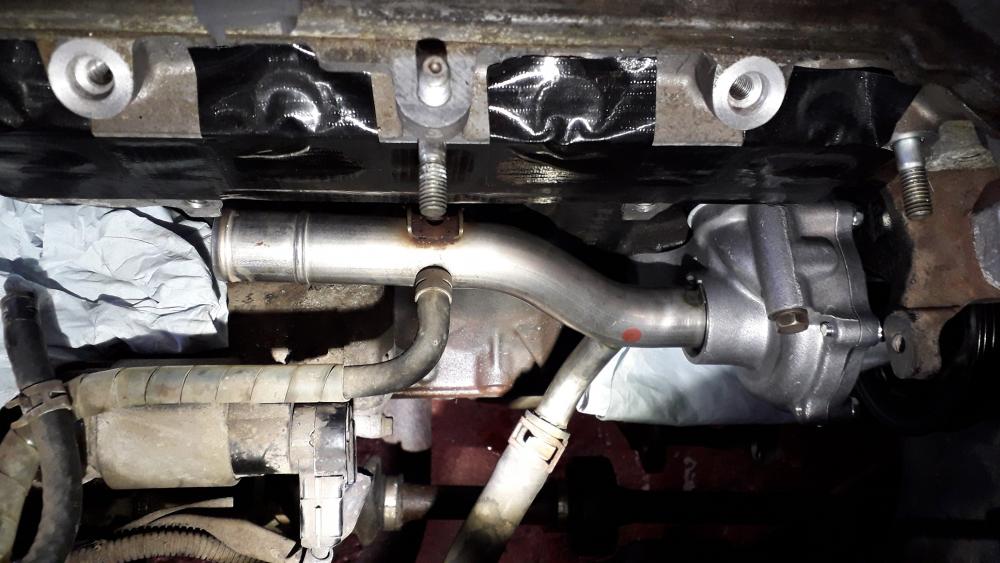
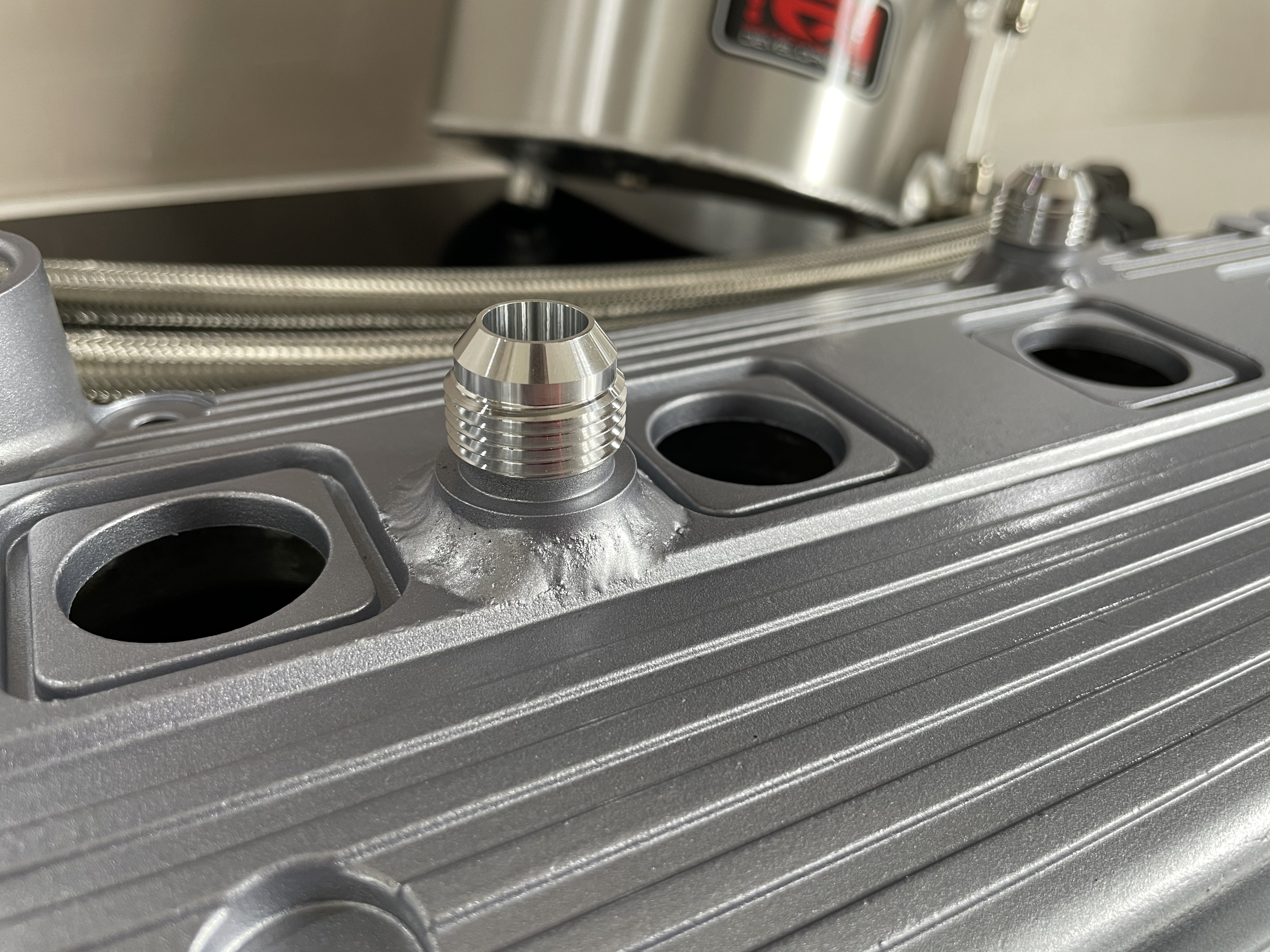
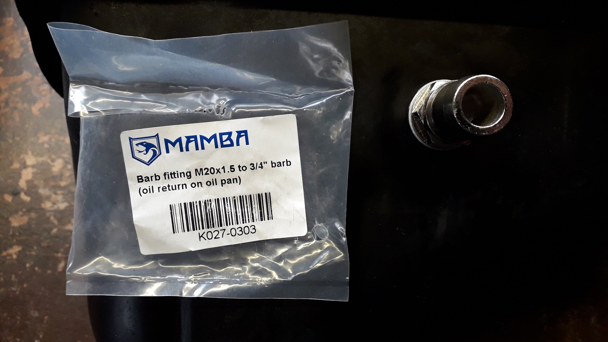
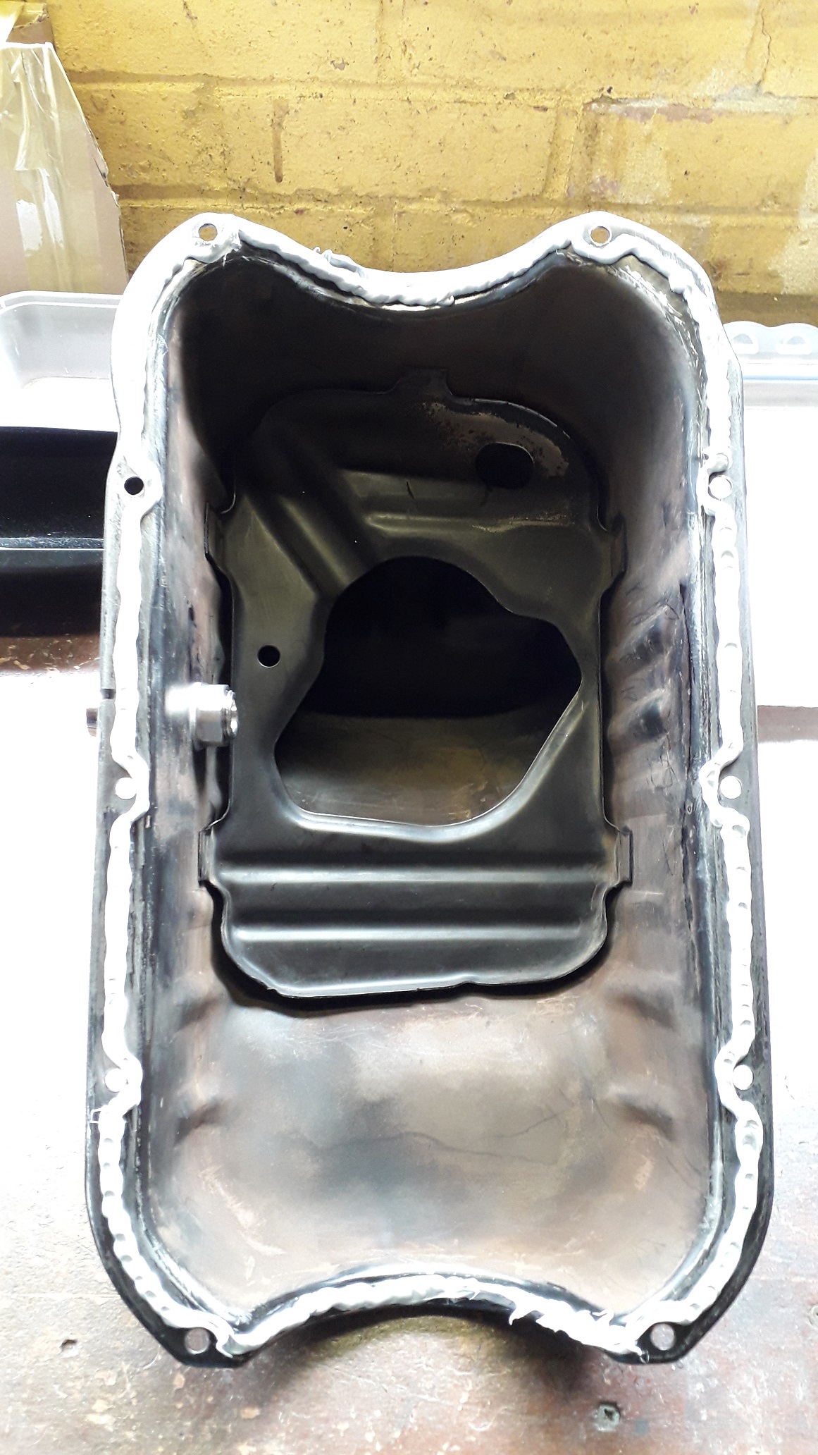
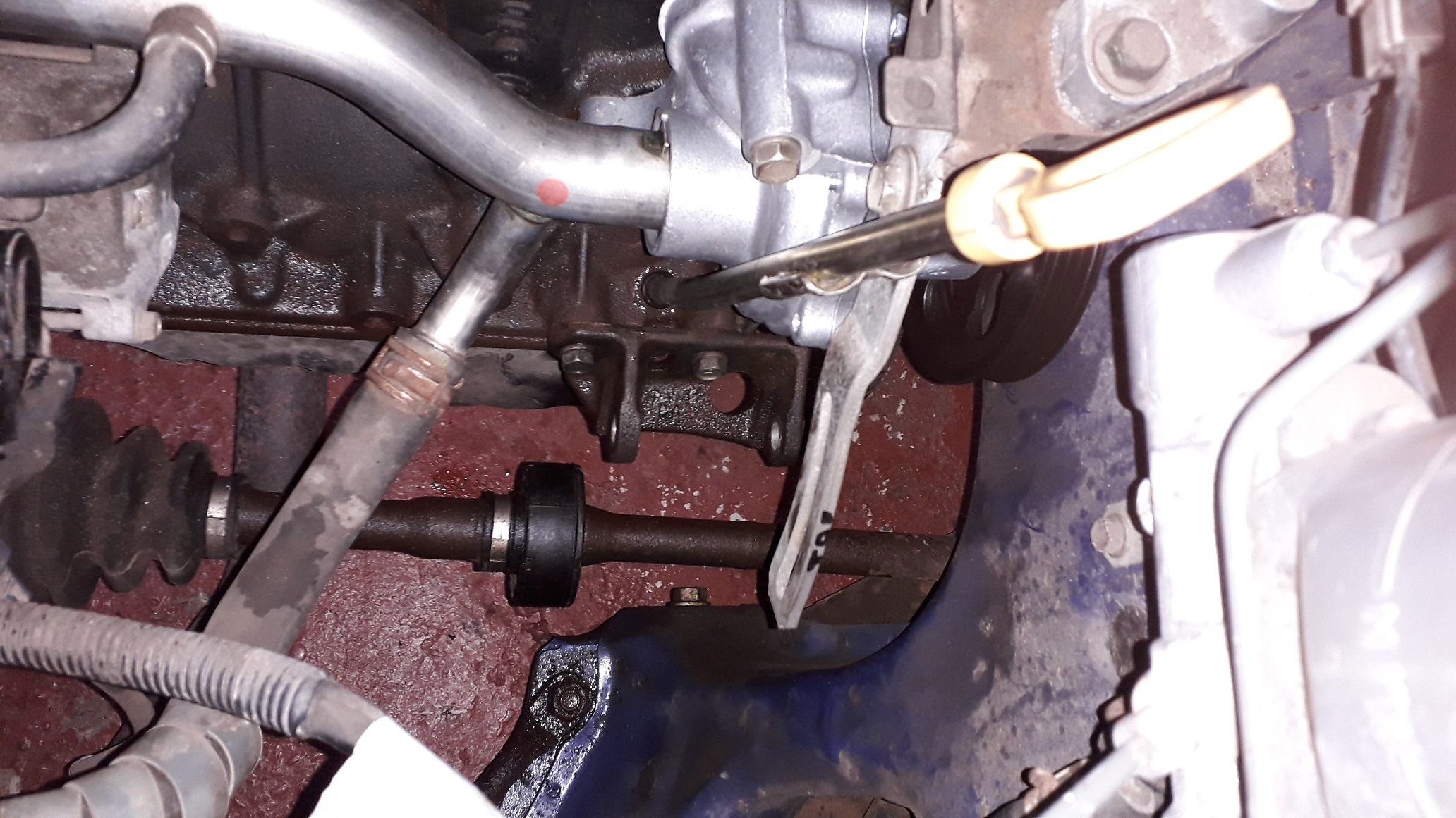
Sump oil return fitting:
Bought a Mamba bolt in oil return 19mm hose barb, M20 threaded end. (K027-0303)
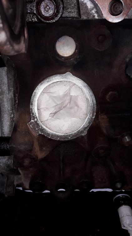
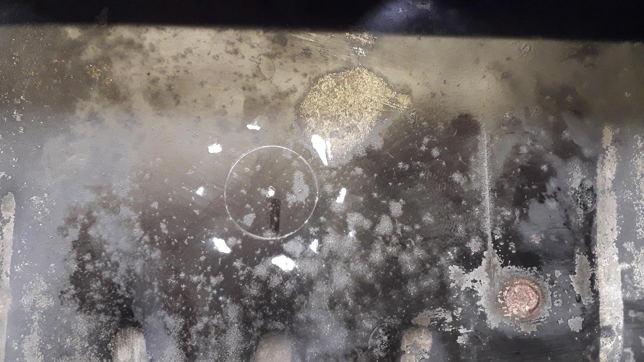
Centre punched the hole position to be drilled.
Using a step drill I began drilling with an old aerosol cap held on the other side of the pan to catch the swarf and stop it entering the pan. Thankfully the cap was deep enough that I didn't break through and drill my fingers! Much less mess to clear up.

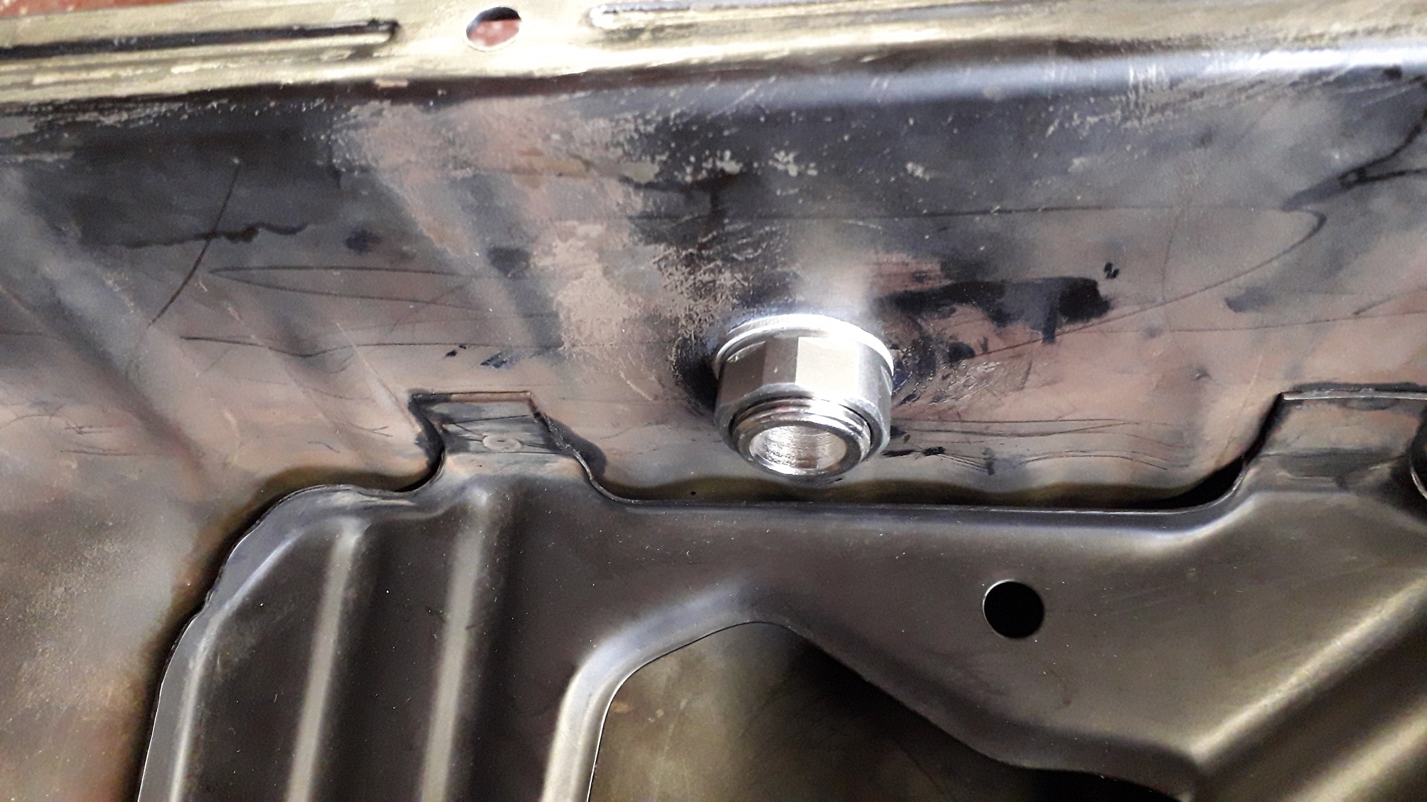
Deburred the hole, gave the outside a quick once over with satin black and heated with a paint stripper on low to help speed up the drying process. Then assembled the return fitting. The fitting comes with 2 x dowty seals (steel and rubber bonded washer / seal) but as you can't really tighten these to any real torque I replaced them with 2 x M20 alu crush washers, one either side of the pan. Added a bit of sealant for good measure around the hole first and than added the fixing nut (with threadlock!) and tightened to 45Nm as it felt "right". 22mm spanner and 24mm socket.

Degreased the block and pan sealing surface, vacuumed out the pan (just in case!) and added a 5-6mm bead of silicone sealant as per the rebuild manual (Elring Dirko again, only used half a small tube).
Threaded the pan back into position, feeding the flywheel end into the pocket in the blanking plate first. Pressed sump to block and added the screws tightened to 8.5Nm from the centre out (10mm socket).
Glad its done, not a fan of sealant and much prefer gaskets as you get more time to work and reposition. Felt like it went on well so I'm going with that.
-
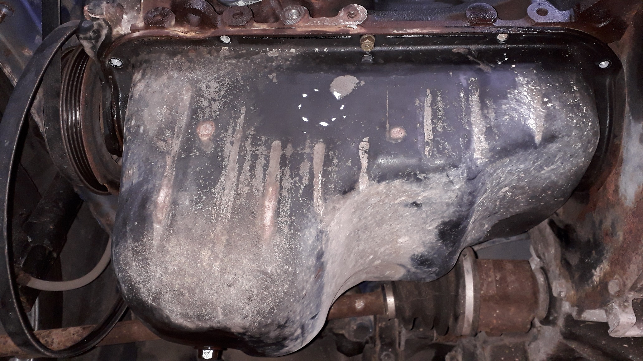
Sump turbo oil return:
Needed to have a fitting in the sump to return the oil from the turbo, didn't fancy trying to find a 4efte version that wasn't dented and the matching pickup so thought I'd add on to the existing 4efe item.
Started by removing all but the 2 centre bolts holding the sump to the block, Just loosened these to help "catch the sump during removal.

Tapped a small flat blade screwdriver in between the parts to split them. Needed to be careful not to scratch the mounting surfaces. Repeated for rear corner.

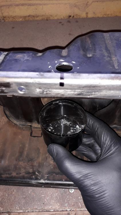
Unthreaded the pan from the oil pickup, lowered the pan straight down pretty much. The engine has a similar amount of varnish to the cam cover.
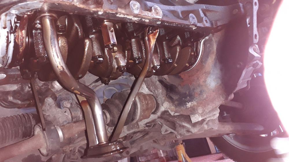
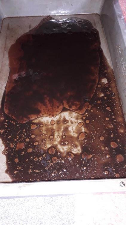
Even though I had jacked the car up to empty the sump there was still a cup of coolant / oil left in the bottom! Glad I needed to remove it.
. No cam shrapnel found either.
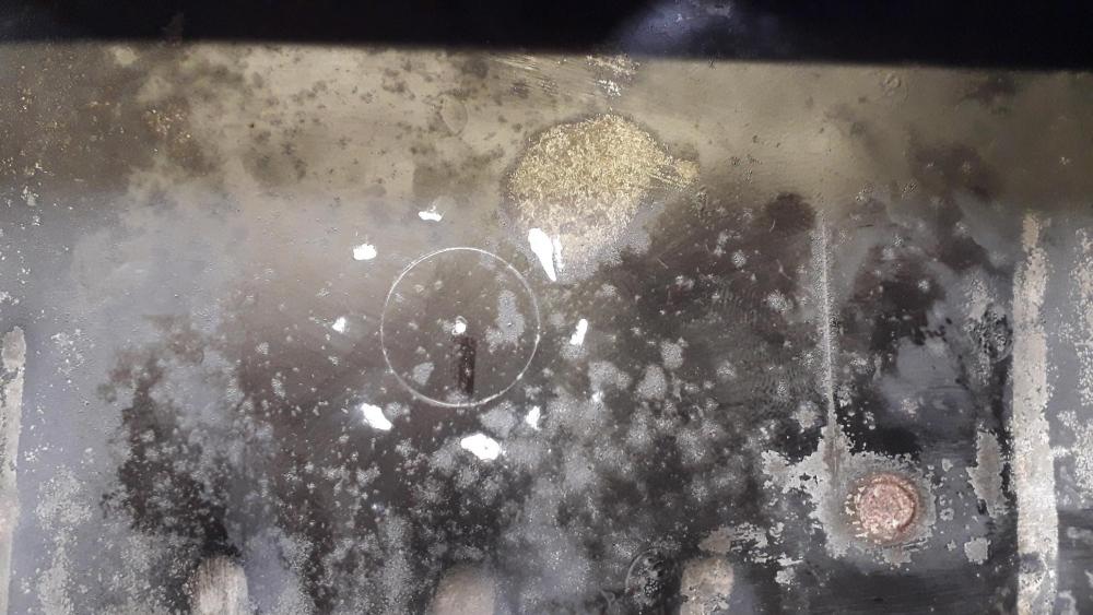
Cleaned up the pan surface to remove the old sealant with a stanley blade and wire wheel on a drill.
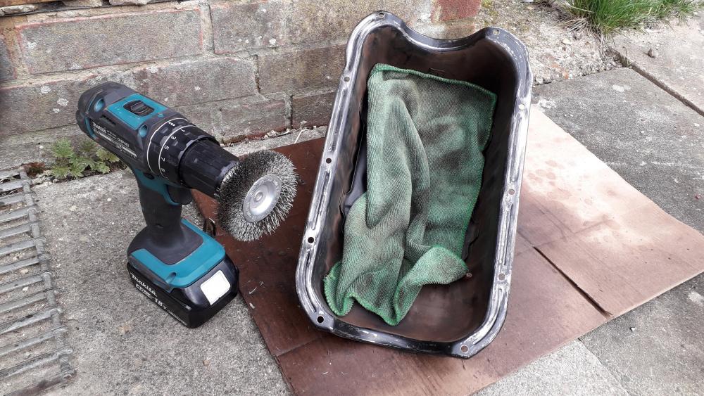
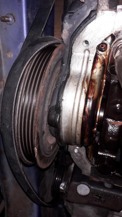
Cleaned the block / oil pump / main seal carrier with a blade and small blunt screwdriver. The grooves in the oil pump and / /carrier were the most time consuming but after an hour of lying under the exposed engine with oil and sealant debris raining down it was clean enough for reassembly.

-
On 3/31/2021 at 5:10 AM, Sam44 said:
Now your talking.
Looking super sexy lad. Keep it coming
Thanks mate.
On 3/30/2021 at 10:59 PM, Pikey009 said:Ha, this is like watching my own thread! Or at least it will be when I update it. Also having intercooler trouble due to an aftermarket manifold.
the eBay stuff never fits does it. Good progress though.
Yep, eBay tat is par for the course it seems. I just can't justify top money for parts for a relatively cheap / low boost build. It seems that here are no mid priced mani and downpipe combo's out there worth buying, its either top end artisan creations or utter shite from the Far east.
If I can find anything decent second hand I'll replace the downpipe ASAP. The mani and turbo are spot on as Toyota parts should be. Might linish the dpipe lower flange to a better angle when the enthusiasm has returned.
Sump oil return next.
")
-
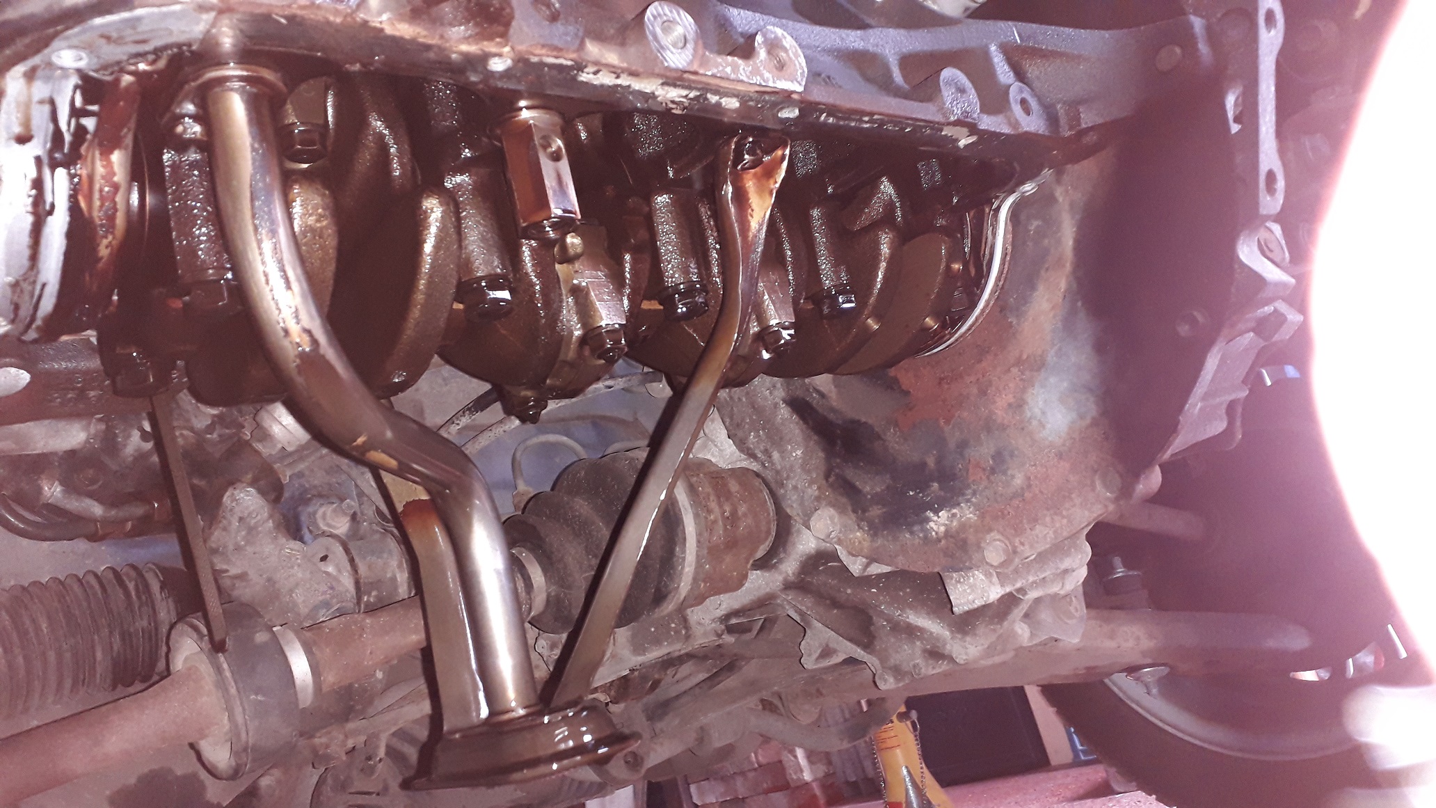
Downpipe fitment / modification

As usual I bought the cheapest downpipe that included a brace. It was a Gravity branded piece of shit from eBay.
The turbo flange fitted ok to the turbo, the centre exhaust flange is angled slightly and also rotated slightly from where it should be and the bolt holes to mate to the centre section were very wrong! Also the brace plate was at an incorrect angle to the Toyota block brace. I knew it would need some mods but didn't think it would be this bad.
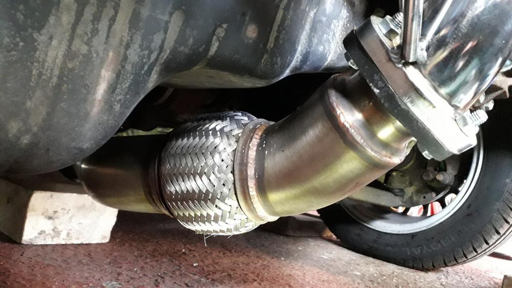
So I filed out the centre section mount holes to allow fitment of the centre using M 8 bolts. The extra room allowed me to twist the centre exhaust to be clocked correctly. Clears the sump, ground clearance reduced.
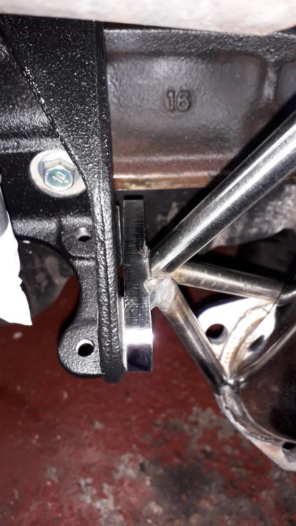
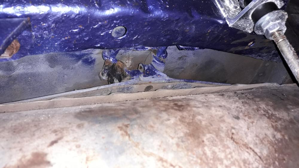
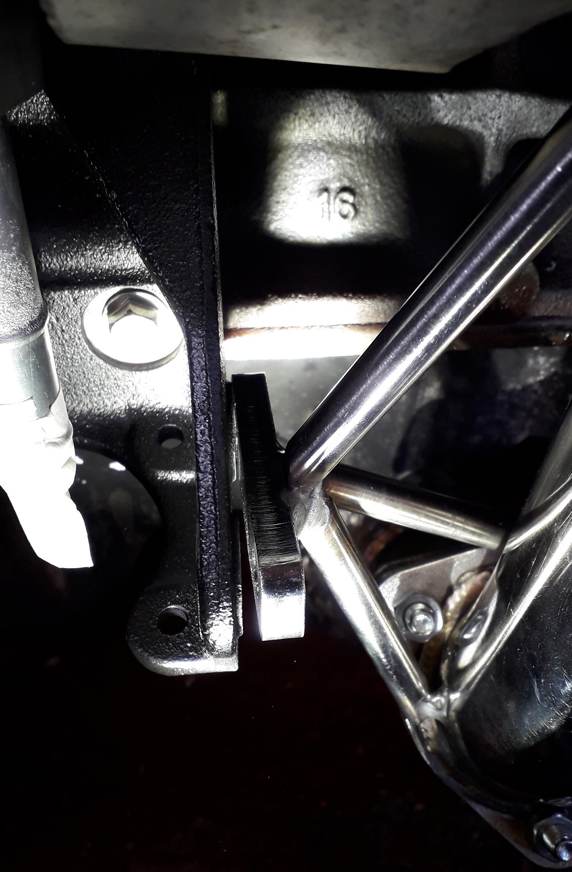
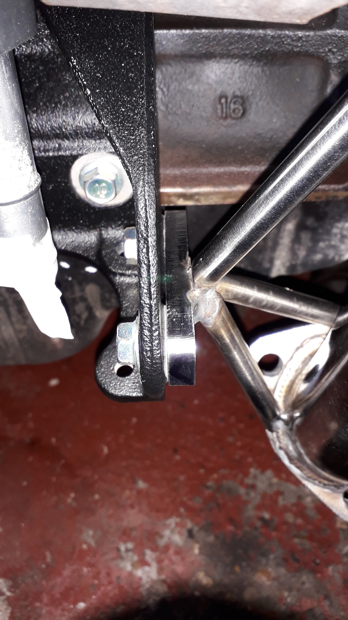
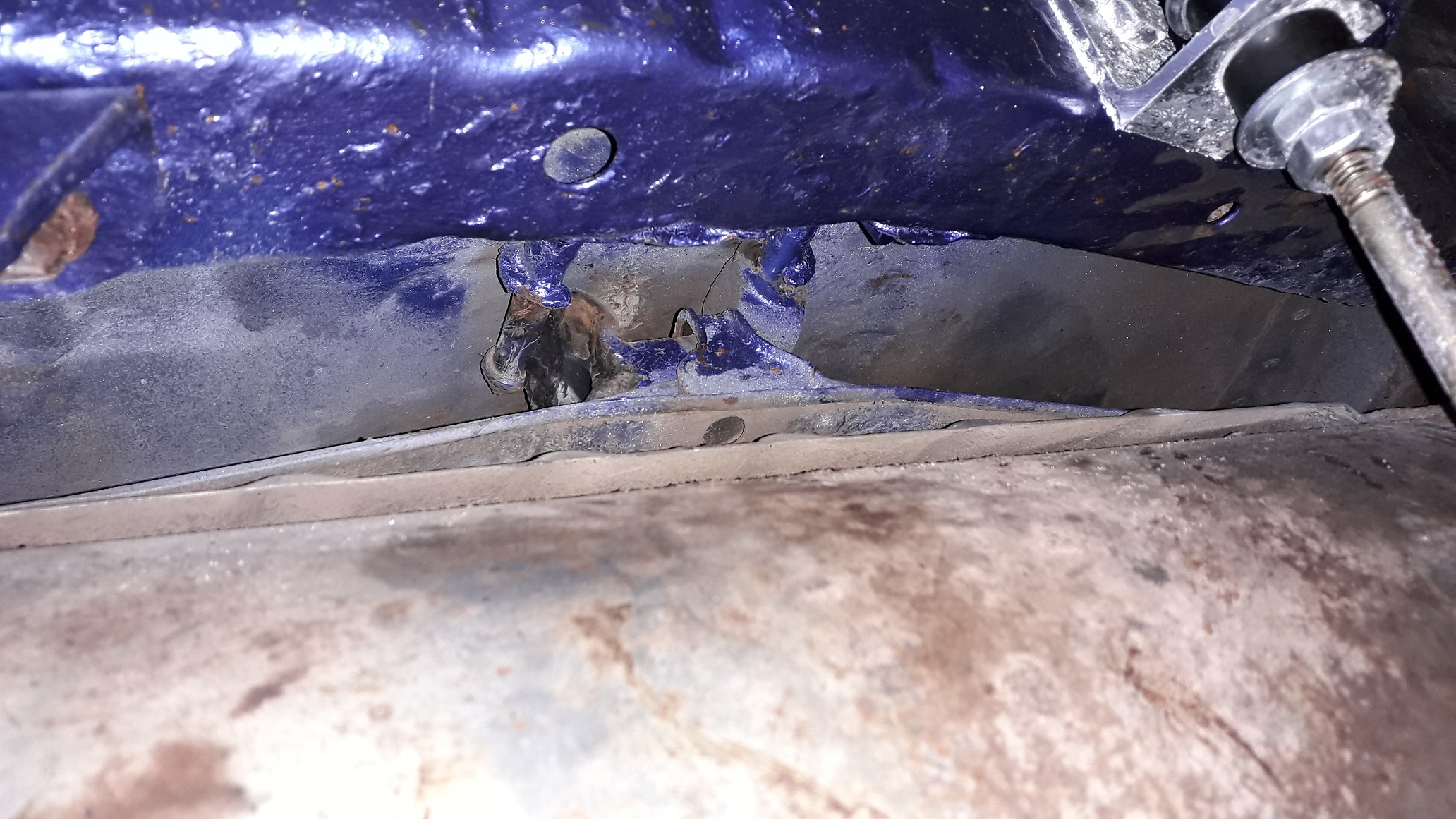
Then I fitted it to the turbo and the brace plate looked like this:
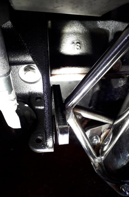
There was no way of adjusting the error out, so I removed the downpipe, cut through the welds holding the brace plate to the rear 2 support bars and gently "realigned" the plate with a 2kg hammer. A bit too far it seemed!
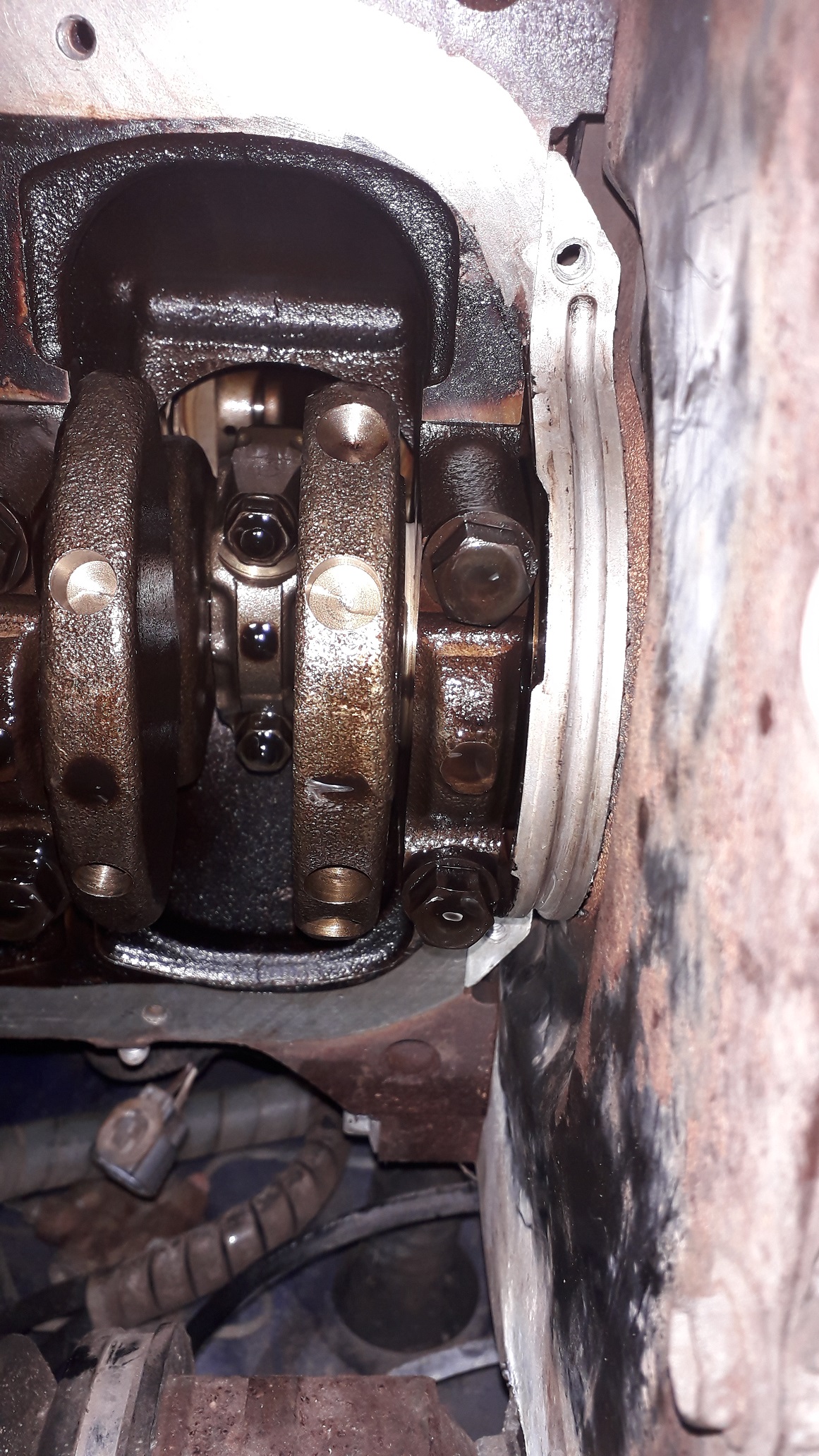
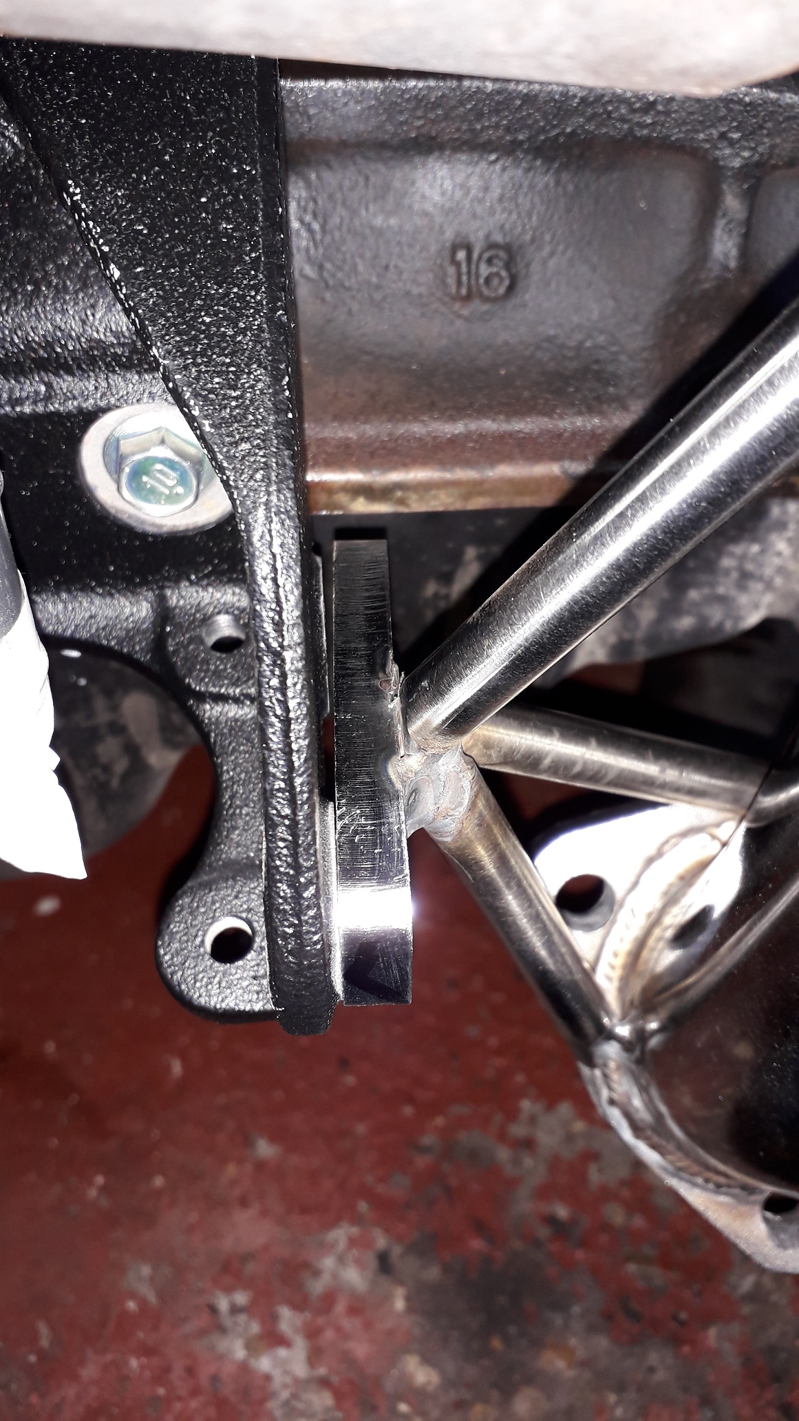
A bit more "adjusting" later the plate followed the brace angle nicely so I removed it again and welded the plate back to the rear 2 support bars.

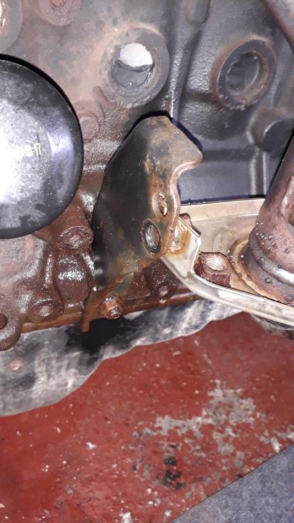
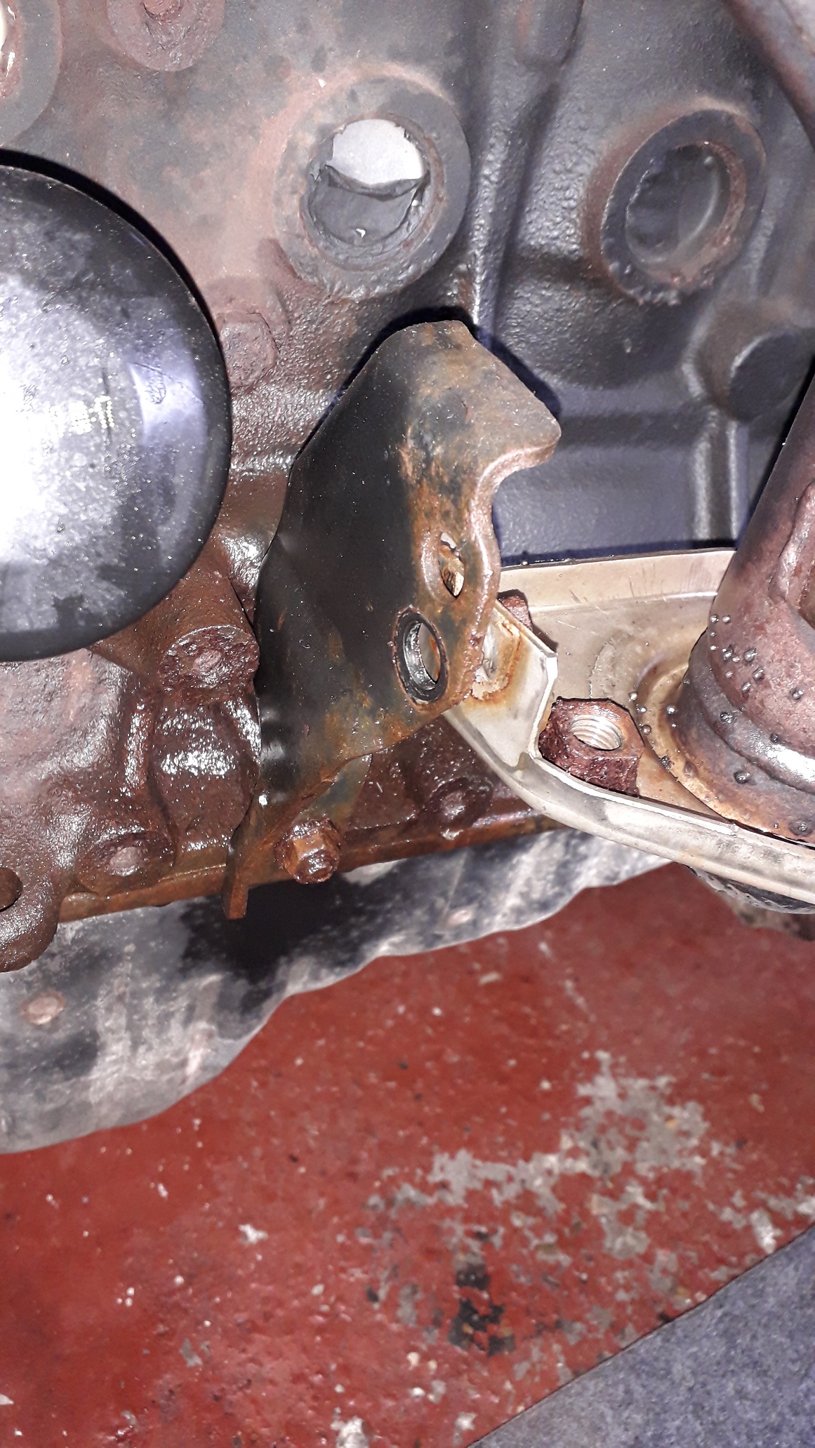
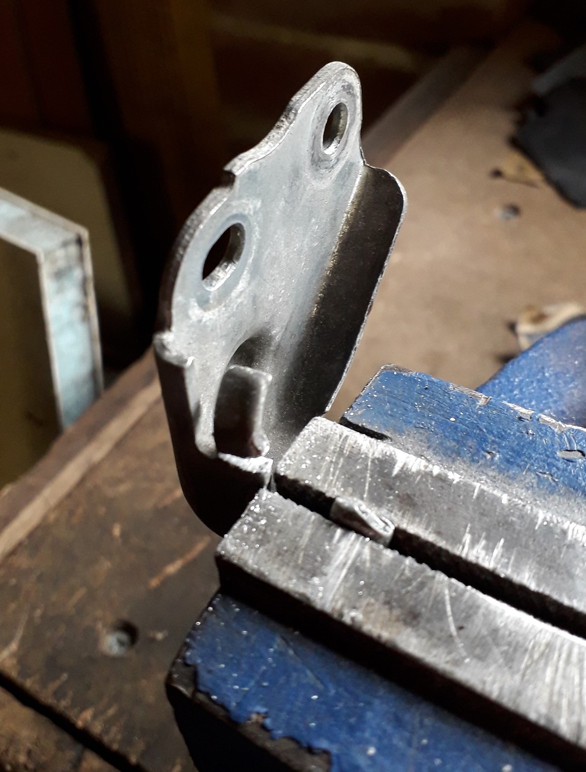
Also, if you ever wondered what the semi circular impression in the drain tube was for....it allows access to the upper block brace screw.

So from manifold to centre exhaust section is acceptable now. The exhaust is for a Glanza and as the front mounting posts are in a different place on the chassis from Glanza to N/A its gonna need a custom mount making. Thanks Toyota! 🖕
Also had a test fit with the intercooler hot pipe that I need to mod aswell. Yay more work!

-
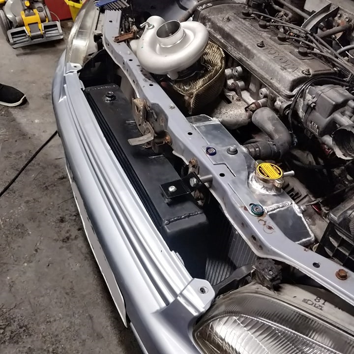
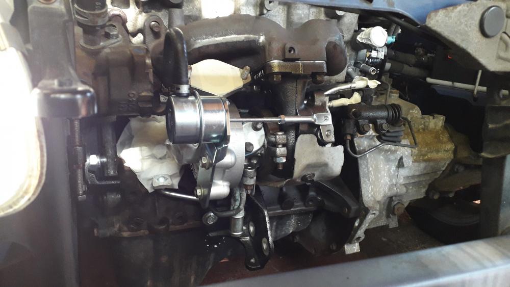
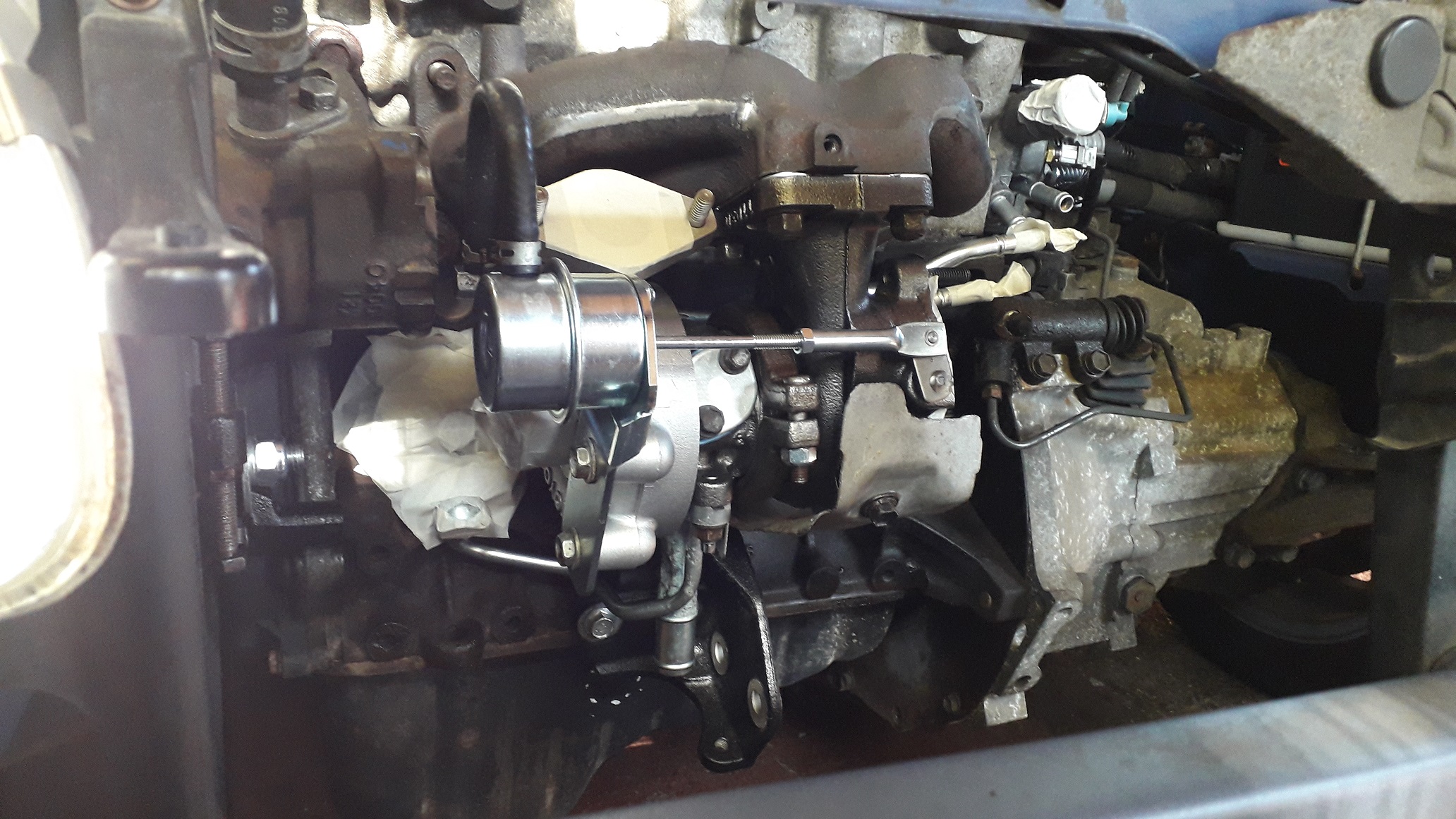
It's Turbo Tuesdaaaaaaaaay!

Next up was the test fit of the turbo to work out sump oil drain position and to check the Downpipe fitment.
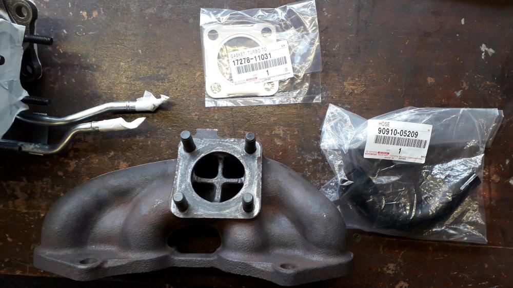
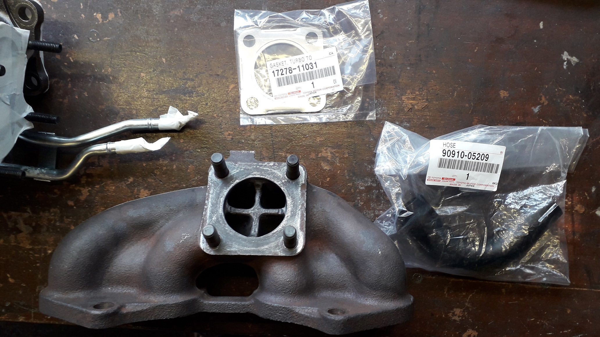
Assembled the CT9a to the ported cast manifold with a genuine Toyota gasket (17278-11030)
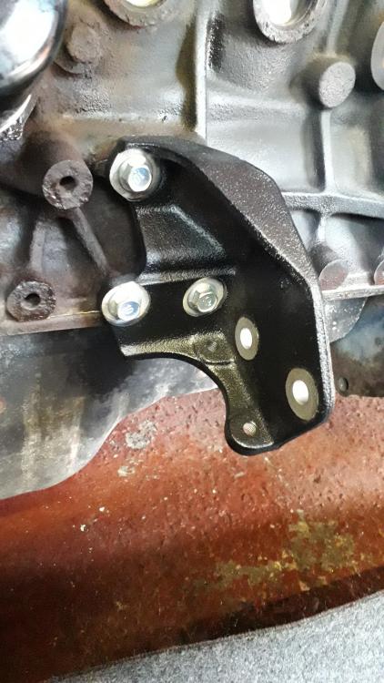
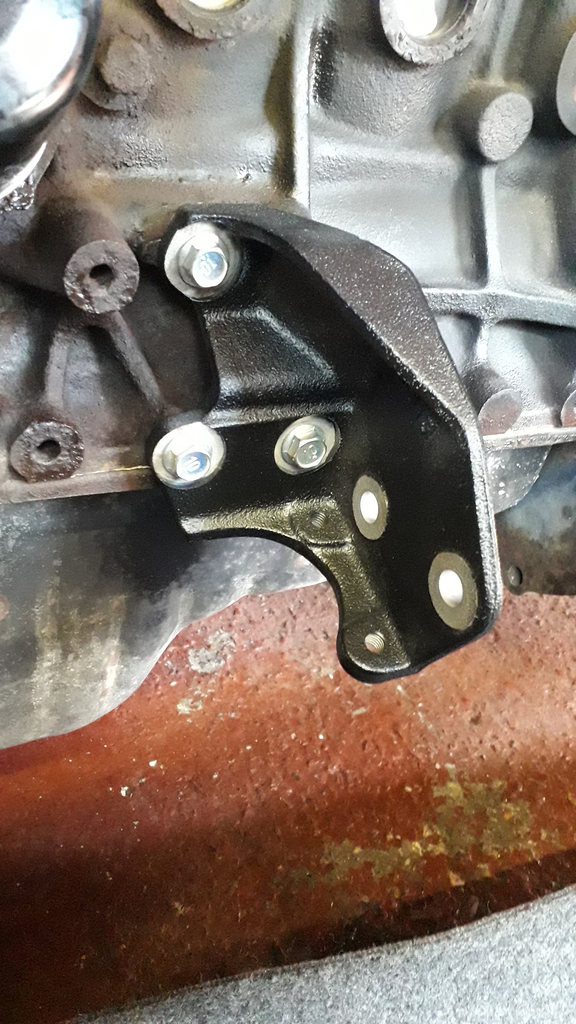
Fitted the downpipe support bracket to the block loosely as it would need adjusting to meet the downpipe bracket. There is quite a lot of movement available as the mounting holes are nicely over size.
Cleaned up the head mating surface and the old gasket with a stanley blade (trial fitment) and bolted the turbo and manifold combo to the head for the first time. 😁
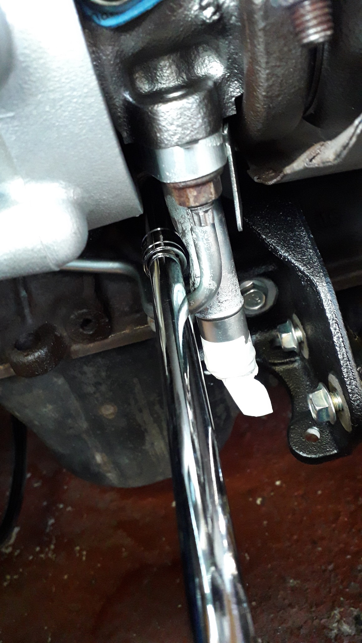
Fitted the oil drain hose (90910-05209) to the standard return pipe to give me the position that the return bung needed to be at. Marked the position on the pan for later.
Downpipe next.
-
Some minor progress: treated the rust patch on the chassis that was accessible with the exhaust removed, realigned the drivers door after the new hinge I installed back in the summer had "bedded in".
Also trial fitted the 4efte injectors and discovered something interesting.
The EP91 4efe injectors use the same rubber spacers and lower rubber seals as the EP91 4efte. The injectors are the same length and the only part number differences are for the rail and the rail posts (mid -96 on).
When I removed the fe injectors the seals were knackered so I replaced them with the used 4efte items and when fitted to the head it is apparent that there was a gap between the rubber spacer and fuel rail and the injector could be pulled up out of the head!
FE injector shows gap
FTE injector shows gap
Both types of injector are 48.Xmm long. The fuel rail posts are 38mm long.
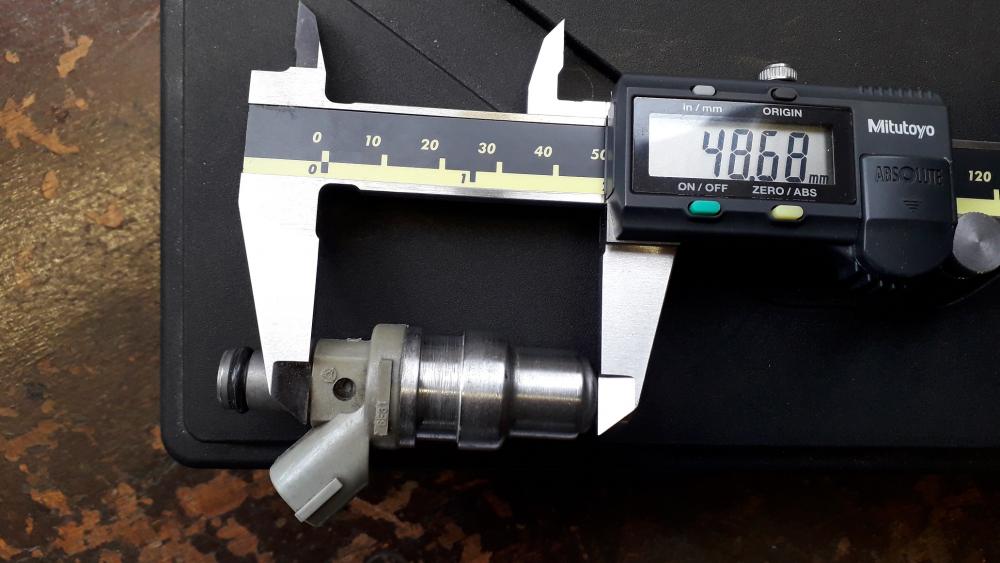
So assuming the lower seals I got with the fte injectors are infact the correct items (you never know second hand) it looks like the 4efte fuel rail presses the injectors approx. 2mm further into the head than the 4efe. It may be achieved with shorter fuel rail posts or differences in the rail geometry or a combo of both.
I have ordered a new set of rubber spacers and seals and hopefully a fresh set will have enough compression on the 4efe rail and posts to seal well enough for boost. I could well have been supplied the wrong old seals also but we shall see. Also the fte injectors are what everyone seems to use so not worried yet!🤞
If anyone with a Glanza fancy's helping out I would appreciate it if they could measure the length of the fuel rail post from head to underside of fuel rail to see if there is a difference? Obviously no need to take anything apart, just measure.

-
12 hours ago, burty said:
Wow mate so much information and attention to detail this sleeper is gonna be up there with the best if not the best
Cheers mate.
5 hours ago, Trevstar said:Dead smart! Might have to copy what you've done here as well 😅 good stuff mate! 👍🏻
Thanks mate, I'm flattered.

-
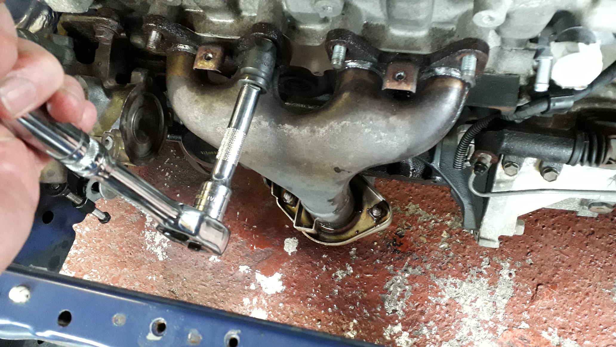
4efe exhaust removal
Started the process about a week ago by soaking all the fasteners in WD40 on a daily basis.
Managed to loosen of all the manifold nuts, and the bolts that connect the mani to downpipe without issue (14mm socket and breaker required at the start). Was dreading this part but all came good
") . Left assembled for the next step.
. Left assembled for the next step.

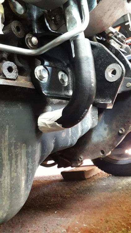
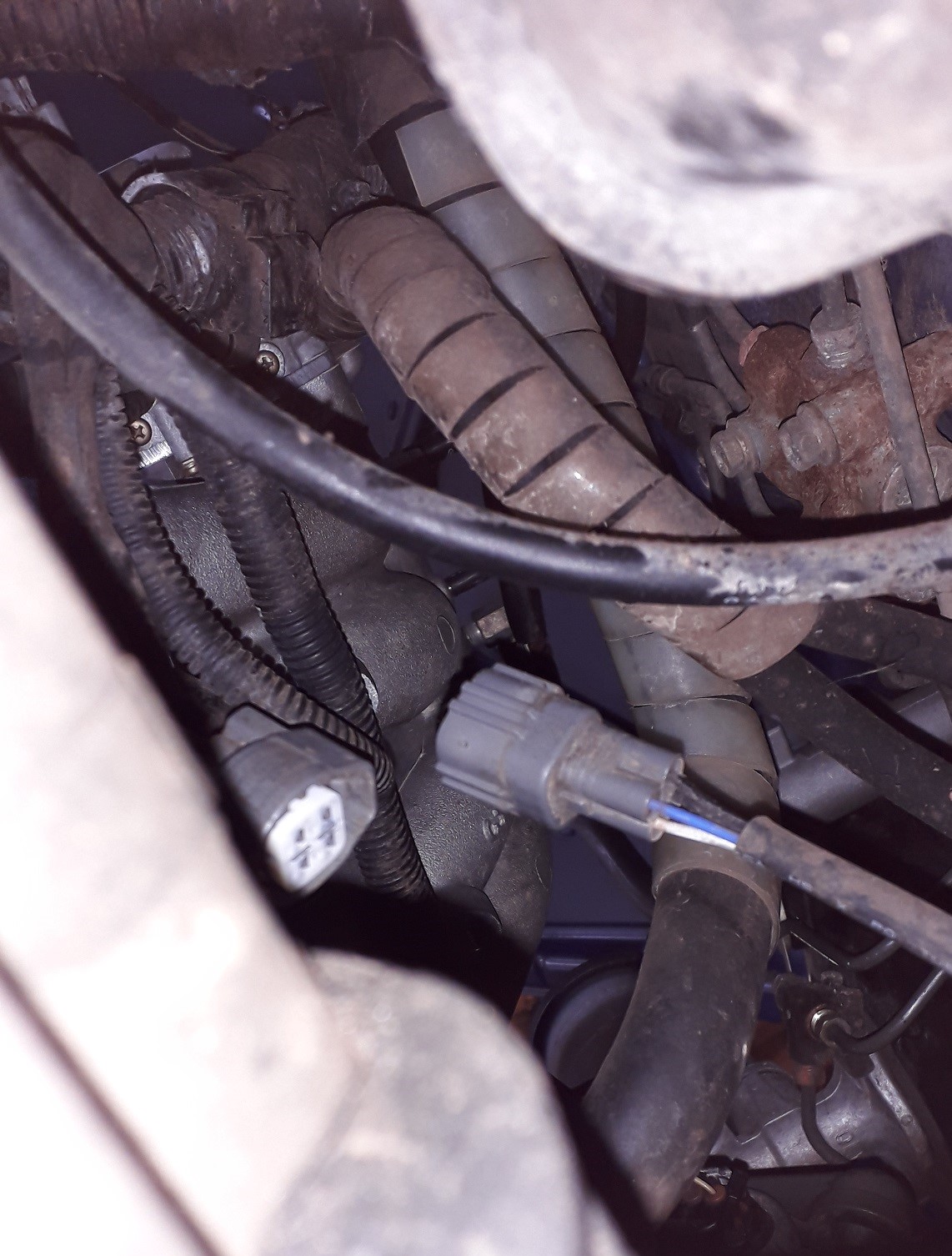
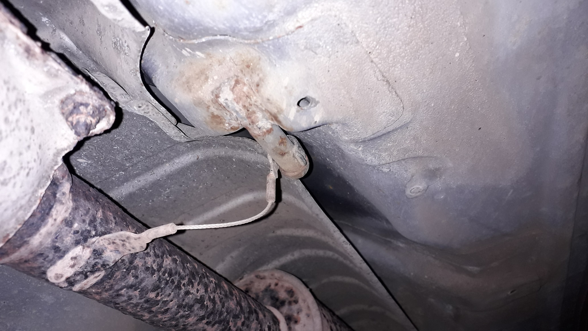
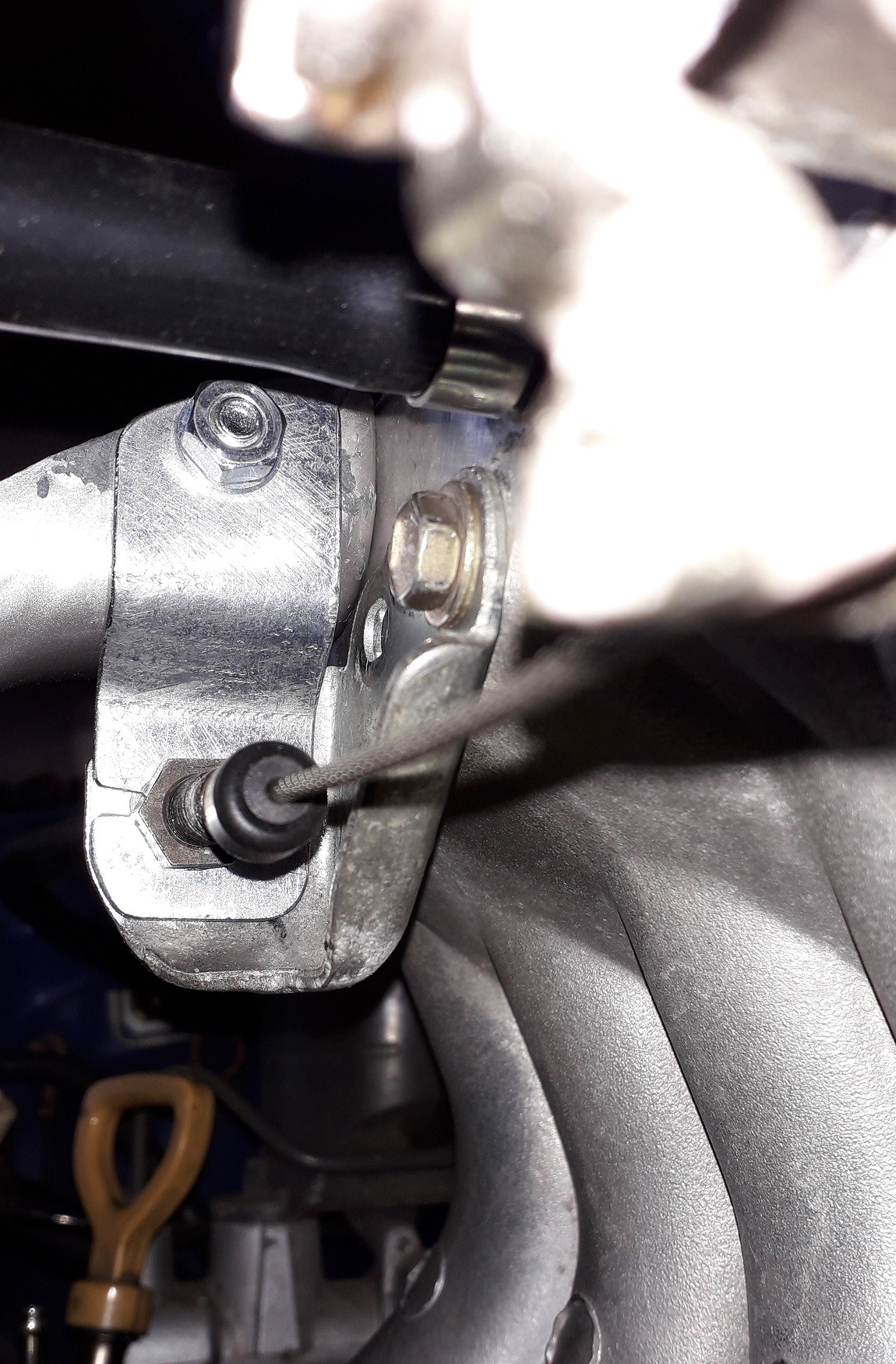
Disconnected the stock O2 sensor from underneath and pulled the rubber hangers off the exhaust mounts

Unclipped the cable thingy from its post
 (?!). Can only assume its for breakaway safety or as a movement limiter on the UK EP91. It was plastic dip coated so wouldn't have worked as an earth strap.

Removed the mani to downpipe bolts and lowered the front section to the floor. Moved onto the back box and after much thinking and careful prying to try and slide the rubber hanger off its posts, "monkey got rage" 🦍 and decided to just cut the fucking hanger in half!
Lowered the exhaust down and as the clamp to hold the back box to the mid section was rusted solid I once again opted for the rage solution and sawed the mid section in half. Slowly and carefully unthreaded the back box pipe from the panhard rod support and it was out.
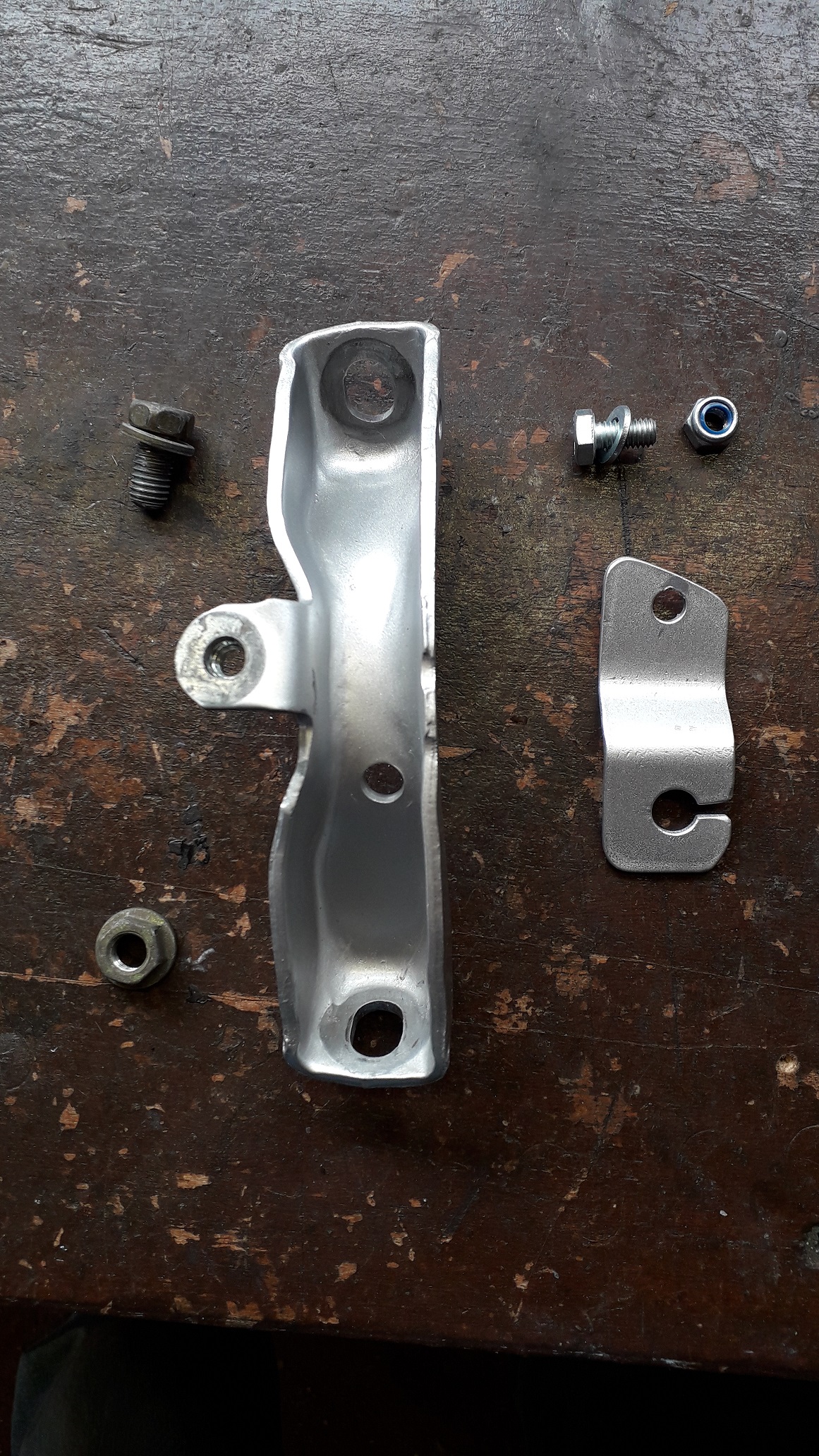
Removed the front downpipe support bracket with a 12mm socket (the 4efte downpipe brace fits to the same mounting points) and then removed the manifold.
Managed to get the O2 sensor out surprisingly easy with a 22mm brake pipe spanner. The backbox is in good condition but the centre section is heavily corroded anyway (hence the removal method). The cat should be worth a few quid in scrap also!

Now comes the fun part.....
-
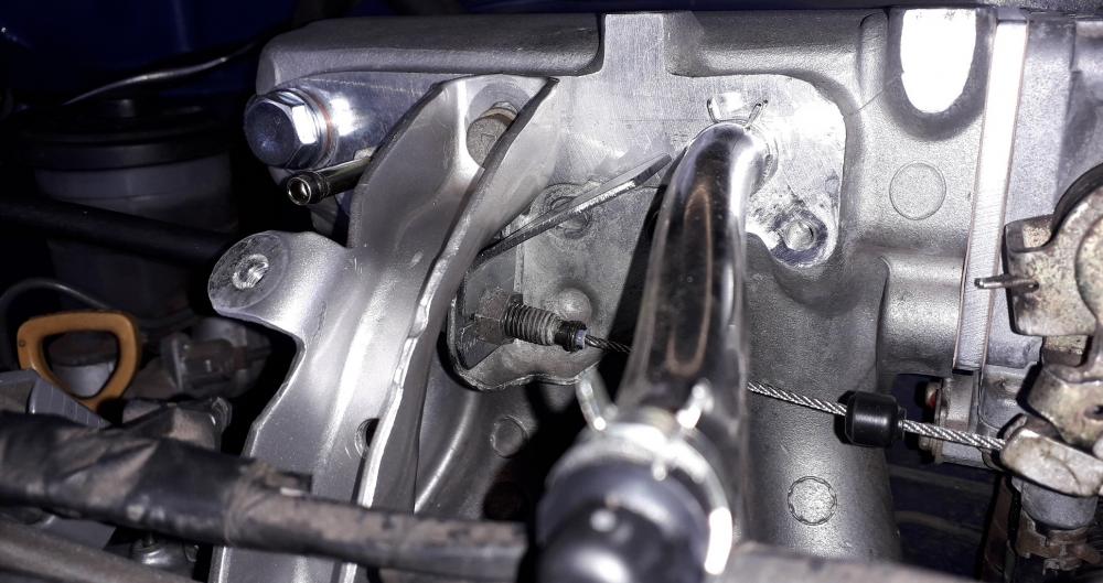
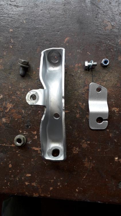
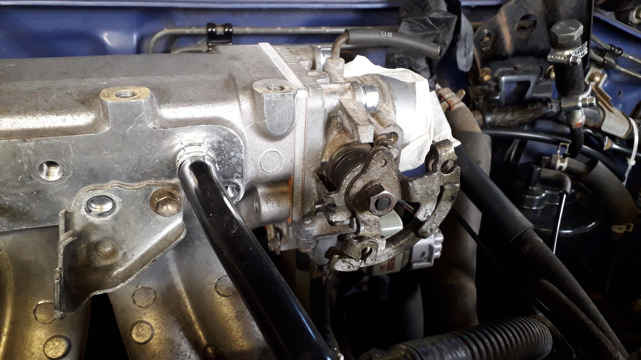
More brackets.......
Made a small dog leg bracket to secure the rear of the throttle cable bracket to the manifold to head bracket.
Removed the tab from the throttle cable bracket as it was in the way

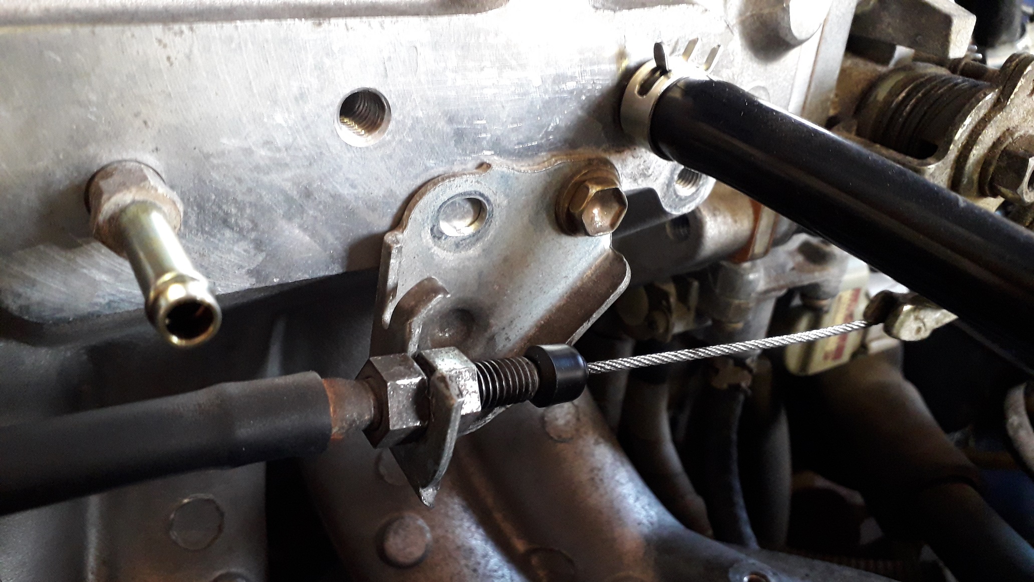
Using a strip of 2mm pre galvanised steel I drilled a 9mm hole for the cable sheath adjuster section and cut a slot so it can be slipped over the cable. First bend.
Removed from the manifold and made the second bend.
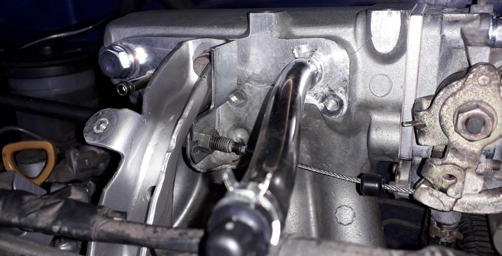
After much on and off and adjustment of the bend angles the bracket sat comfortably between the 2 mounting surfaces. Removed, then shaped the top end to match the curve of the head bracket and drilled the M6 attachment holes in both.

Painted, ready to install.
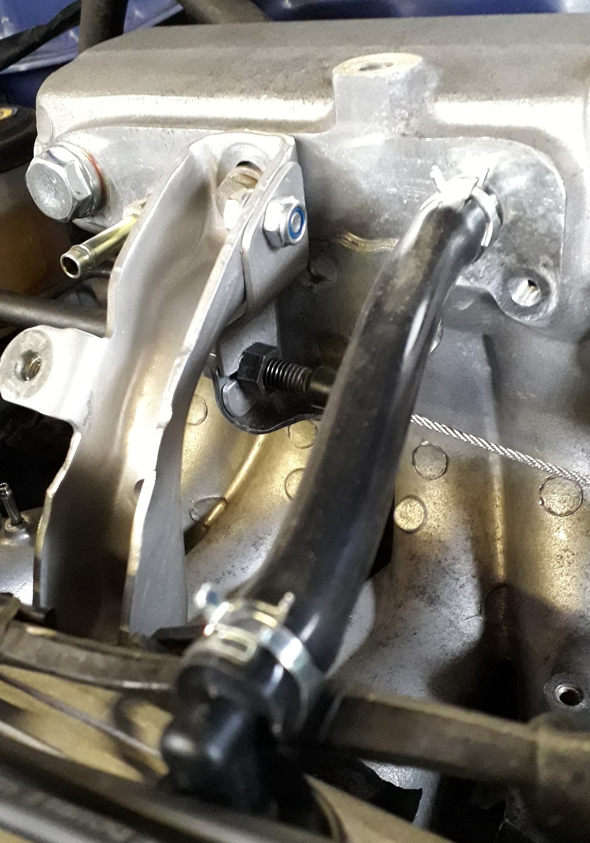
Installed the head brace first (20Nm), then attached the cable / dog leg bracket loosely, aligned the components and then fully tightened.
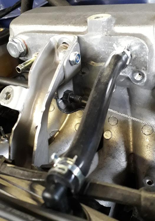
Much more secure / reliable.
-
Looking good Frankie, nice to know you have an engine on the way. Looking forward to the build thread. I'm doing fine and cracking on with my build. Hope you and your family are well.
-
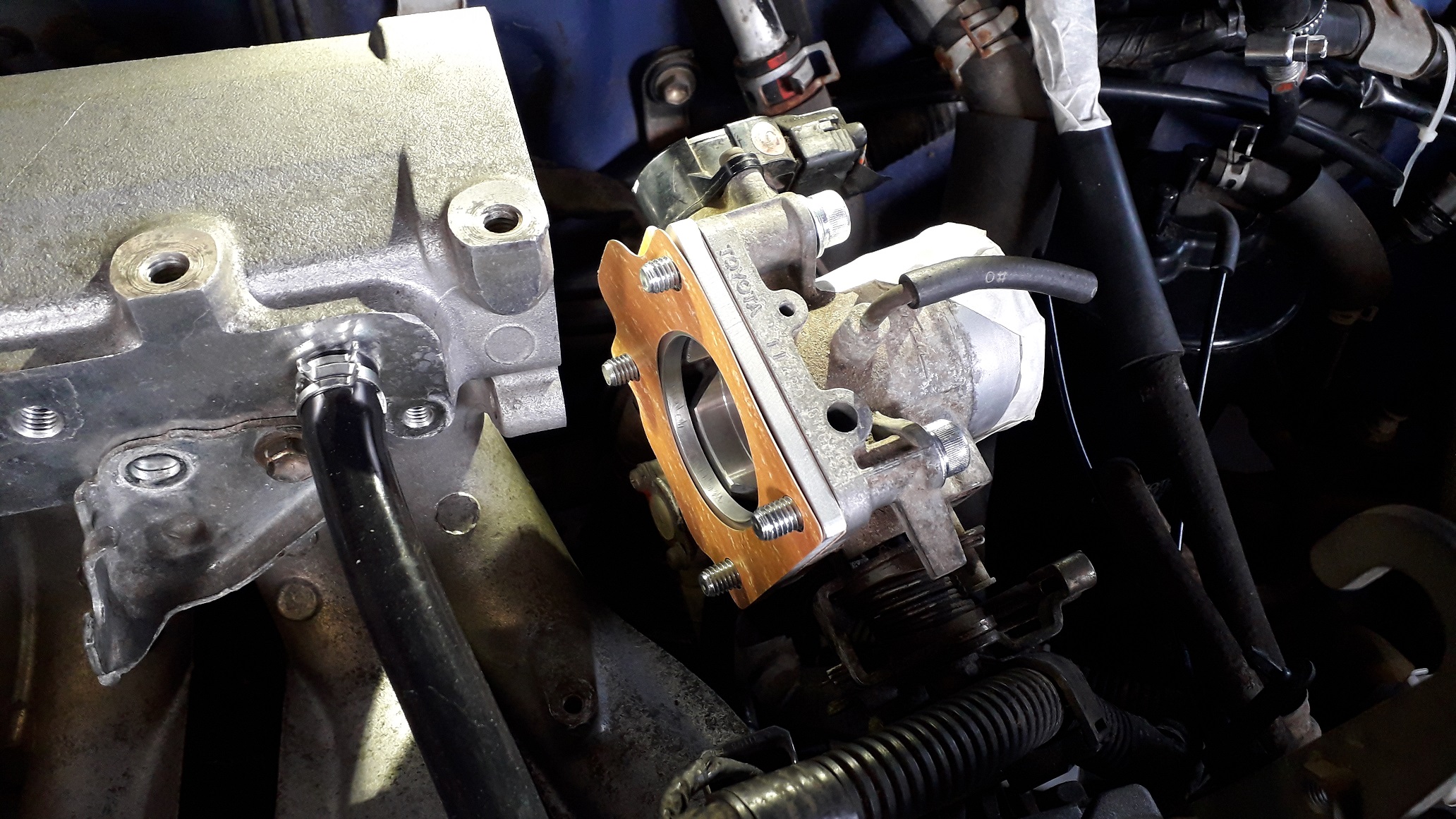
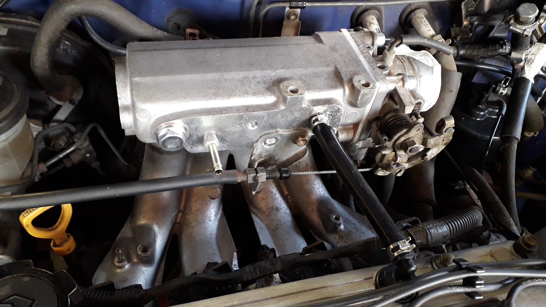
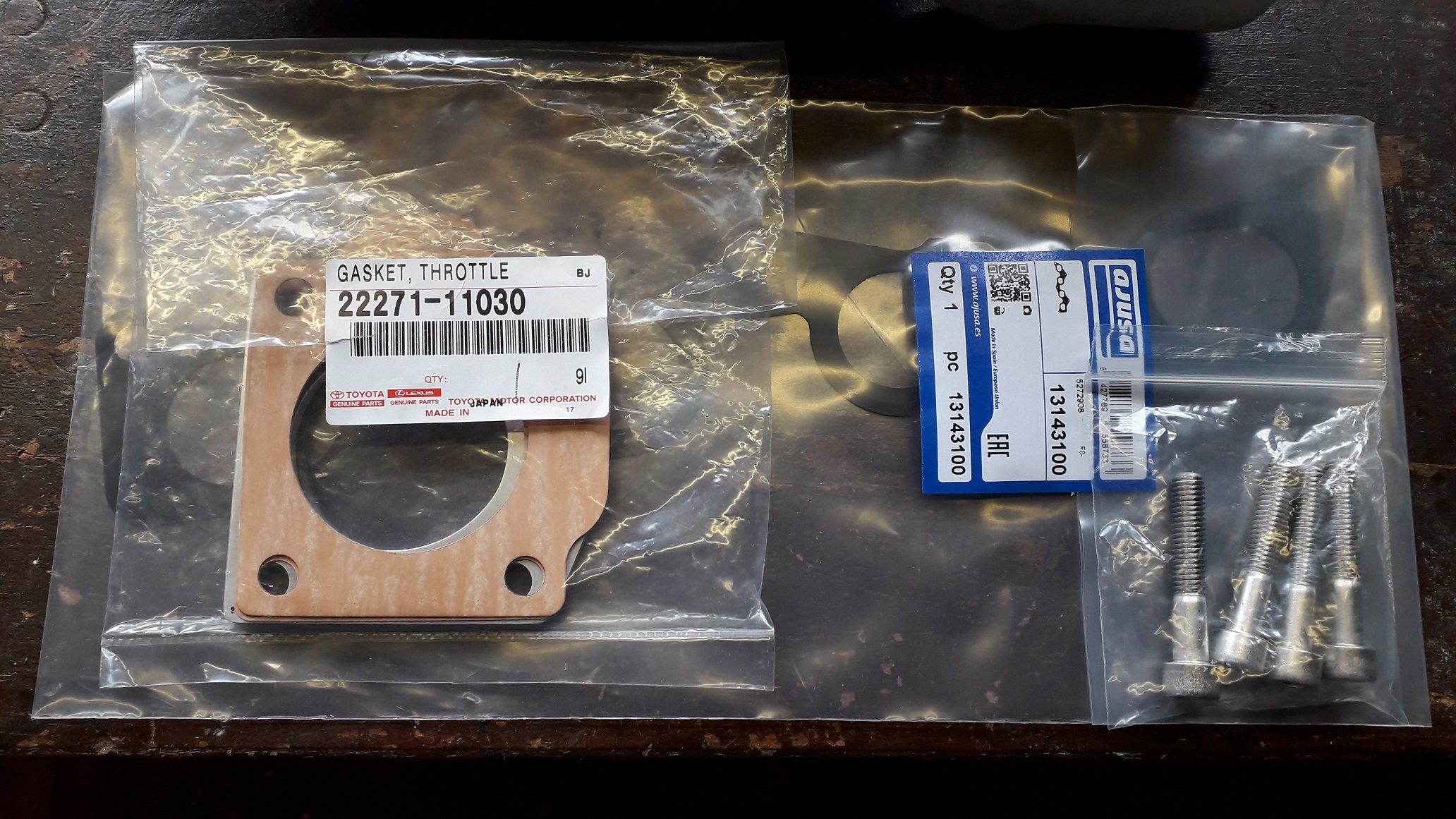
Time to fit the 4efe throttle body onto the 4efte manifold.
So with the spacer plate, 2 x gaskets and some longer screws and washers (m 8 x 45 socket cap heads) I set the throttle body up like this prior to install:

Loosely assembled the bolts to the mani and then aligned the gasket / spacer combo as centrally as possible to the TB and mani before nipping the screws up. Finally I tightened them to 19Nm.
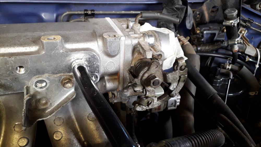
Had to move the throttle cable bracket back as the inlet manifold is shorter. This makes the TB too close even if you use all the threaded adjustment in the stock fte position.

Currently "one holing it" 😕, but will be making a brace of sorts to prevent any pivoting / flex when on the full throttle stop.

Also attached the loom earths to one of the fixing positions on the back of the manifold where the IACV transfer tube is usually mounted.
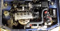
Starting to look a bit more like an engine again.
-
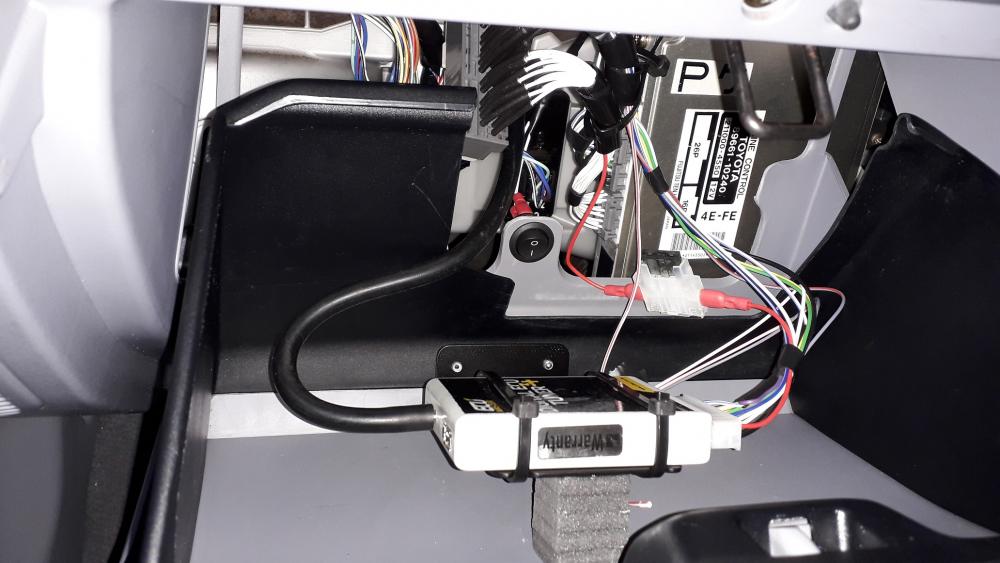
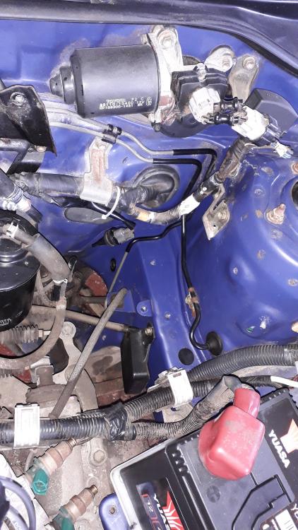
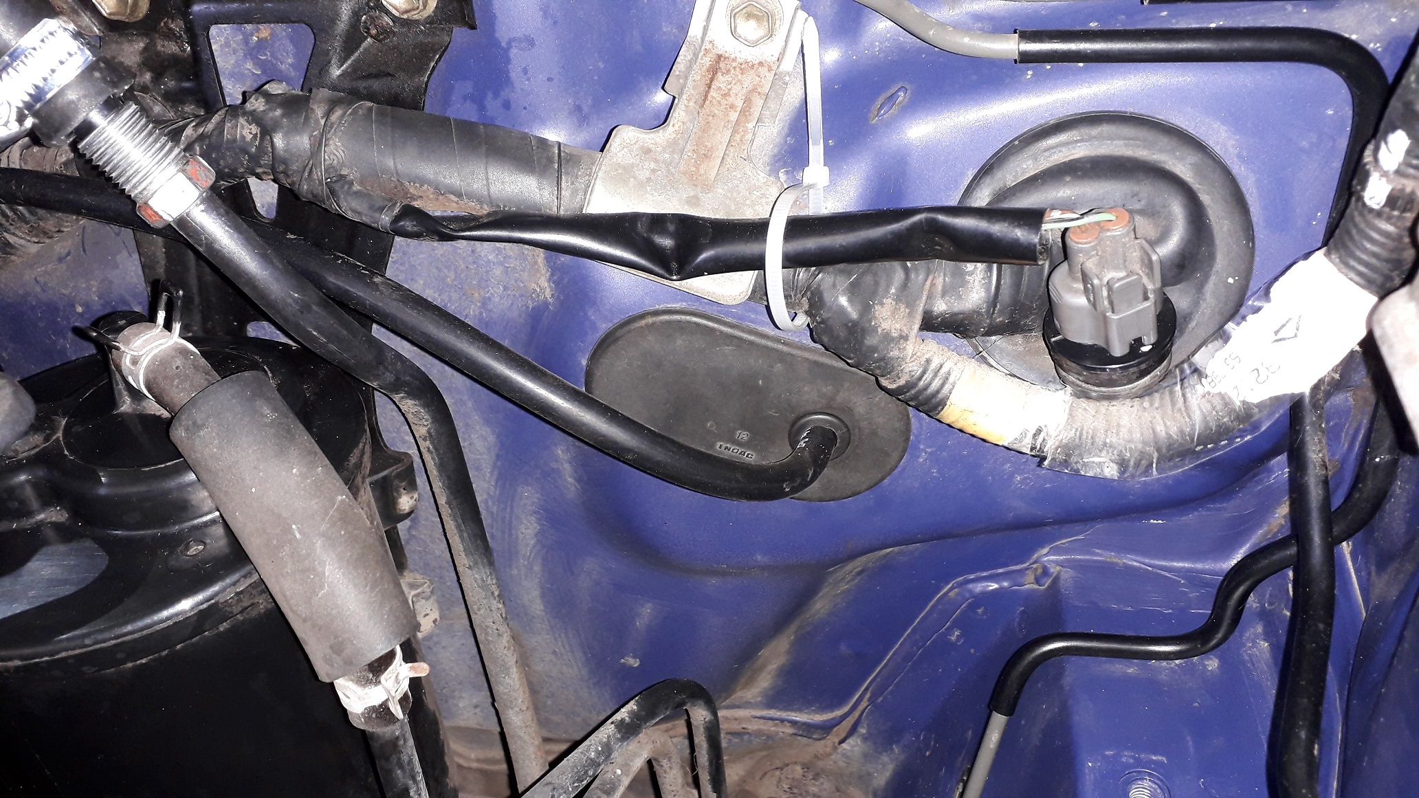
Plumbed in the vacuum / boost reference hose for the Det 3+.
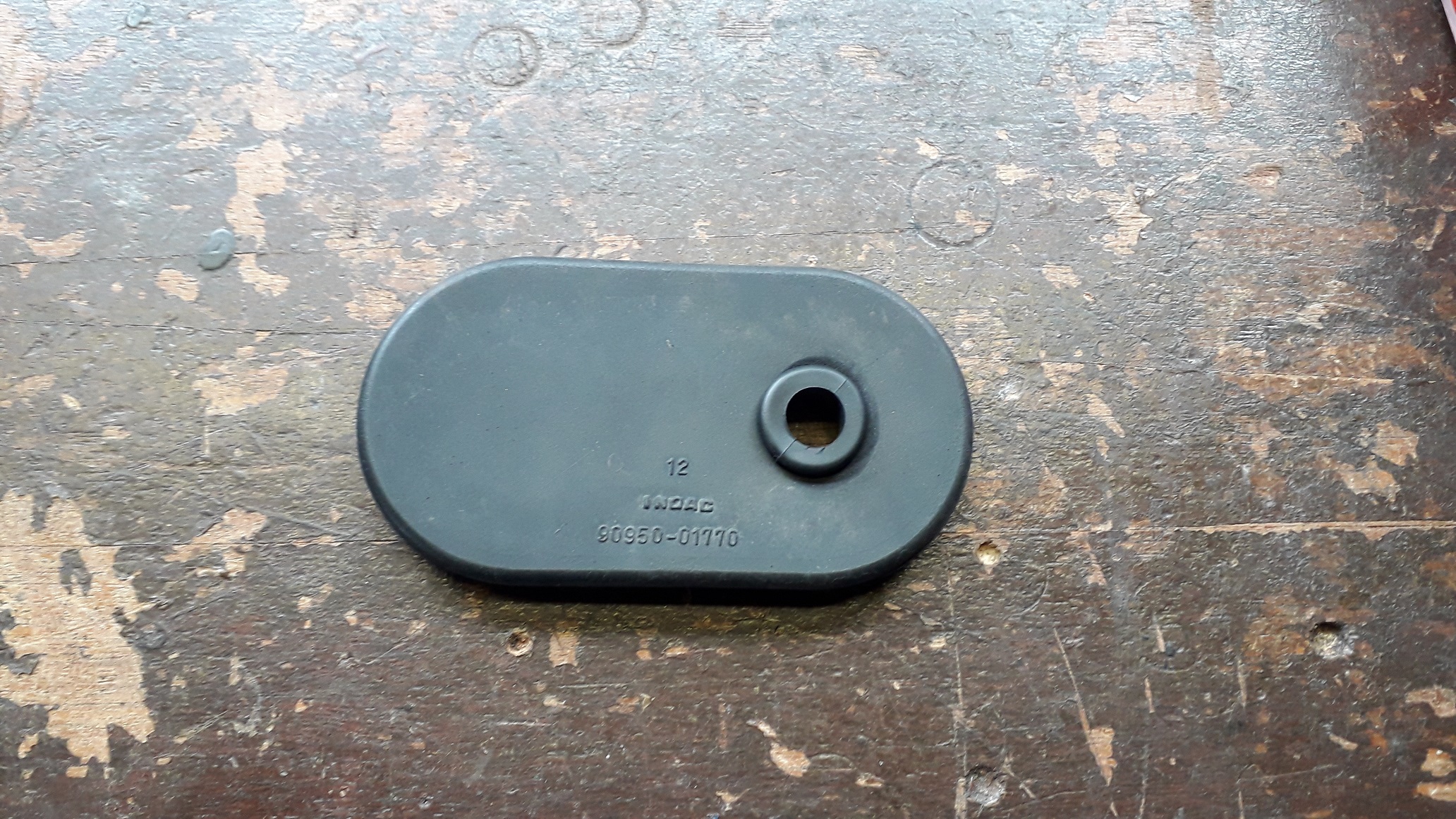
Pretty simple stuff really, started by removing the A/C grommet from the firewall and behind this I found the blanking piece in the sound deadening still in place which I removed.
Added a small grommet to the large grommet
 (bit more support to prevent kinking). Cut the hole with scissors as the step drill was not particularly effective against rubber.

Ran a 1.2m ish length of 4mm silicone vac hose from the barb fitting I installed in the manifold a while back and set the grommet(s) back in place.

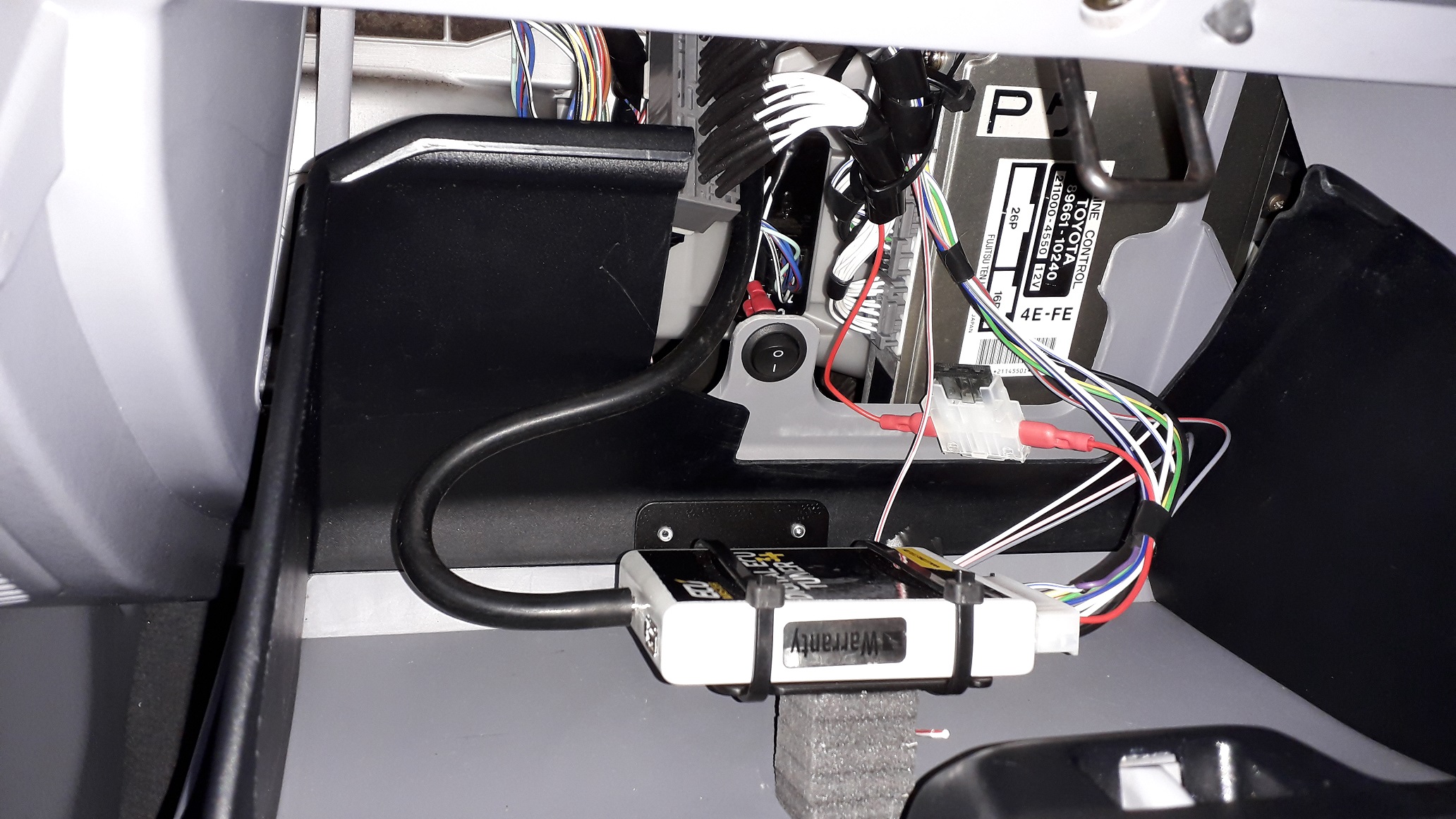
Attached it to the det 3 + MAP sensor fitting with gentle bends and enough slack to open and close the glovebox easily.
-
On 3/21/2021 at 12:07 AM, Pikey009 said:
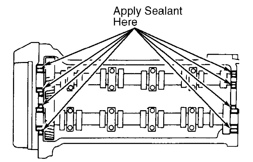
Great info with the rocker sealant as I should be getting my cover back from RWD this week and wondered where I need to apply the sealant. What sealant did you use?
Thanks mate, I used Elring Dirko again. I've been using it for the water pump also. It says it's good for water, oil and coolant etc.
On 3/21/2021 at 12:09 AM, Pikey009 said:Also, when I removed my rocker the head had sealant all the way over the humps so I’m not sure if I need to do the same when refitting
I've checked some more pictures I took of the disassembly and my cam cover didn't have any sealant on the top of the humps it was mainly on the join between hump and flat. There was some sealant a small way up the hump but not more than 10mm and only in 2 places. I think the picture shows "some sealant on the join area a bit up the hump and a bit on the flat also" which is what I had originally and how I sealed it this time.
-
Looking good mate
-
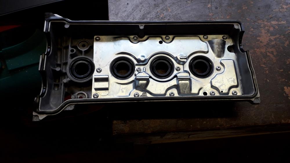
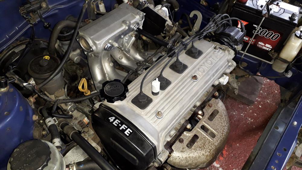
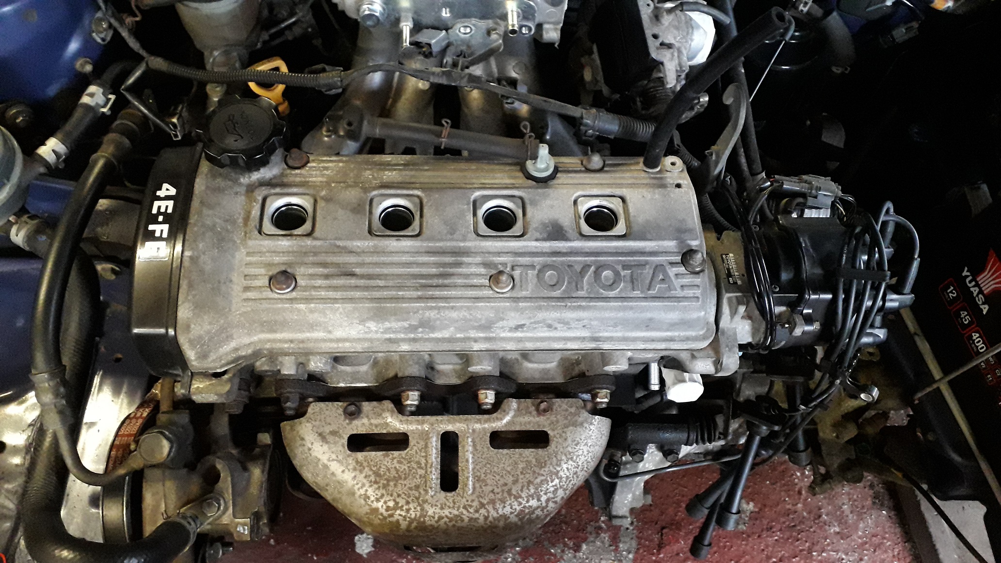
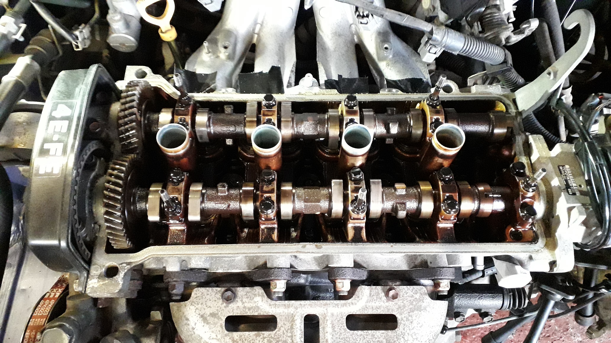
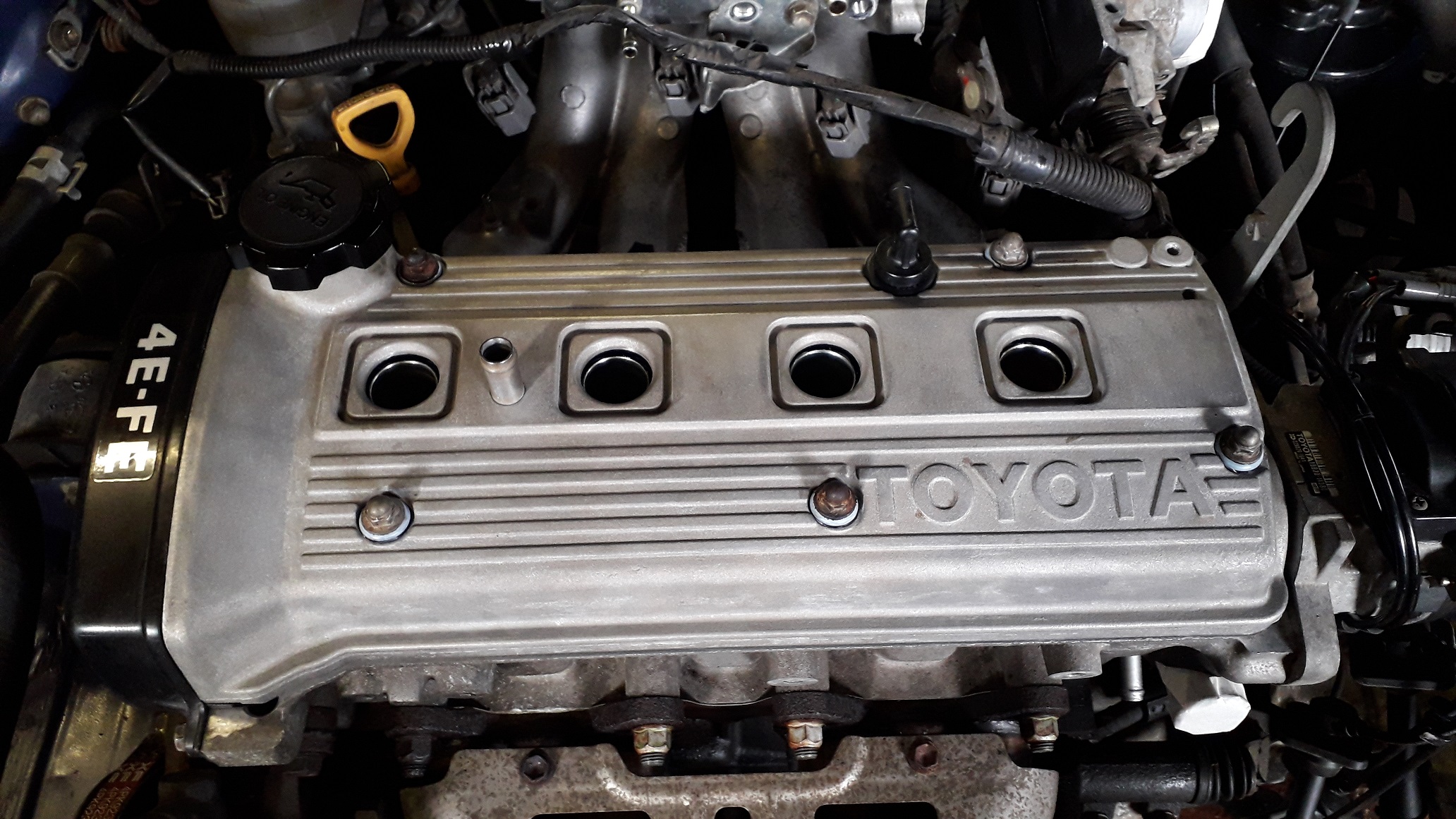
4efte cam cover install:
With the intake manifold installed it was time to change the cam cover. I first removed the HT leads and the holder that is bolted to the cover (10mm socket). Removed the 5 x nuts and seal washers from the studs. Carefully pried the cover up with a large flat blade screwdriver at the correct points. (see below).

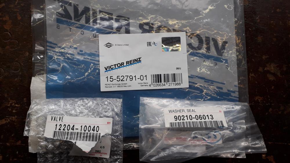
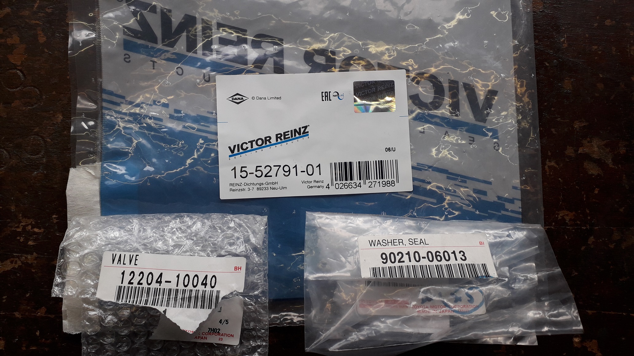
Prepped the new cover with a replacement outer gasket from the kit I got, lubed up the internal surface of the spark plug holes with grease. Installed a fresh PCV into the new grommet I installed at rebuild time. The pry points to remove can be seen as the 4 x pads outside the gasket.
Gasket set, pcv and washer / seal part numbers.
So with the old cover off it became clear that Nanza has not been serviced as often as I would have hoped! Not too bad, but still more Varnish and a bit of sludge on the old cam cover tells the story. I'll keep up with more regular oil changes and let the detergents in the oil do the work. Cleaned up the mating surface of the head including removing the old sealant from the required areas.

I applied a small bead of sealant to the areas detailed below, its basically on the joins of the plastic cam blanking plug and wherever a "hump" meets a "flat" on the sealing surface.
Cover lined up with the studs, lowered it down until the spark plug tubes prevented any further progress, tried pressing it more but the plug tube seals just stretched up further. In the end I had to help the seals over the tubes with a small blunt screwdriver. Slid down, washer seals and nuts on, I tightened them to 7Nm.

Gave the seals a bit more help to sit at the correct height evenly all round.
HT leads / block back on, plumbed in the PCV and blocked the other cam cover breather pipe temporarily with a piece of tube and tape. Cut the 90 degree bend off the original 4efe brake servo hose and it installed straight to the 4efte manifold fitting. Also got the MAP sensor plumbed in with the necessary longer vac hose.
-
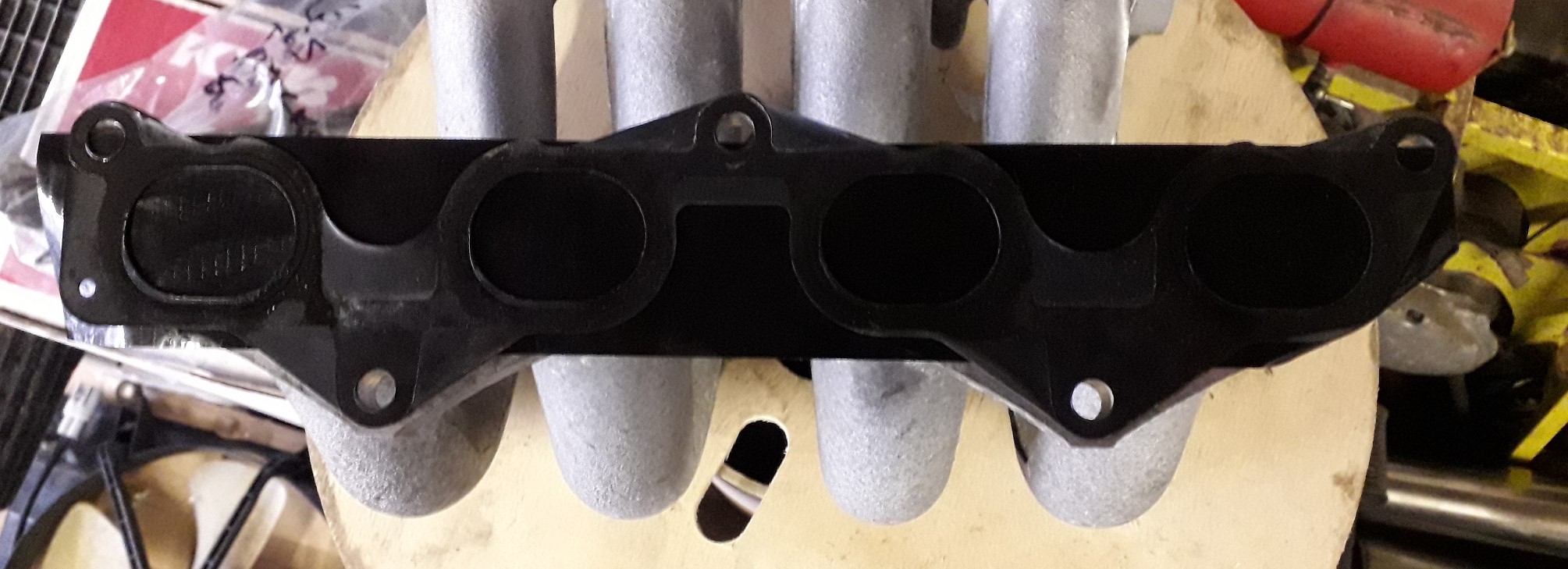
4efte inlet manifold fitment:
Cleaned the mating surfaces of the mani and head, noticed the mani had some light scratches to a small area of the face which should be sealed by the gasket, if not I will add some sealant to the area also.
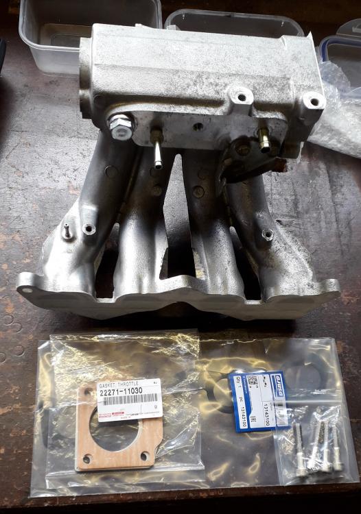
Used a new Ajusa gasket to the head as well (Part number 13143100). Also got the gaskets and spacer ready for the throttle body install, unfortunately the bolts I received were too short so I have had to return them for some longer items.

The gasket can only be fitted one way round or the mounting holes won't line up, it needs the square section with the small hole on the drivers side. Not to be confused with the different gasket that has a square water channel area for the 5e and early 4efte heads on the passenger side. Can't get it wrong anyway.

Bolted in place with the original 3 x nuts and 2 x bolts, I tightened it evenly to 19Nm (12mm socket). Less fiddly to install as the runners are so short improving access. Unfortunately the lower 4efte brace won't fit from the mani to block as it interferes with the water pump pipe. I checked the pipe part numbers and they are different from fe to fte. I do have the upper brace to go to the head however.
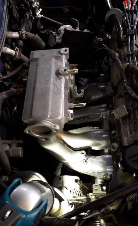
Also cleaned up the 24 years of mud / grime from the area behind the air filter box.
-
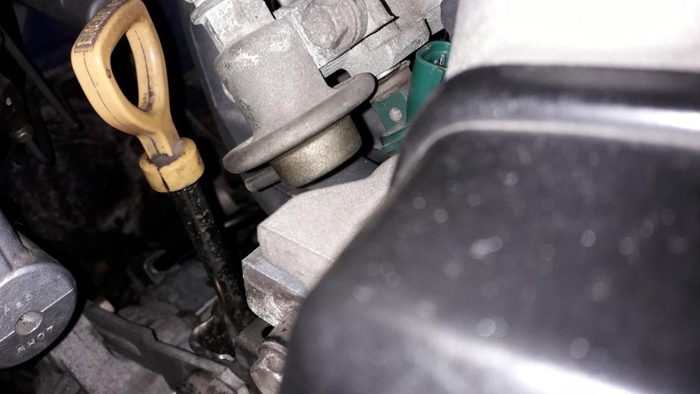
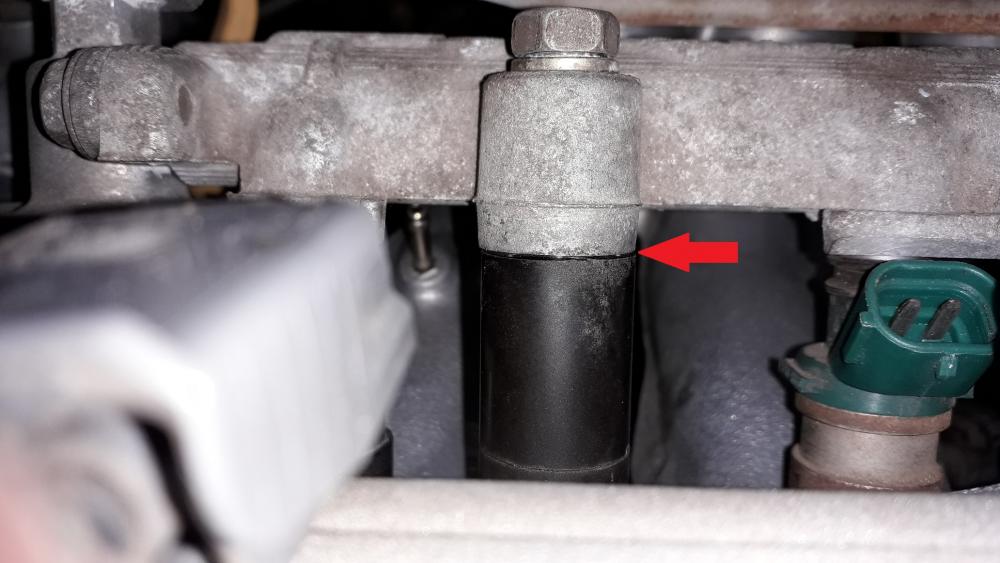
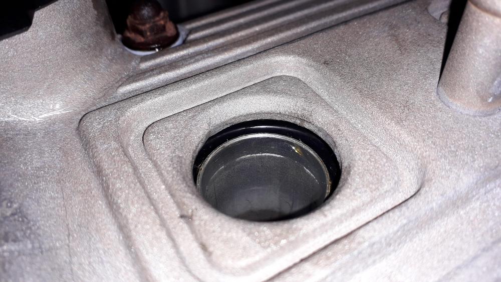
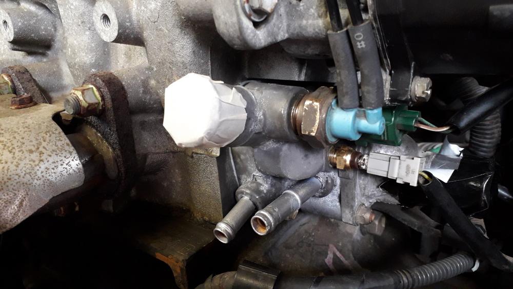
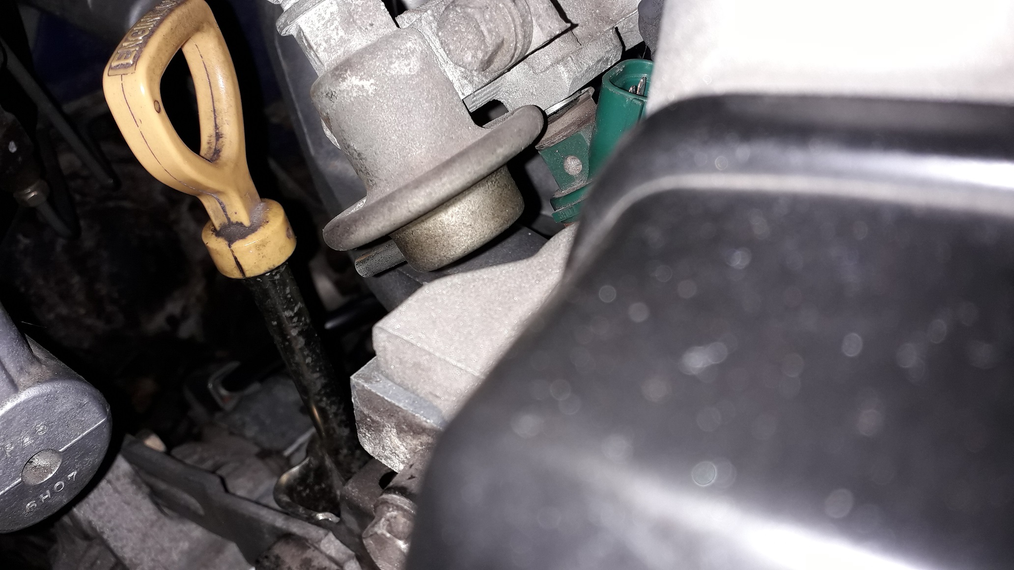
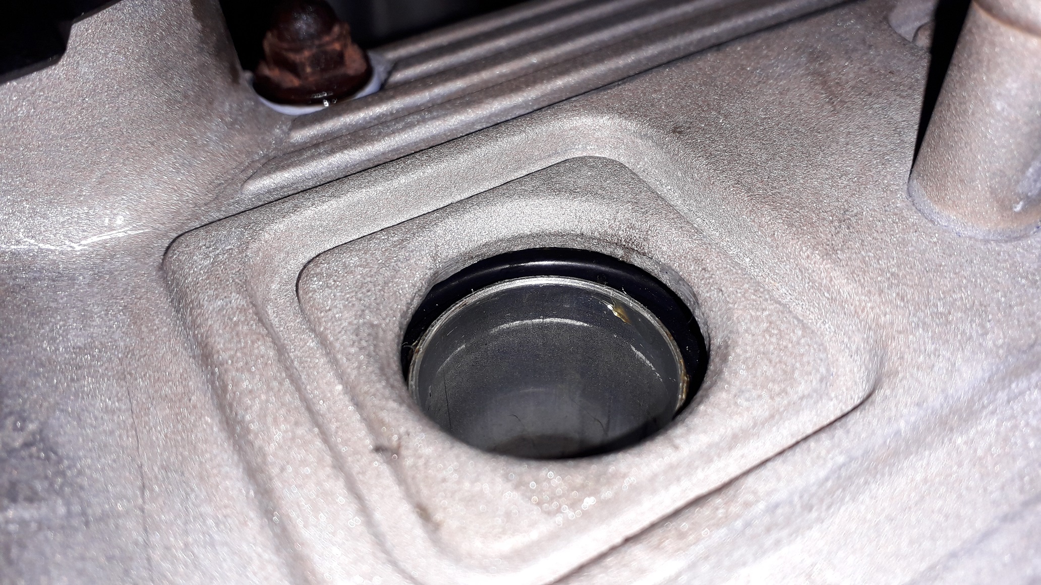
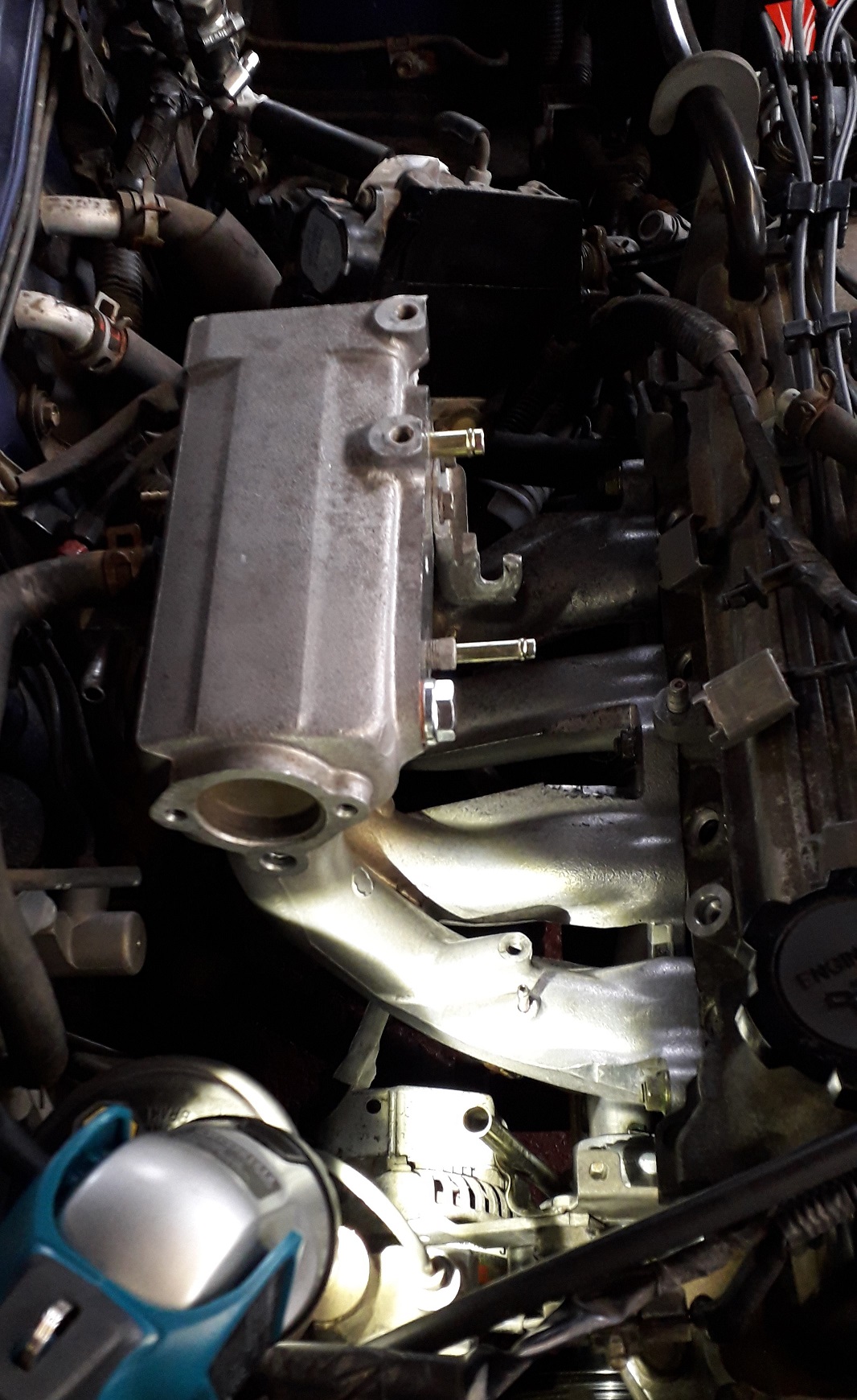
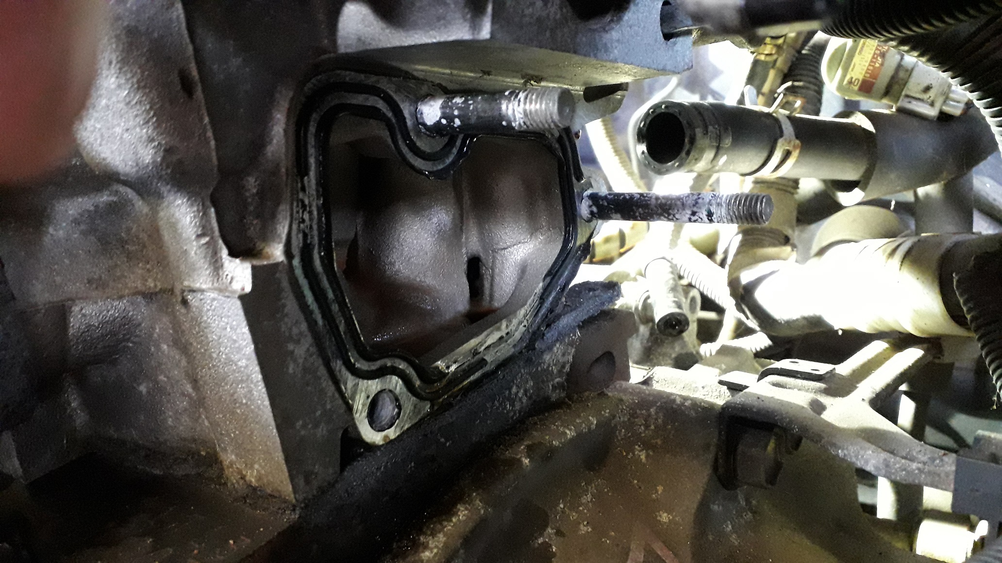
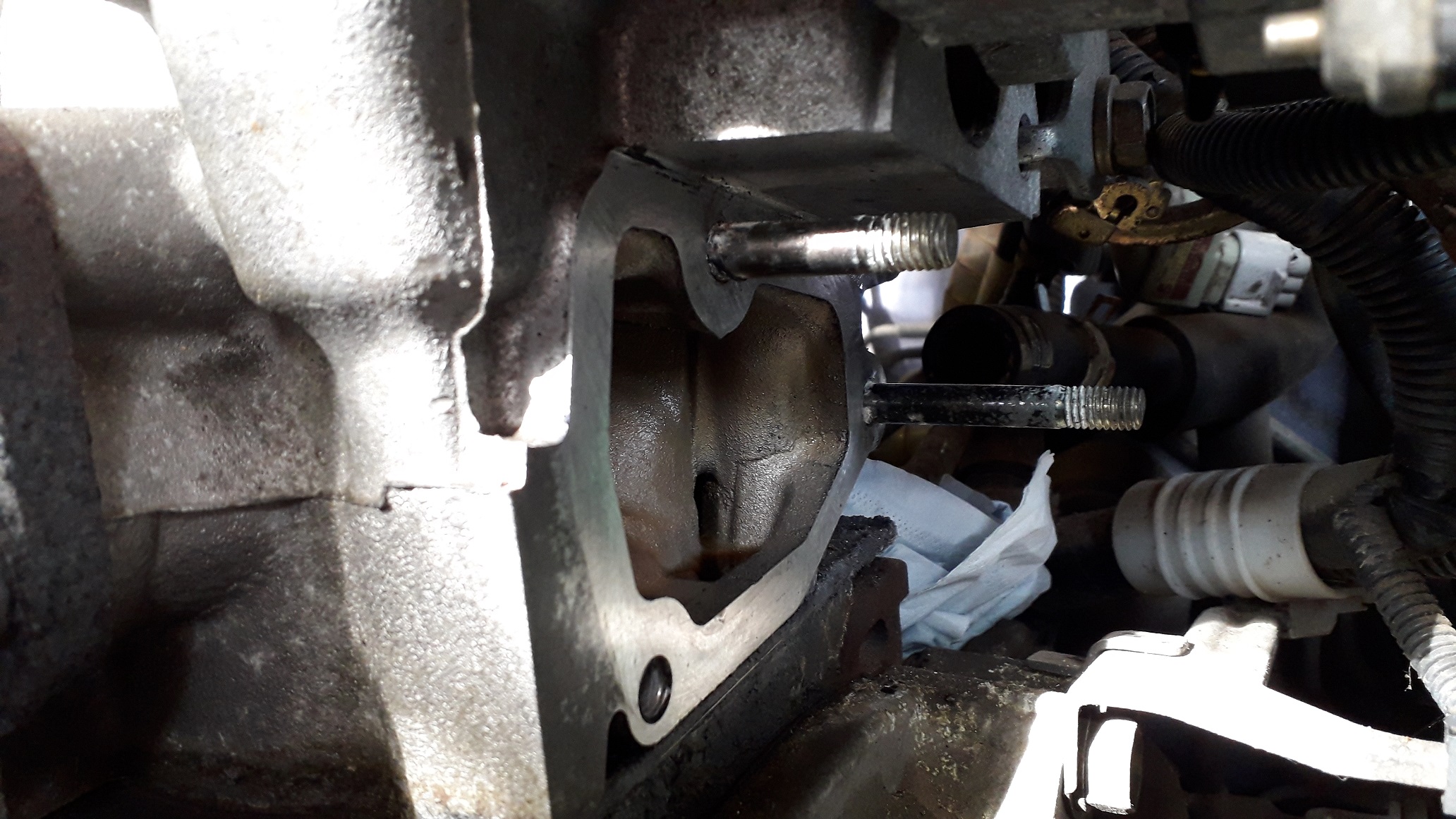
Removed the existing 4efe housing after disconnecting the IACV and heater hose, was left with the sealant to clean off again, Stanley blade very carefully as I was working with an Alu surface this time.


Now the rear hose to the water pump pipe was out of the way I could re-insert the pipe. I added a new O-ring to the pipe end and lubed it up with car shampoo. Aligned the end with the pump and pushed the pipe in straight, up to the stop. Bolted the bracket back onto the block (10mm socket).
Re- installed the dipstick tube with a new O-ring (10mm I/D x 1.75mm cross section).

Added a layer of sealant to the groove on the rear of the housing and some to the flat areas either side, hooked the rear hose around the back of the block and lined up the housing on the 2 studs in the head. The TVV valve ports were interfering with the distributor (hence the 9'oclock preferred position in hind sight.) and as the dizzy position was already marked I loosened it off and rotated it out of the way. Lined up the rear hose with the water pump pipe and then slid the housing home, pressing it to the head to create the seal and tightened the fasteners evenly to a torque of 18Nm. Readjusted and tightened the dizzy. Re-attached the electrical connectors and will re-attach the other 2 hoses when the sealant has cured.
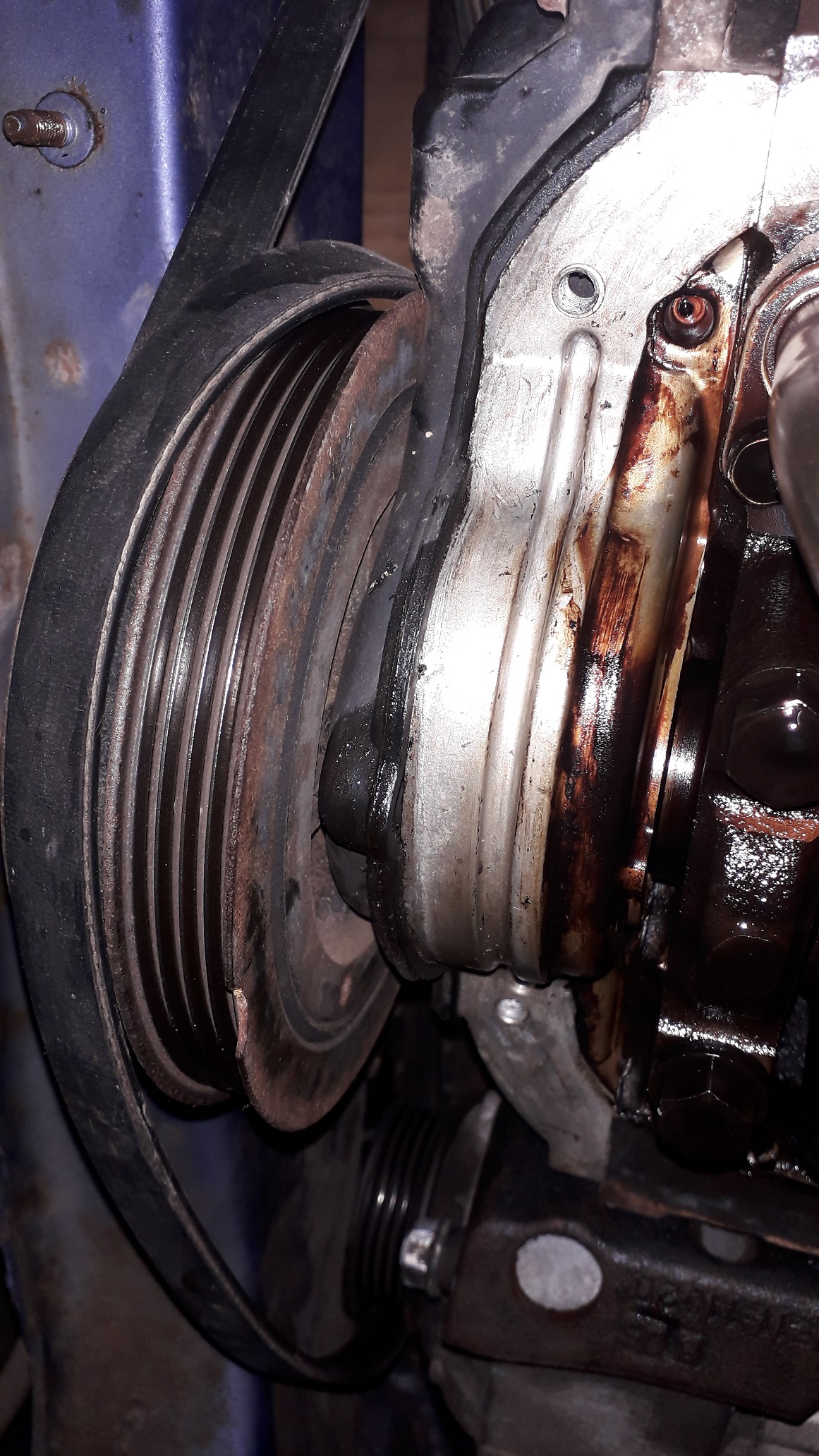
Not really any need to show the alternator re-install. Drained the engine oil / coolant also.
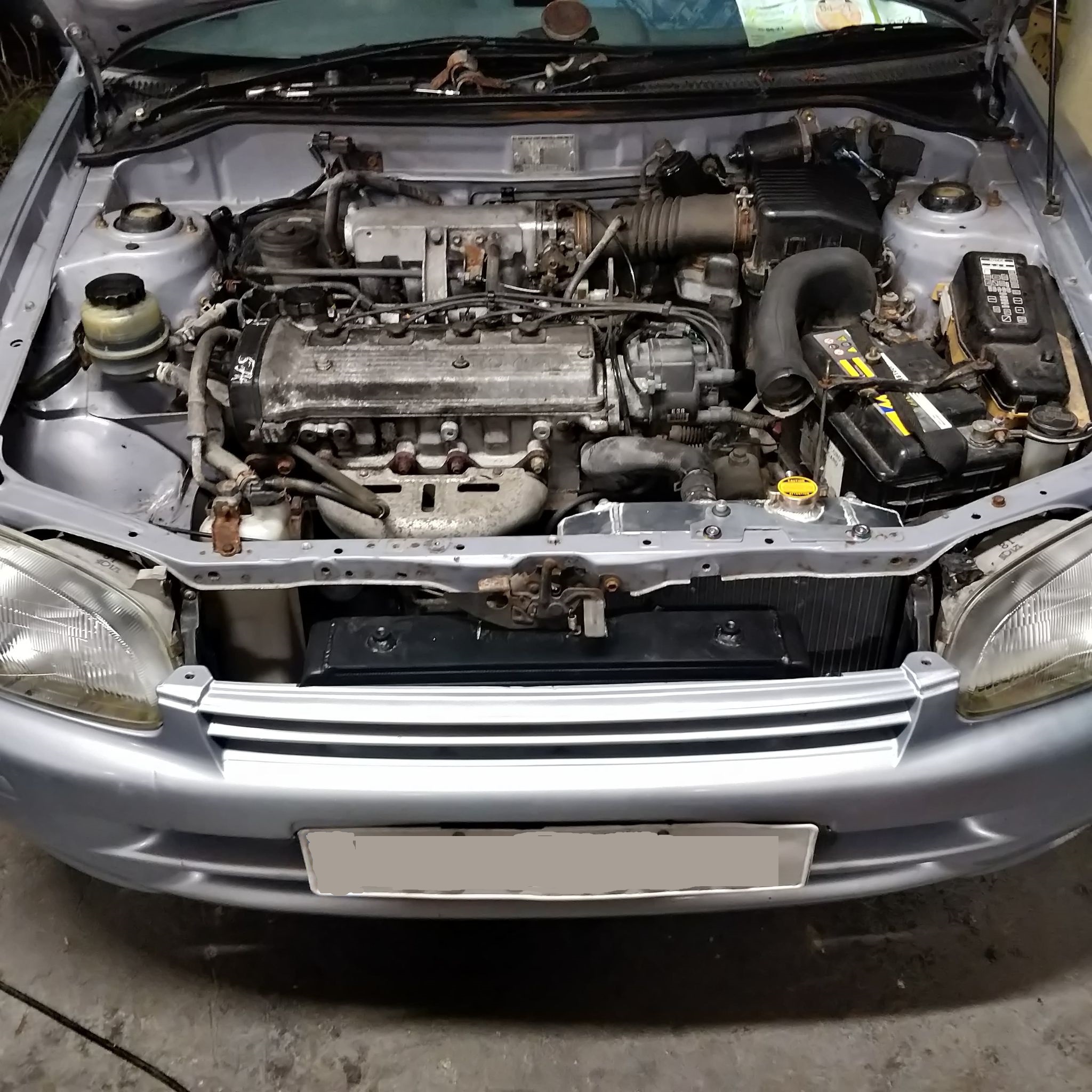


Claymore's sleeper 4efe+t-t+t build (R.I.P. the Nanza)
in EP91 Progress Blogs
Posted · Edited by Claymore
The exhaust saga continues.......
The gravity decat downpipe I bought was always questionable from day 1.
Lower holes to mount to centre section were a week out!:
After some rage filing:
Fitted to the turbo with a new Toyota gasket (part number: 17279-11010)
When mounted to the turbo, the lower flange was clearly welded to the downpipe twisted anti-clockwise slightly and the top right hand corner was tilted closer to the front of the car.
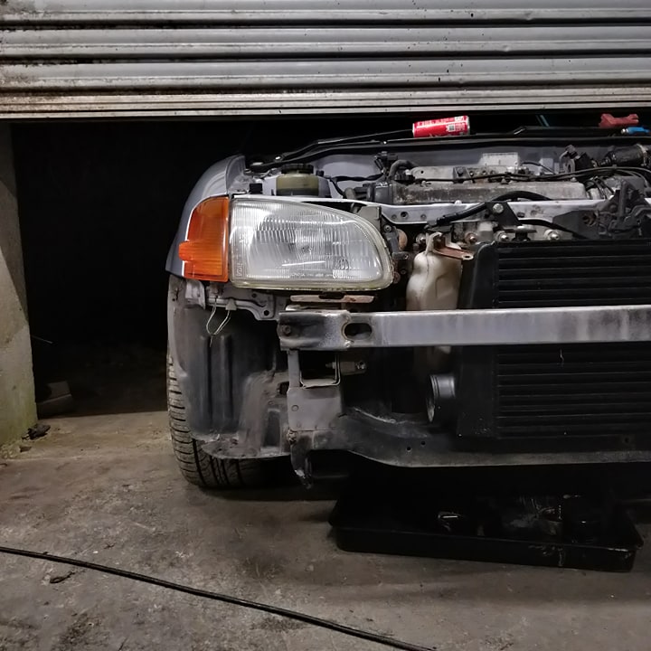
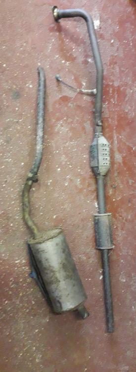
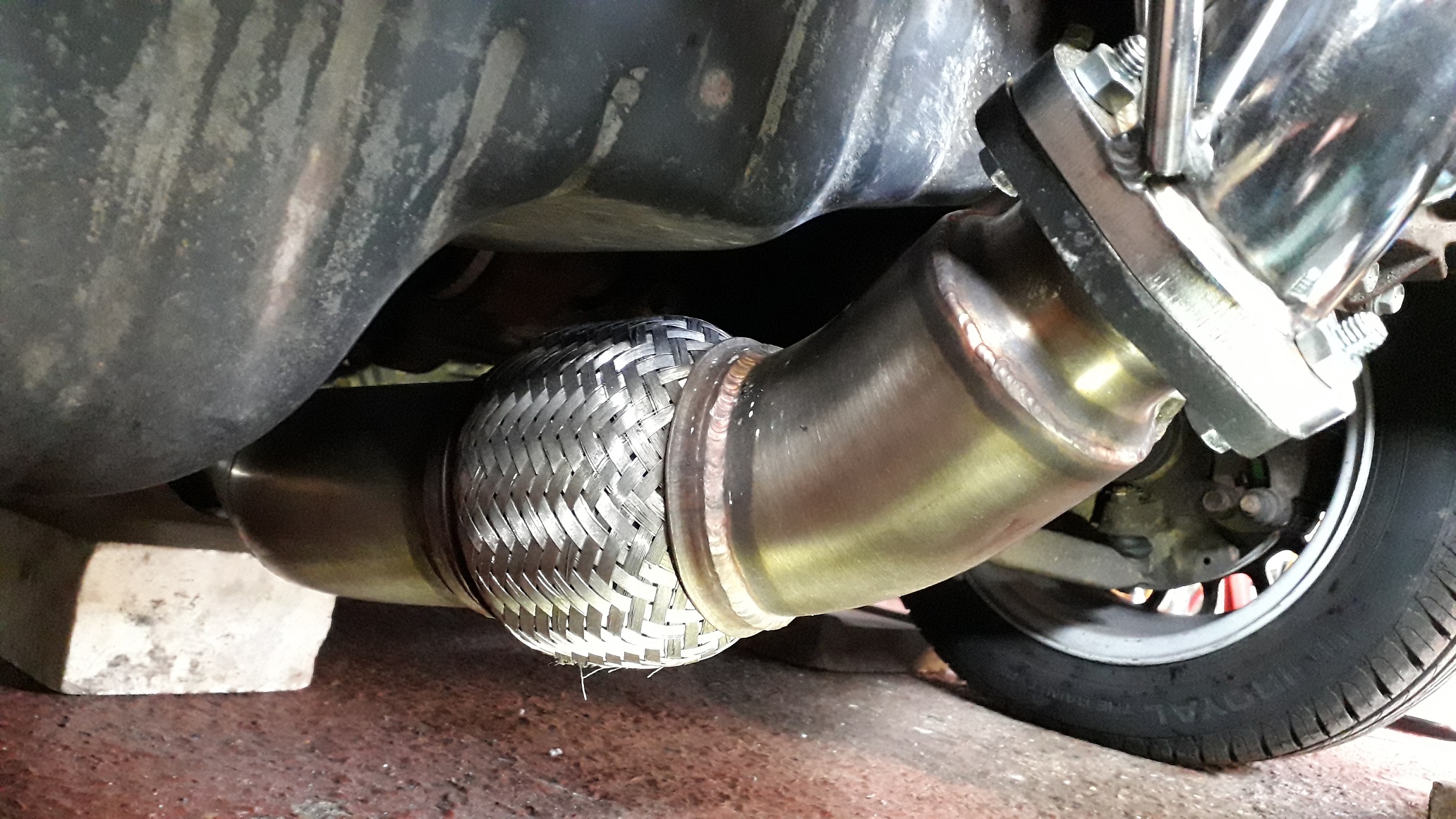
Built up the TD centre exhaust section, and fed the back box over the rear beam / panhard rod support and joined them up under the car.
Lifted the centre into place and it was approx. 25mm short of the decat so once pulled into place it was obviously sitting off to the passenger side. I rotated the exhaust in different positions also at the decat flange and the fit improved slightly but still not good. Spent 4 hours on it at the weekend trying different solutions, but the decat angles the first part of the centre exhaust off towards the passenger rear wheel and it cant be re aligned. Also shows the difference in rubber mount positions between 4efe and Glanza.
So the decat has to go as I believe all the alignment issues stem from its poor manufacture.
I've ordered a TD decat downpipe which should arrive today.
Also retrieved the stock O2 sensor bung from the original exhaust, Cleaned up and linished the curved underside to fit the 3" TD system.
Ordered a few bits for the radiator (fan, hoses, clamps) and am waiting for their arrival also, seems a lot of delays and companies taking orders with no stock on eBay at the moment, but with the current global situation its understandable.