

Claymore
-
Content Count
660 -
Joined
-
Last visited
Content Type
Profiles
Forums
Wiki
Media Demo
Store
Calendar
Posts posted by Claymore
-
-
16 hours ago, Frankieflowers said:
Question for you. Should I continue my build thread on this one or start a new one? Asking you because you’re the Admin.
Hi Frankie, I'm flattered but I'm not an admin of the forum.
If you ask @Rob SR or @Akayakpotter or @Socks they might be able to move this thread to the "other motors progress blogs". Or just start a new build thread and link this thread as the first post if you want.
Glad its arrived 👍
-
16 hours ago, Sam44 said:
yep water/liquid on the exchanger surface aids convection/heat transfer. also the space at the rear needs to be relatively low pressure/largish.
heat ex changers are a big part of my work.
one of the down sides is the effects on gearbox oil temp and air charge temps.
ive opted to run a lower temp thermostat as well as improve heat transfer from the piston crown threw the cylinder bores by increasing/maintaining great engine block coolant pressure. over 30 psi threw out the rpm range. 78deg thermostat off the 5efe paseo give good in cab heating. as well as improves engine power output/reduces peak engine running temps.
instead of changing the radiator.
Never believed in low temp. thermostats.
The thermostat is to help heat an engine up quickly from cold and maintains temp. at low load and cruise. As soon as it increases to high load, coolant temps. increase rapidly to 100+ deg C and the thermo is wide open, having no effect at temperature regulation as the coolant flows freely to the radiator. The radiator is responsible for cooling the engine at high load and not the thermostat, it might as well not be there.
Also the engineers at the factory designed and manufactured the engines to specific tolerances to run at the original operating temperature and changing this may affect the clearances and wear on some engines, not such a problem on a dedicated track car but as a daily driver you would be spending more time running with the engine at the new, lower operating temps. Coolant temp. is also related to ECU fuelling so may adversely affect that also.
The cooler the cylinder walls of an engine become the greater the thermal offset to the combustion process meaning they are better at absorbing heat from the combustion (quenching effect) and as we know, combustion heat = power. Obviously it is a balancing act of the correct amount of heat in the correct components of the engine, cool enough to resist detonation and keep the piston temps. acceptable with the head hot enough to vaporise the required fuel etc. blah blah.......
Personally I would look into more efficient or larger radiators but its your build. I did read an interesting article on it which made sense to me.
-
2 hours ago, Sam44 said:
a big thumbs up from me.
i always try and use fan shrouding these ramp up air flow threw the radiator increasing heat transfer and radiator performance quite a lot.
another area to look at is the front sealing edges. the radiator has is a natural air flow restriction this leads to air flowing around the edges (air spillage), this can reduce heat exchange performance massively.
Its quite an interesting subject and I learned some interesting stuff whilst researching the intercooler setup from corky bell and the Jeff Hartman books. They're just heat exchangers after all.
The current fan I'm using is straight blade (better), it is ducted (has an outer ring to draw air through rather than in at the sides) and sits as close to the radiator as possible. It's deffo more effective than the Toyota model it replaced as it runs for less time to cool the coolant the same amount the O.E. fan did.
The bonus of the shorter rad width is that a fan now covers more of the core. Where as before the wider radiator only had approx. half covered by the fan and made the shroud all the more important. The downsides of adding a full size fan shroud to the radiator are obviously the added weight and extra depth (needs to be mounted with an air gap to the core) in a crowded engine bay.
The downsides of the thicker core are: the thicker a core gets the more resistant to airflow through them they are (assuming no other changes to fin density etc). Also the second half of a cores thickness only does about 25% of the work. Stands to reason really because the air flowing through absorbs heat and the further through the core it travels the hotter it gets, the closer in temp. the air gets to the object it's cooling the worse it is at absorbing heat.
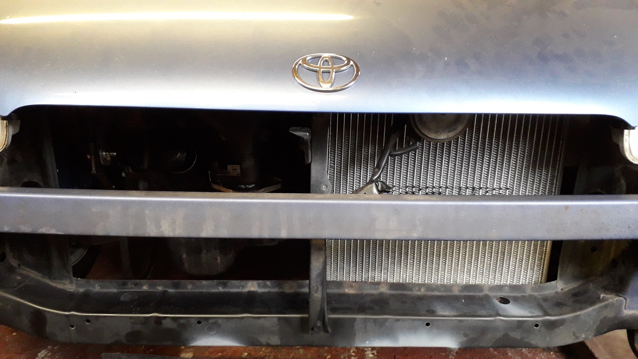
It's deffo an improvement if you can duct air into a heat exchanger rather than letting the air hit the face and (taking the path of least resistance) spill round the sides. A vertical wall down the centre of the bay opening reaching from rad to bumper would improve the air direction into the rad, the other 3 sides are currently ok and offer some form of ducting / help and therefore less gain to be had.
Other issues arise from obstructions i.e. bumpers, oil coolers, intercoolers etc. all are necessary components but their location and design can also play havoc with trying to cool an engine. It often ends up with pre-heated air from other heat exchangers being fed to the radiator reducing its efficiency where as a more suitably sized intercooler (or a different shape) and a relocated oil cooler matrix would leave at least 50% rad core receiving road draft air.
It's a fascinating subject and I really did enjoy researching it. I've only scratched the surface (and typed up hardly any of it here) but there is some great info out there and well worth a read.
-
Sounds good, you have a very interesting build.
-
3 hours ago, Androo26 said:
Its been a long time , but ive got some further information to share.
Since the last post Ive built a forged 1.3L 4E and still have the 4cm Turbine TD04L on board. This has made a best of 160.0 Kw at the wheels on 19 psi.
Super fun to drive and traction is a problem even with a Quaife LSD.
Long story short is im getting a bit more serious about lap times and also improving the efficiency of the turbo setup.
So i decided to measure the turbine back pressure vs intake manifold pressure.
Turns out its a bit high for my liking. 1.9:1 . Id much rather it around the 1.5:1 or less.
Im going to get the original 6cm housing Ceramic coated and then swap it over essentially making it a stock TD04L again.
I will re take the turbine back pressure measurement and get back to you guys with the findings.
Still very much enjoying the Starlet life here in Australia.
Nice to hear mate, is the AU starlet forum gone now? Can't seem to find it anymore.
Your build thread on there was awesome.

-
Odds and sods time
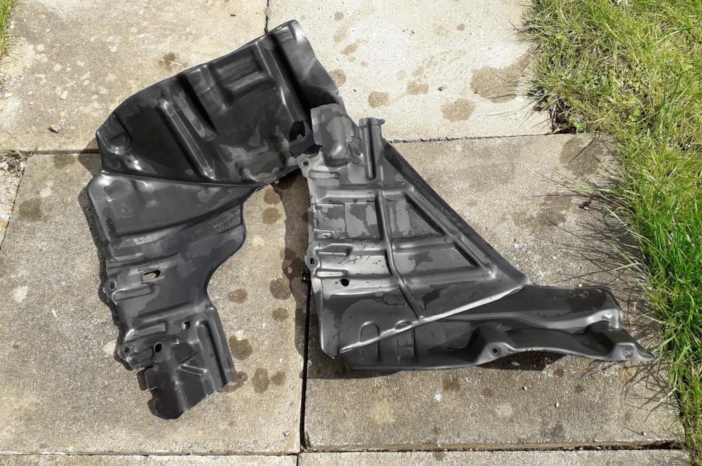
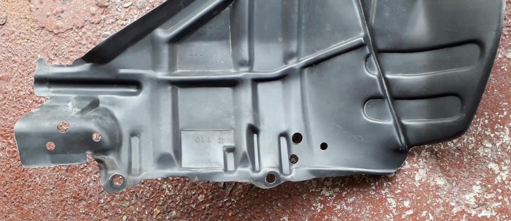
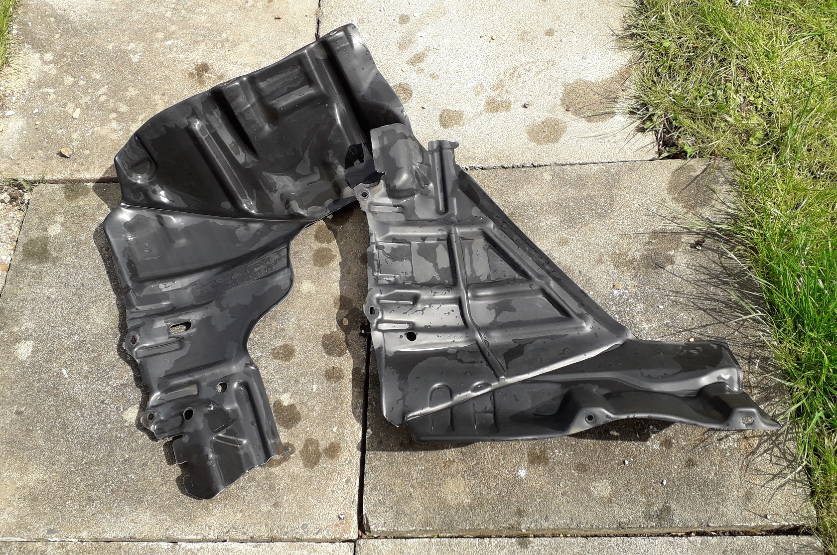
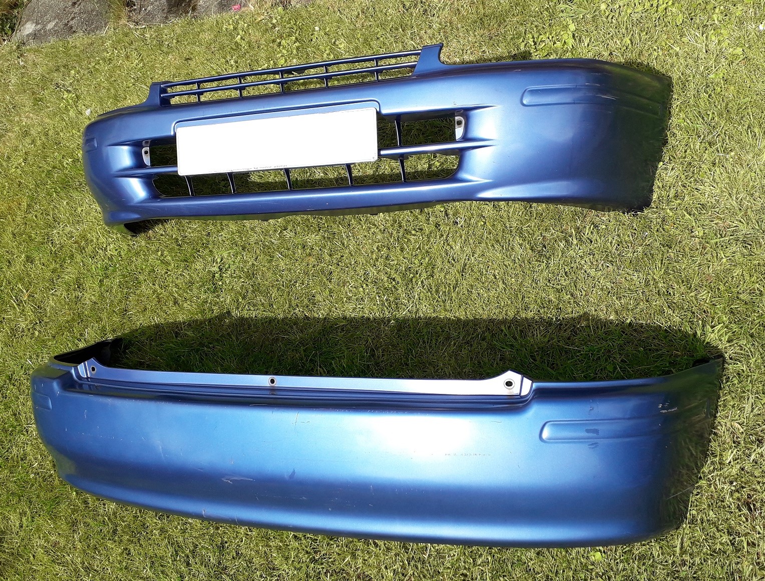
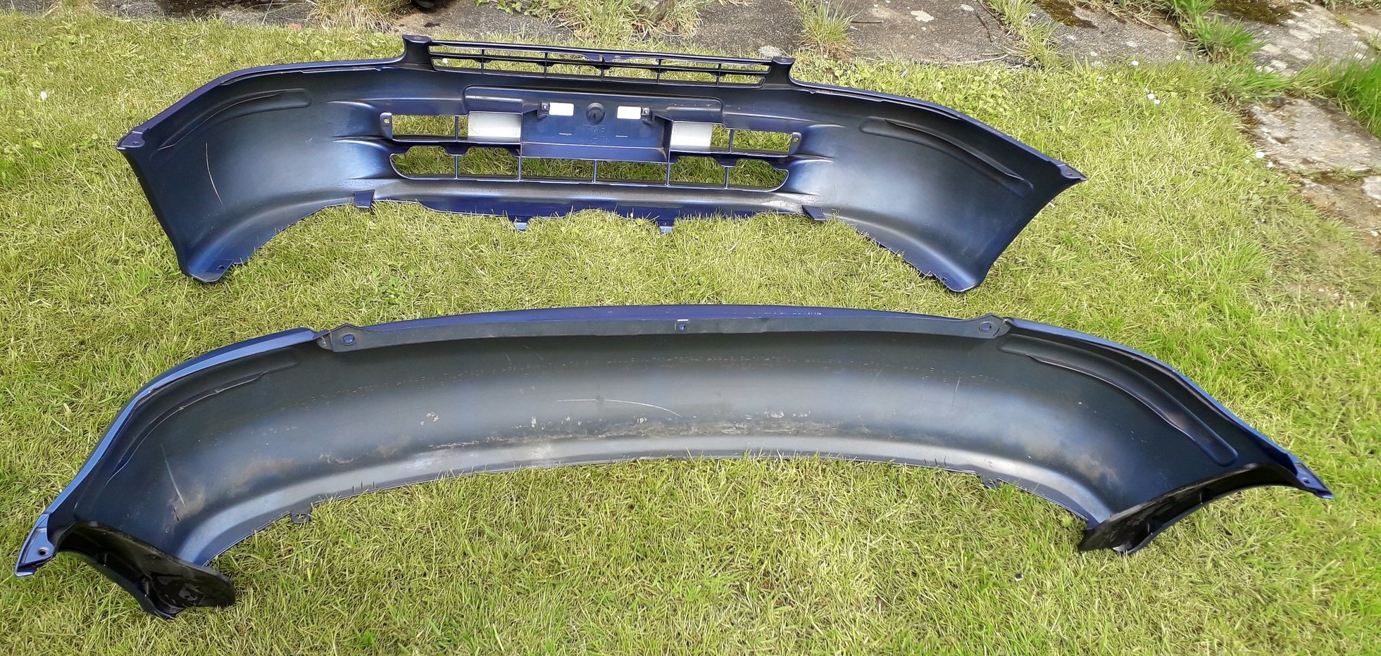
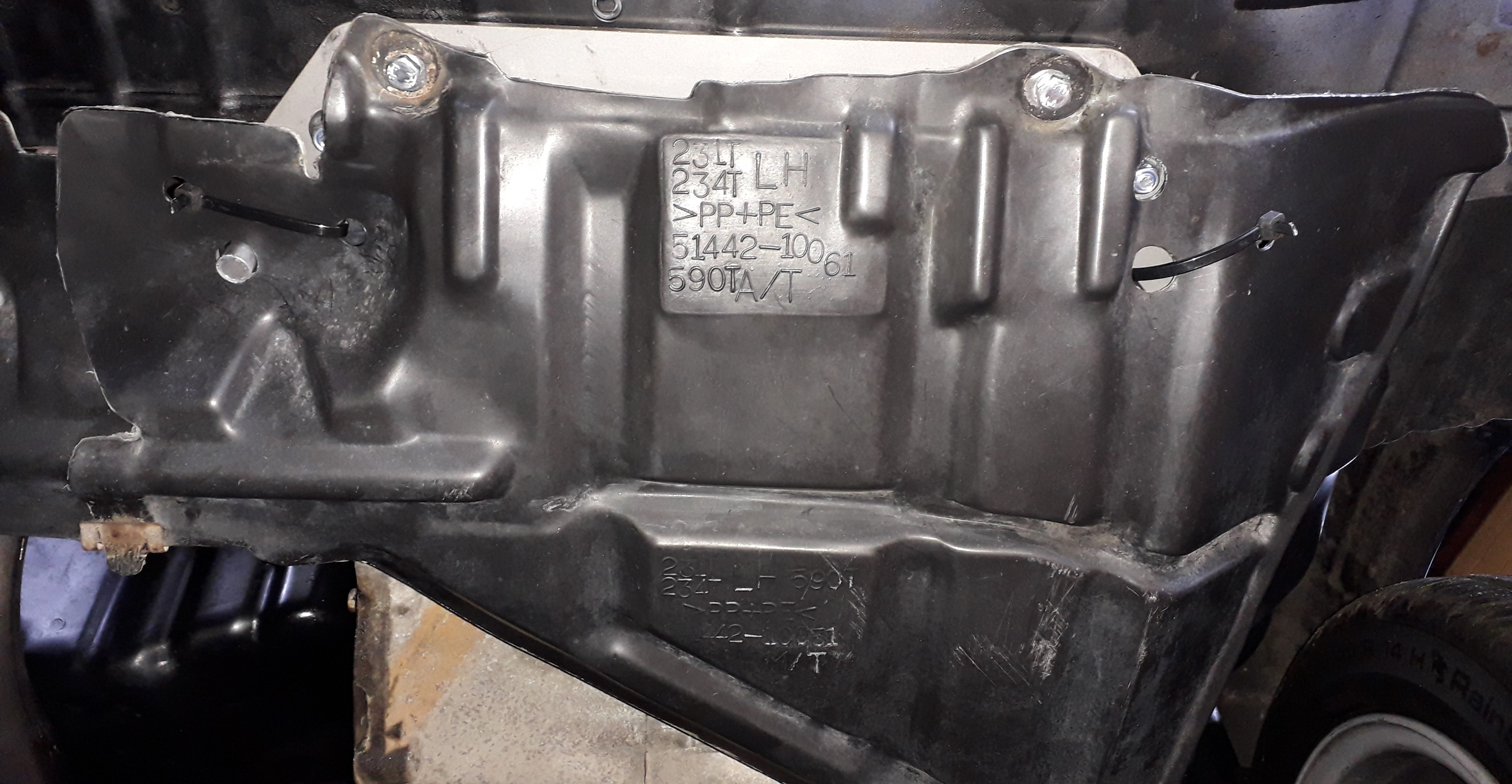
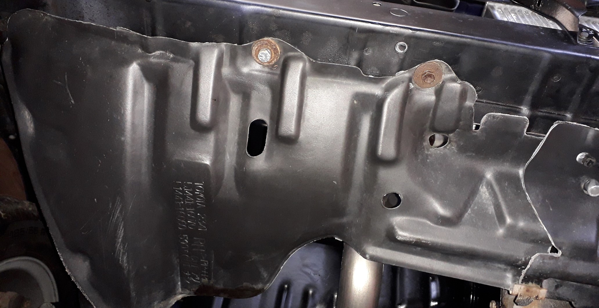
With the car now mechanically back together and in the best state / condition its been in for years it was time to finish the assembly of the bodywork. With all the bumpers and undertrays off it made sense to clean them before re assembling them to the car.
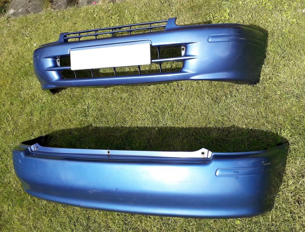
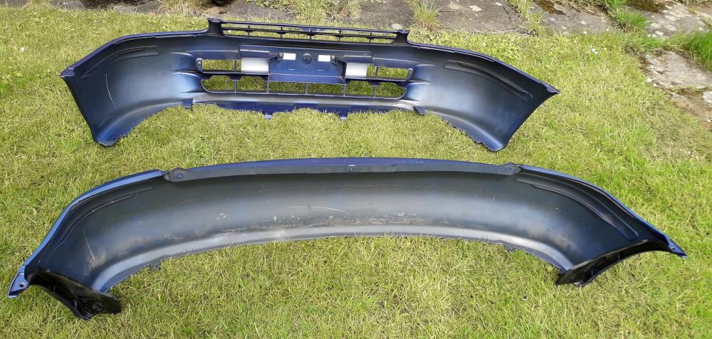
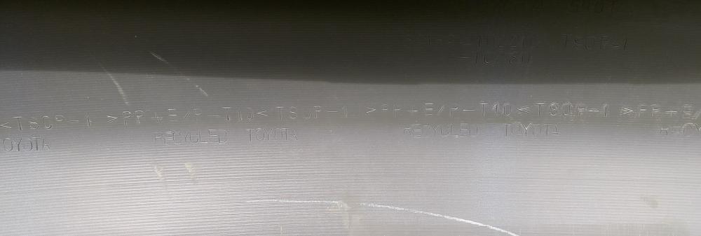
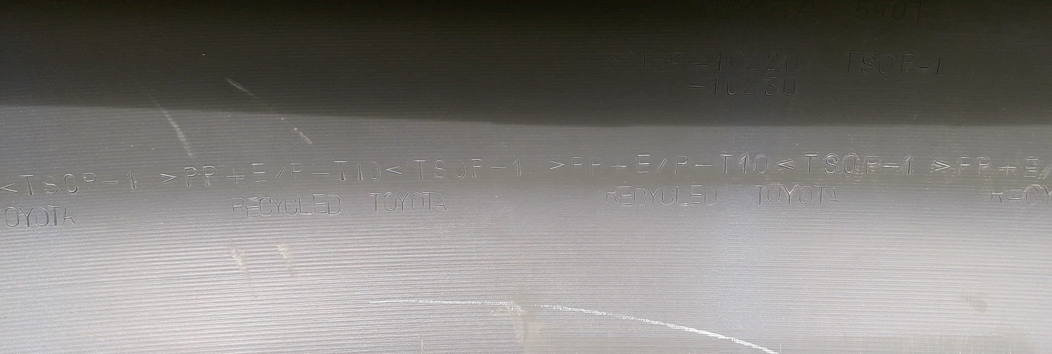
Toyota were apparently very proud of the recycled nature of the Polyprop they'd used which is why they moulded it 11000 times on the inside of the rear bumper!
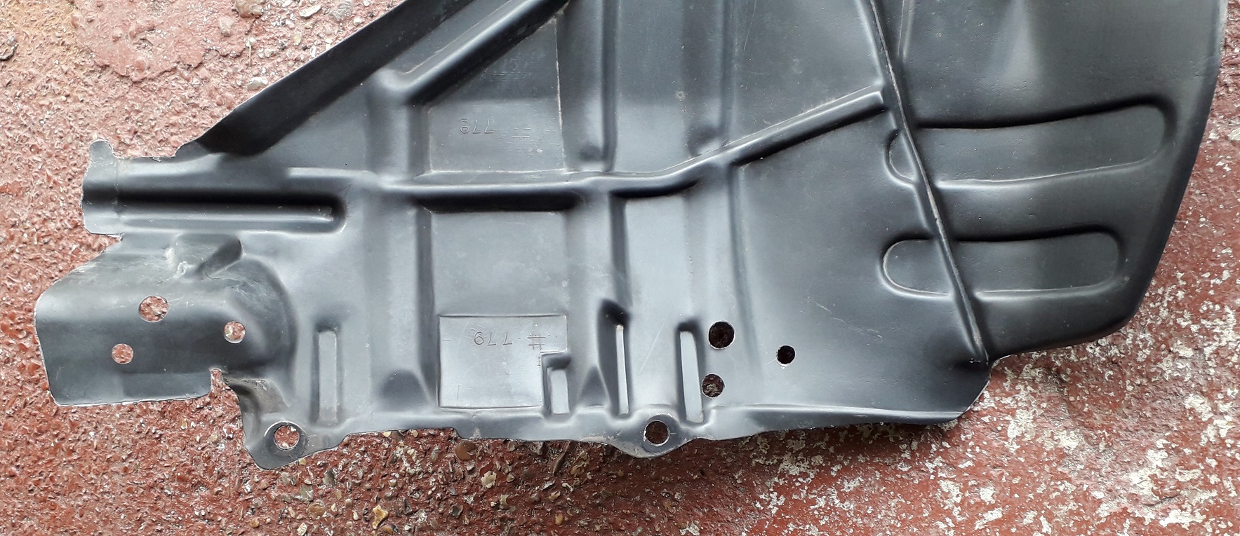
With the lower rad bracket now using the passenger side undertray mounting holes and the radiator mounting posts interfering with the tray, some drilling had to occur. Gave the wheel arch liners a clean on the "hidden" side and the front cross member / side uprights and bonnet catch vertical support got a "no prep" blow over in satin black to tidy them up.
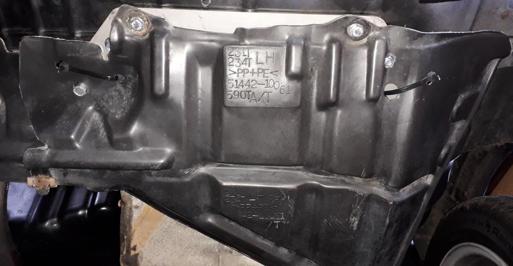
Decided to cable tie the passenger side tray onto the lower rad bracket. It is possible to bolt through it and the bracket but this introduces soft polypropylene / polyethylene into the bolted connection (basically a plastic washer) which I wasn't keen on. Also if it only uses these 2 bolts to mount when you remove the tray the rad comes with it. Side frame mountings and drivers side used original locations.

The bonnet has always rattled on the catch a bit at idle so I raised up the rubber feet on the slam panel as far as I could without buggering up the panel gap and moved the catch down a touch. Bumpers back on and rolled out into the sunshine for a bath.
-
4efe Stock exhaust replacement.
The old centre exhaust section was pretty much shot due to excessive rust. It was Toyota branded and was most likely the original system. The back box (also Toyota) was in much better shape leading me to believe that it had been replaced at some point.
So I sold the original Toyota catalytic converter for scrap (silly money nowadays hence the reason cat theft is on the rise again) and managed to buy a replacement exhaust and still have change for a bag of chips and a pint!

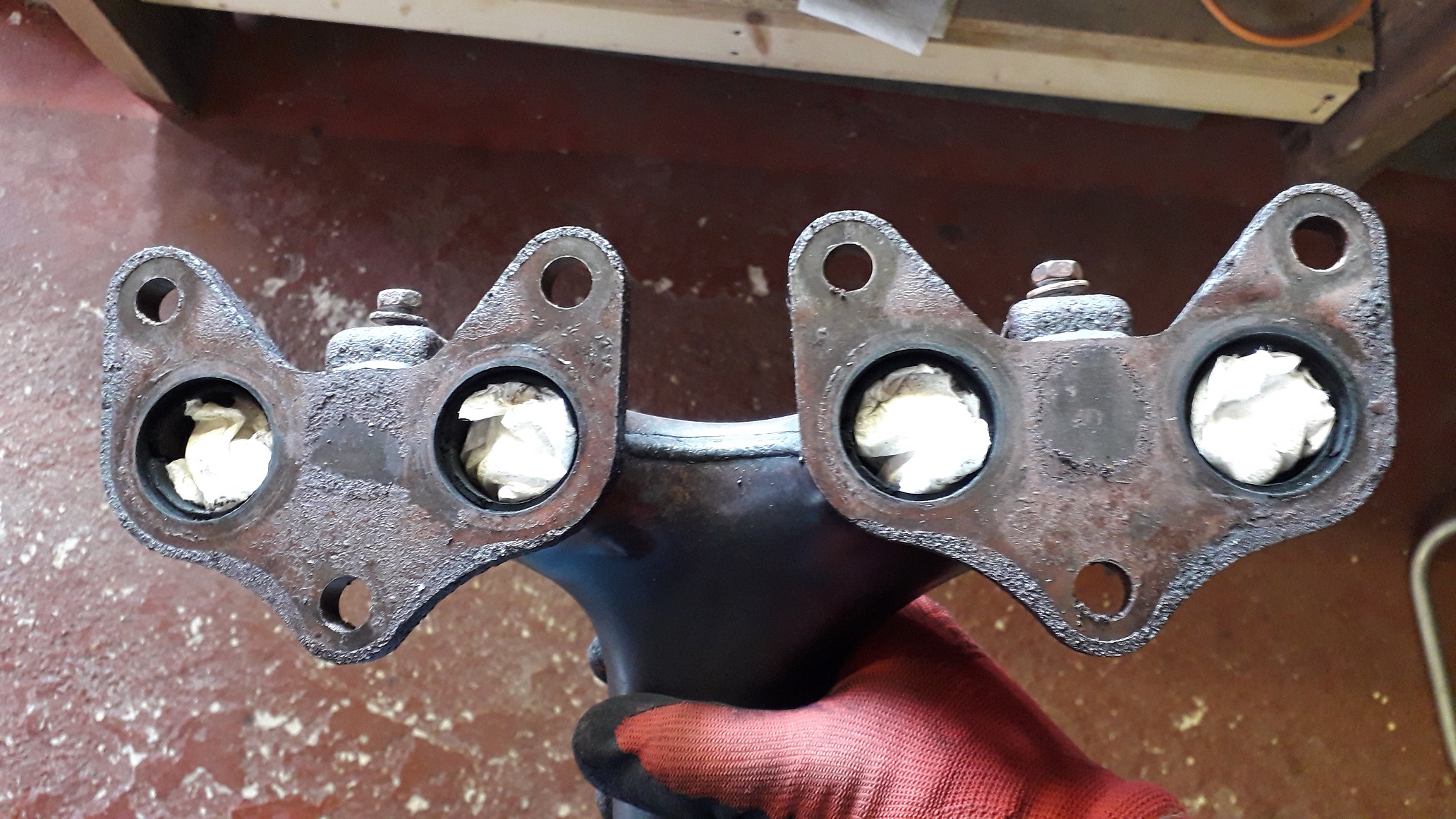
The original manifold was good and just needed the rust cleaning off the head flange with the flat of a file skimmed over it (using light pressure only) to remove the worst of the corrosion. Bolted to the head with a new, genuine, sheet steel gasket and torqued to approx. 40Nm. Supposed to be more but one of the nuts started to feel "soft" and I didn't fancy stripping the thread from the head. Bolted the original support brace to the block and then to the manifold, used 20Nm.
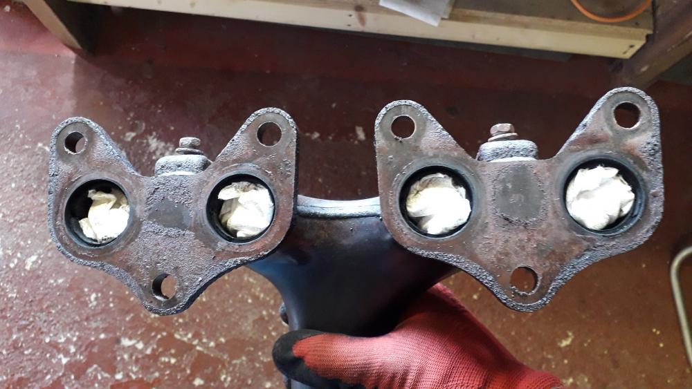
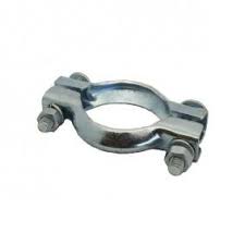
Bought a BM catalyst front half exhaust (from mani to centre silencer) and a Klarius section from cat to back box. New front and rear rubbers, needed a 47mm U-clamp for the slip joint between the two sections and a fibrous ring gasket (90917-06081) with another clamp for the back box. Used the original front doughnut seal on the manifold. Treated her to a new Denso O2 sensor also. I was lucky enough to borrow my friends pit for the install and with 2 of us involved it took about an hour to fit.

.jpg.497e21296cc160297bd38bb551ff9be0.jpg)
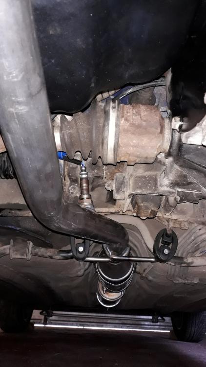
Slid the back box mount into the hanger and as I supported the weight my mate pushed the back box and its rubber mounting onto the chassis posts. I installed the new O2 sensor to the front section boss using "plenty" of torque with a brake pipe spanner. The front section bolted on easily to the mani using the shoulder bolts and springs from the original.
The fit between components and chassis was surprisingly good, the front wire mounts for the rubbers were touching the ARB initially but the weight of the rest of the system pulled it down and clear.
Centre slip joint was coated in exhaust paste on the male section and slid into the female of the silencer pipe. Slid the rear section into the back box with the fibrous washer and I added the clamp whilst my mate held the joint together. Deffo a job that requires 2 people. Aligned the sections to give best clearance to the road and bodywork / fuel tank and then fully tightened the joints. Couldn't find a 47mm U-clamp so I did the right thing and overtightened a 48mm clamp 'til it took on the correct shape of the pipe. 💪😁
All in all a good fit, no leaks or knocking and it was cheap. Hopefully the cat actually works next MOT as it's a non type approved version (not required on this age of vehicle so the cats are usually low quality with less of the unobtanium elements included). Hooked up the O2 sensor plug to the loom and also reinstalled the starlet lower intake manifold brace (only bolted to the block) as it has the clips / supports for the wiring loom. So now essentially I have a post with the alternator loom, main engine loom and O2 sensor plug supported rather than rattling around possibly causing breakage from fatigue.
Nearly there.
-
14 hours ago, Keviano27 said:
Late to the party but its a shame you had to sell parts man, glad you've carried on with the build tho, keep up the good work its a great example 👍
Thanks for the positive comments, how's yours coming on?
-
Radiator install part 17
https://www.youtube.com/watch?v=RpA2T589Y-A
The plumbing begins.......
The original radiators are 28mm inlet / outlet and the bottom hose outlet is on the passenger side. It is possible to find a Civic half rad with the 28mm inlets (GPI automotive I think?) but they were only available from Europe, so shipping costs, possible damage and post Brexit (remember that?!) changes made me go UK supply.
This leaves me with a 32mm inlet and outlet and the bottom hose exiting in the middle of the bay. The original plan was to make some custom hoses from silicone bends / reducers from 28-32mm and alloy joiners of various shapes but at the time it was difficult to get these items and the alloy bend I was sent needed to be returned as it was crap!
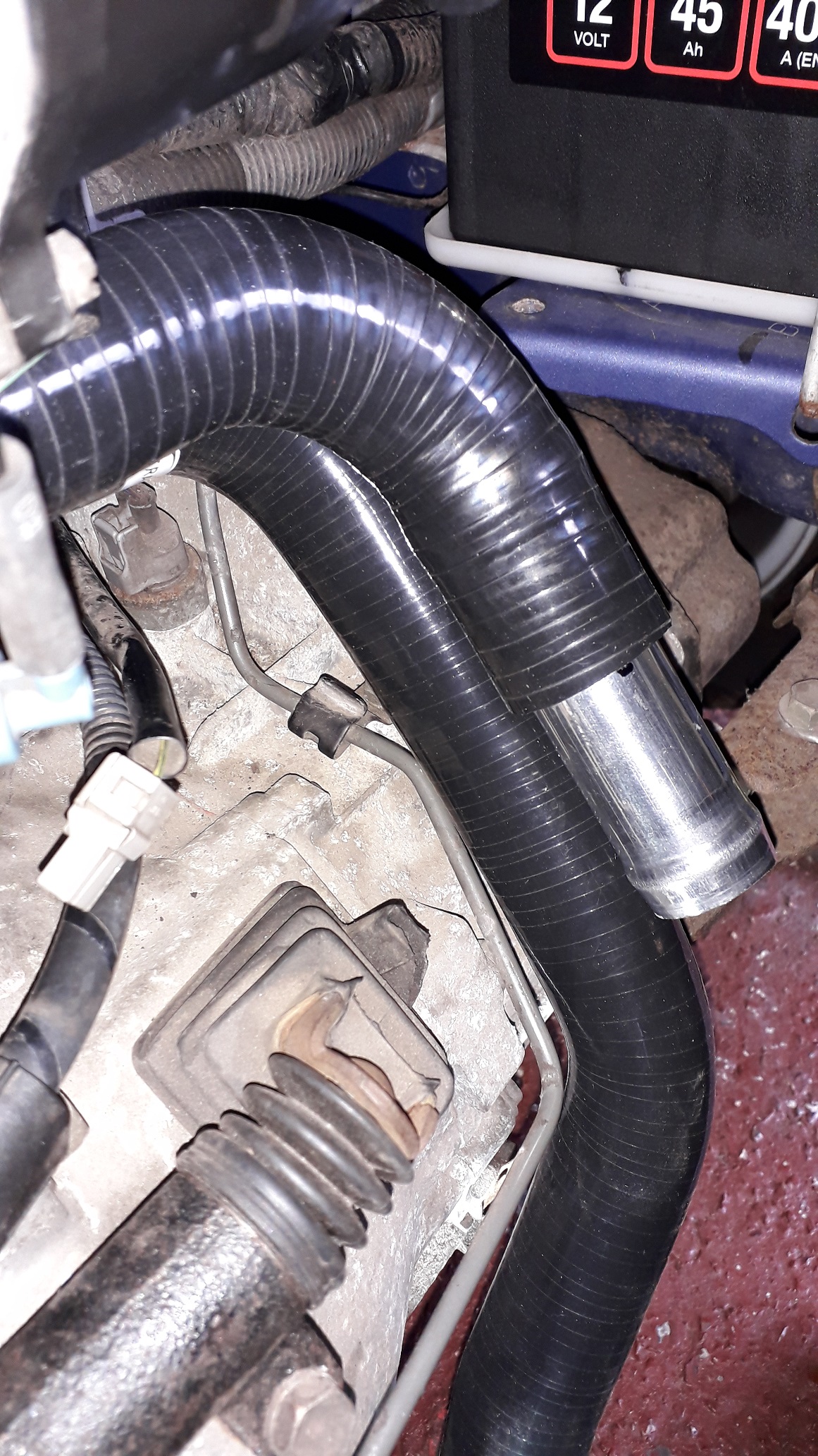
Sooooooooo, plan f involved getting some starlet replacement silicone hoses top and bottom and making the lower hose fit better as it is very common to see the top bend collapse flat as the radiator end is relocated from one side to the other.
Bought some TT racing ones from eBay, they were listed for 96-99 EP82 (wtf!) but their other listing of 89-96 EP91 (eh?!) were a completely different hose shape, so I took a punt on the picture being correct and in 10 days they had arrived. Compared to the originals they were almost identical.
Attached the bottom hose which stretched over the radiator 32mm fitting surprisingly well with a bit of car shampoo for lube and the top section fitted the 28mm thermo housing inlet fine. The top bend folded tight and halved its width. This needed improvement.

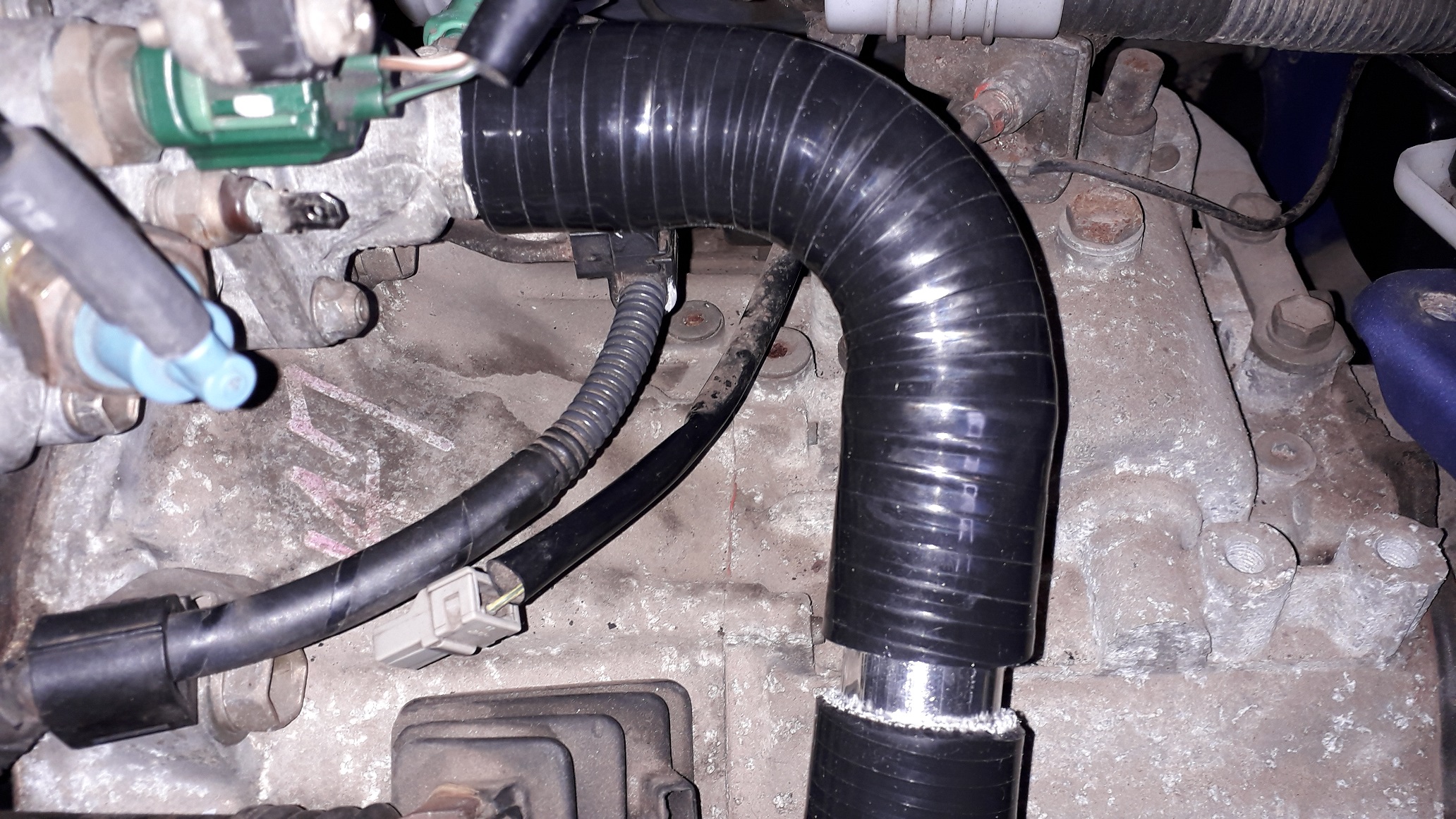
Bought a 90 degree silicone bend with an alloy coupler to correct the shape of the hose section.
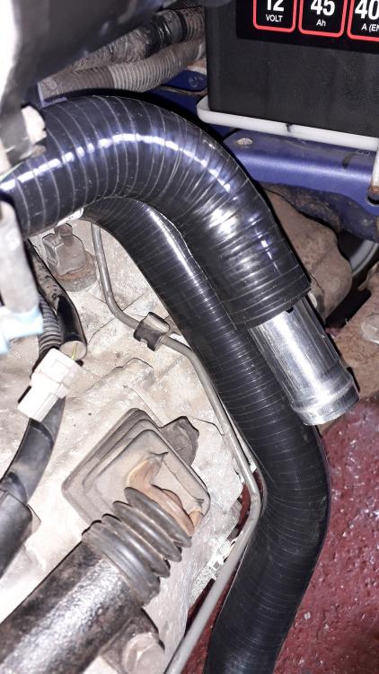
It was slightly over 90 (which helped even more) and when compared to the 45 degree stock bend it shows a good difference. Cut off the top 45 degree bend.
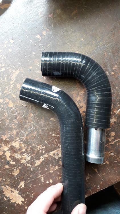
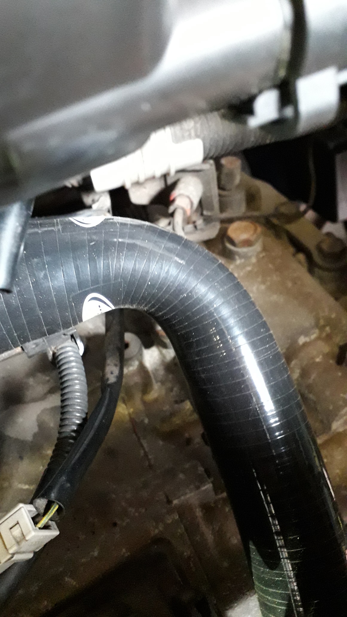
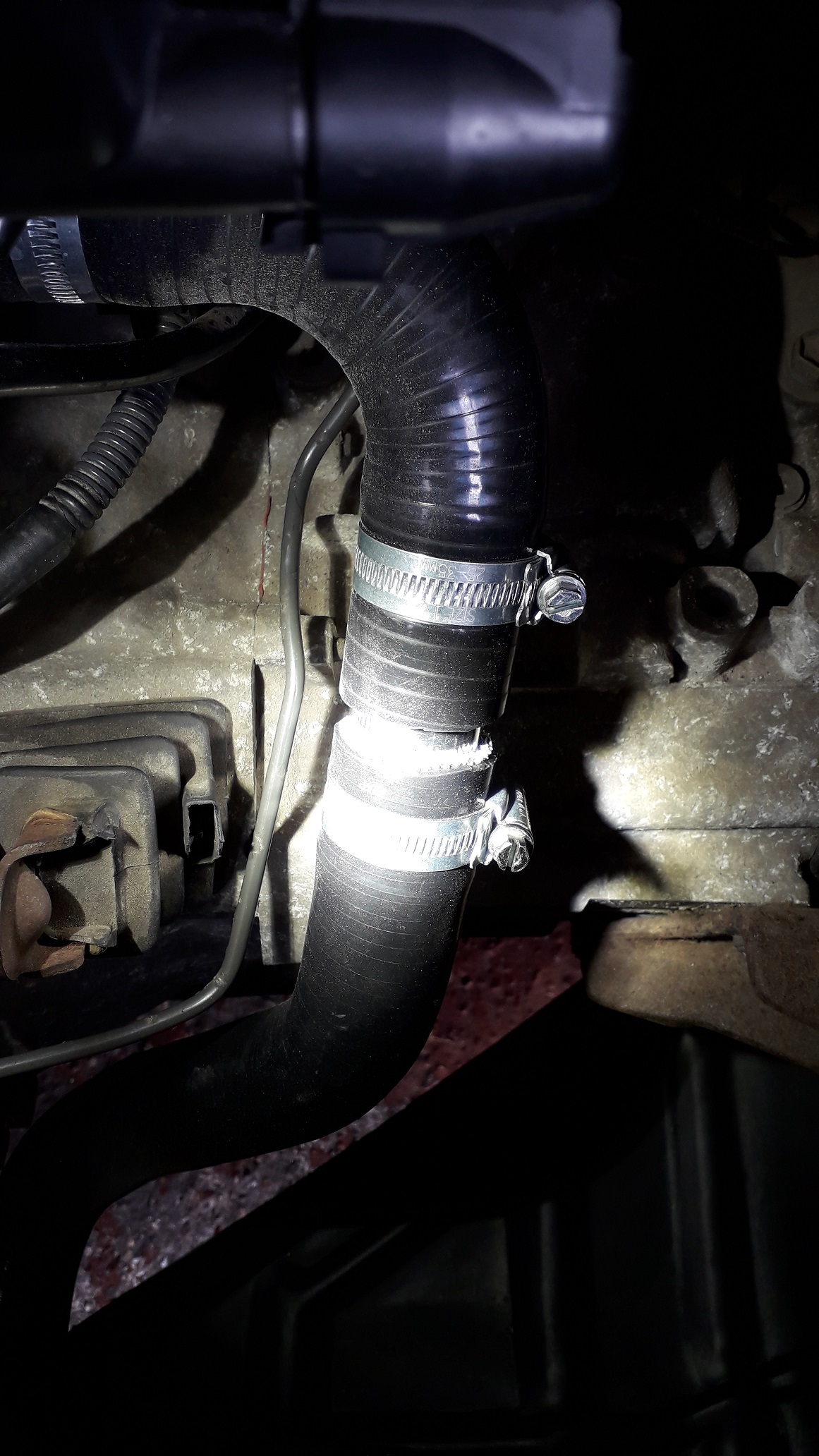
So with the new hose assembled and fitted I manipulated it to fit the new position without kinks or strain. The long alloy joiner and 2 separate hose sections allowed me to manipulate the angle of the top and bottom section relative to each other and also the length of the new hose. Simple but very effective.
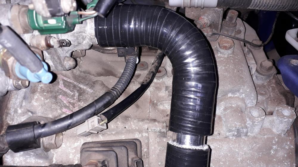
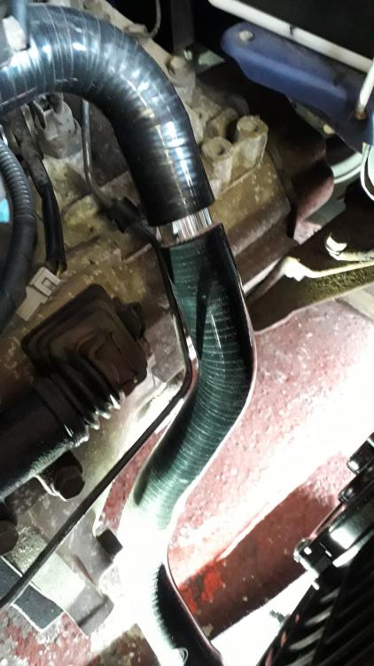
Not all moonlight and roses however as the new pipe was close to resting on the clutch slave hard line. Didn't want it to be battered whilst driving and as I was in no mood to be fucked about at this point in the build I performed an industry standard pipe clip delete and gently manipulated the hard line to the side. No clearance issues at all now.

The upper hose was relatively easy by comparison, the only adjustment was to the length of the radiator inlet straight section. It was too long by approx. 25mm so I trimmed the silicone hose and had to leave it stretched out overnight with a socket stuffed in it as it wouldn't fit over the 32mm section as delivered. Car shampoo lube and the correct amount of swearing soon wiggled it (permanently, I think!) into place. The overflow pipe was connected to the Glanza bottle with cable ties just in case. All spring clips replaced with worm drive clamps.
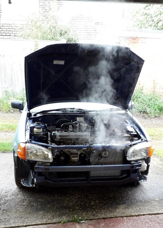
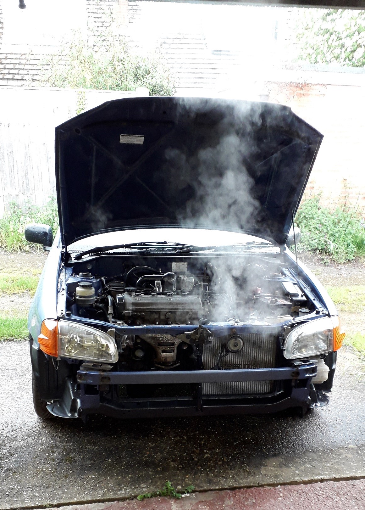
Topped up with Toyota red coolant (nearly 5l) and proceeded to burp the system. I read a helpful topic on this forum about it and basically, engine off, heater to hot setting, with the rad filled and the overflow bottle connected and filled to the full mark. Remove the rad cap and push your palm down on the rad filler neck to seal the top. Then squeeze and release the upper and lower radiator hoses to "pump" the coolant round the system. Squeezing pushes the coolant around and the air out into the overflow bottle (bubbling occurs) and when you release the hose it draws in coolant from the bottle to replace the air. Repeated until there was no bubbling. Rad cap off, started engine, ran up to temp. fan cuts in and out, bottom hose hot, engine off, rad cap on, leave to cool. The system should refill with coolant from the overflow if necessary.
Was a bit worried as I could still smell and see coolant on the rad and thought I had a leak, turns out it was simply coolant from the burping / filling process still stuck in the fins / louvres. So I hosed the coolant off with fresh water and warmed it up to temp. to evaporate the water. No leaks.
That was exhausting......
-
4 hours ago, burty said:
Yeah I love mine it's nice to be able to use the full rev range and not be breaking the law sounds lovely with the tte back they really are so much fun
Body work on mine ,slow first off jr spray booth broke then lockdown 2 happened and had to furlough his staff do basically he's just cutting the rust away and has made some rear arches out of front wings I do have pics but want to out before and afters up
I've just been enjoying my Celica till it goes up for sale
Yeah that's the fun of lower powered cars on a twisty B-road, full throttle most of the time, with a grippy chassis at relatively low speeds and still a smile on your face.
Looking forward to the updates on the SR, it has a great story behind it and your really doing the right thing by her. Wish I had kept some of my earlier cars too.
-
12 hours ago, RobSR said:
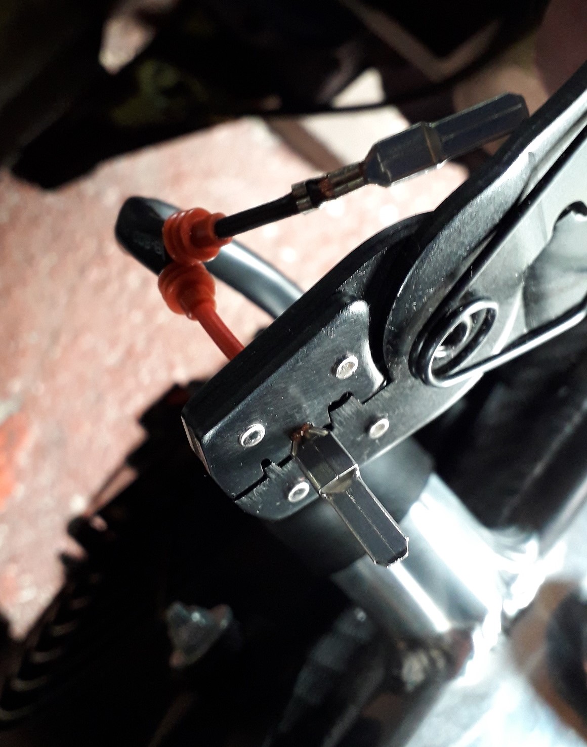
Nicely done, just as an FYI you crimp the weather seal into the “strain relief” tangs on the contact as one 👍
Thanks mate, every days a school day 🤓.
It would make sense not to have to push them into the plug afterwards. Still felt like they'll seal fine with a manual input. Thanks for saying, I know for next time 👍.
-
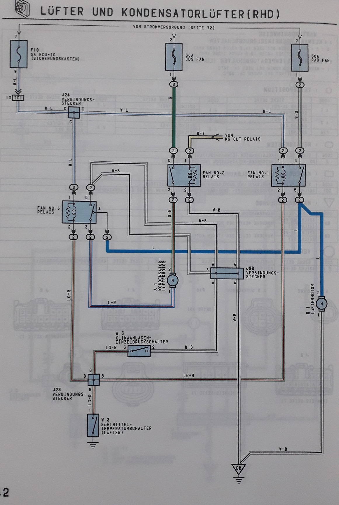
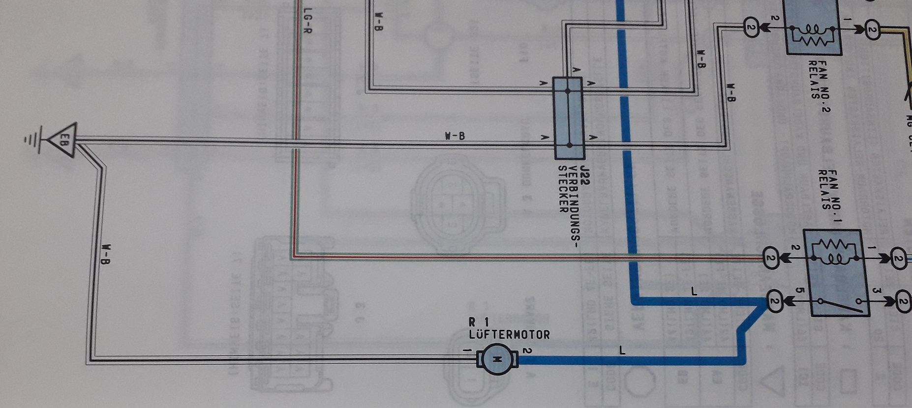
Radiator fan wiring.
https://www.youtube.com/watch?v=RpA2T589Y-A
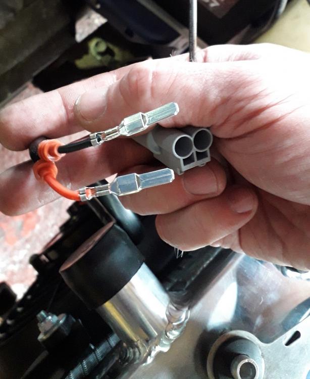
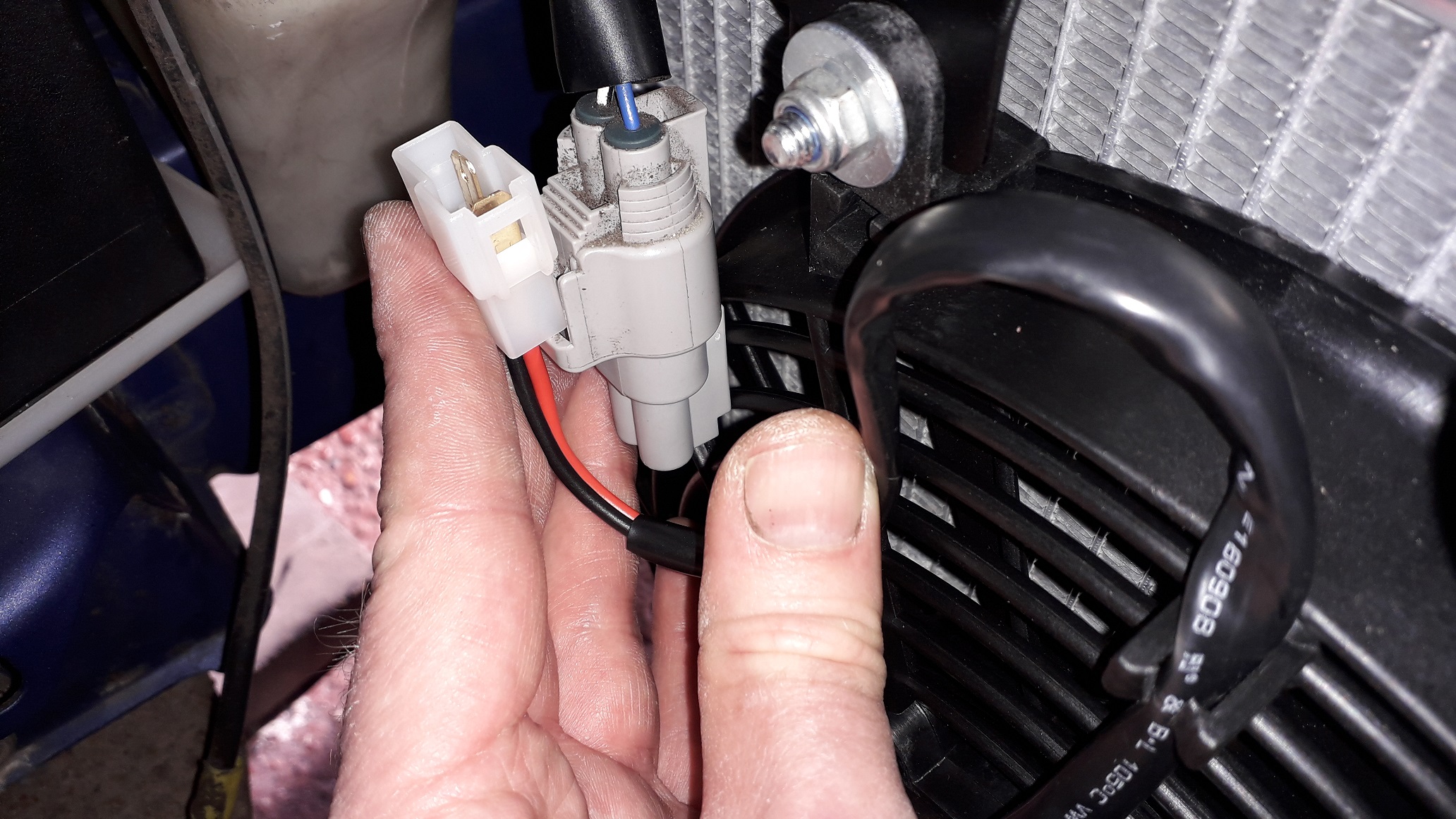
Bought a Toyota rad fan plug and pin set from the usual source. The fan comes wired as a puller setup (mounted in engine bay) with the red wire as + and the black as -. You can swap the fan round on the motor to make it a pusher or reverse the wires and run it backwards if mounting outside the engine bay.
Check for reach before cutting the supplied plug off the rad fan wiring.

Chopped off and then stripped and crimped on the replacement flat blade style contacts. Don't forget the rubber seals first. Pretty sure you could use generic spade crimps and just push them into the Toyota loom plug, they look about the correct size.

Crimped up well, as did the strain relief crimp to the sheath. Double checked the Electrical workshop manual before inserting the contacts into the plug housing. They clip in with an arrow tab to hold them in place and then a plastic collar is inserted to keep them there. Plugged the weather seals in also.
🤓
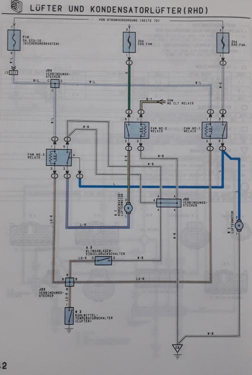
Toyota loom wiring = White with black stripe is - (earth) and blue is +. So for me it was black to white and black. Then red to blue.

Double checked the fan wiring with a 14.4 volt drill battery using some female spade ended jumper wires in the plug. Fan direction was correct, pulling cold air from outside the engine bay through the radiator.
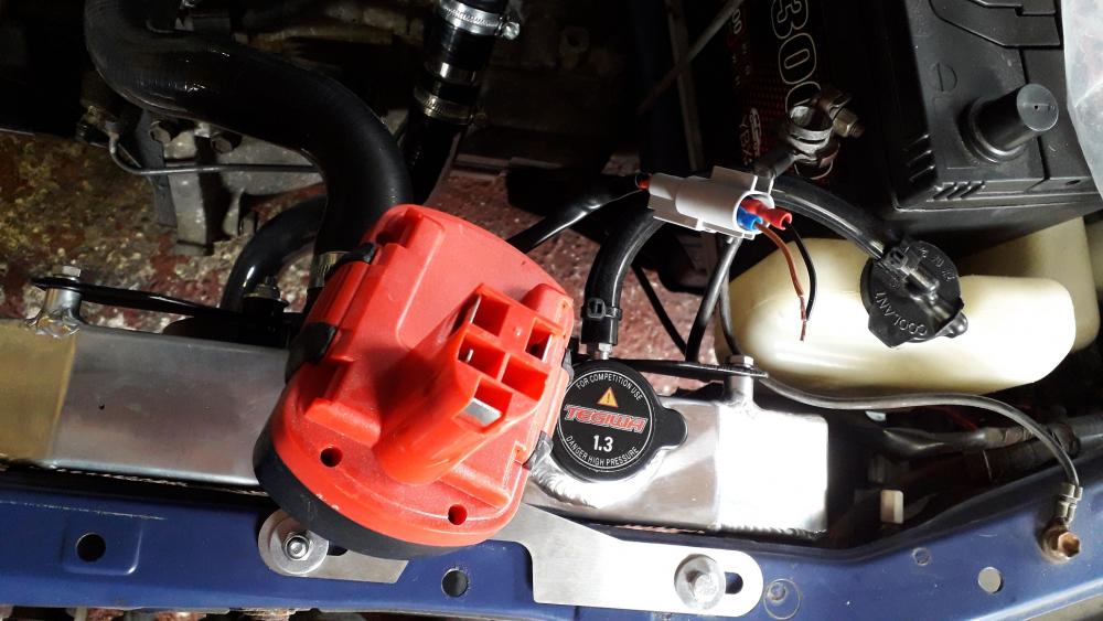
Connected up, wire secured into clip. Had to mount the fan with the wire exiting the motor at the top or the wire was too short to use the clips and was close to straining.
Plumbing next.
-
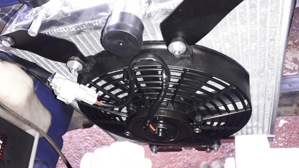
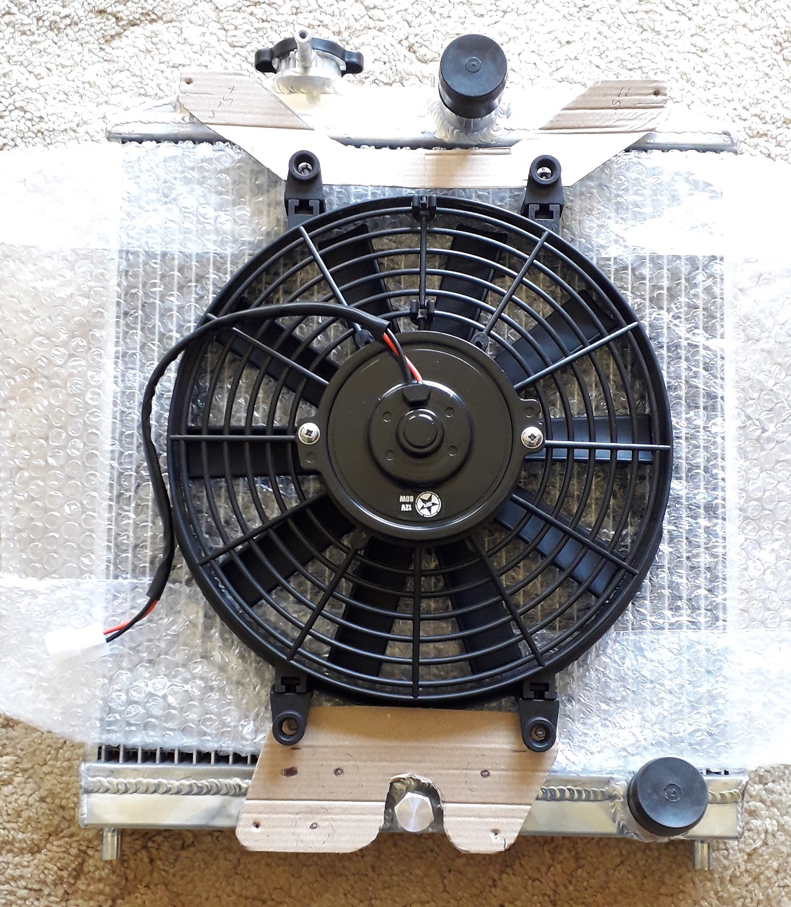
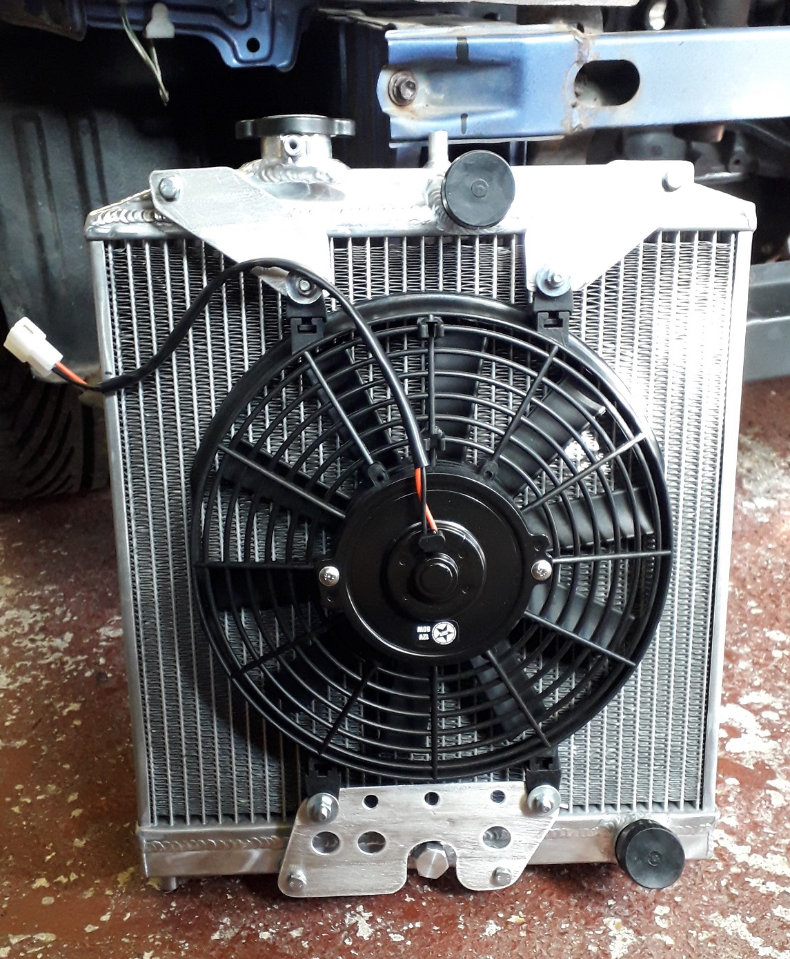
Radiator fan install
https://www.youtube.com/watch?v=RpA2T589Y-A
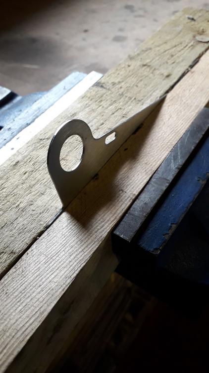
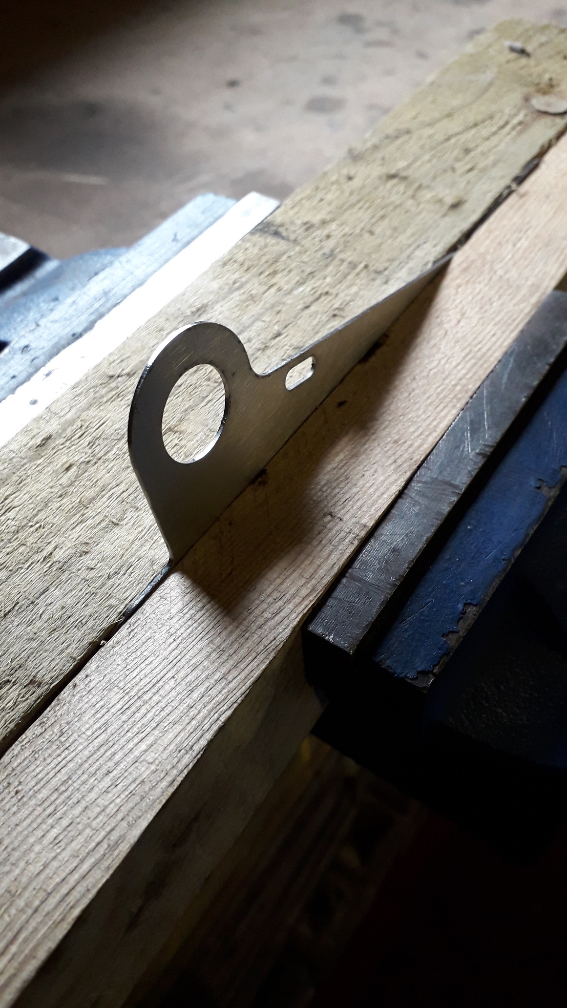
Chose the generic 10" slimline 12v 80w puller fan. Went with the straight blade design as these are more efficient for their size but are a touch noisier than curved blade designs. No cable tie mounting kit but I was always planning on making some brackets.
Cardboard templates made.
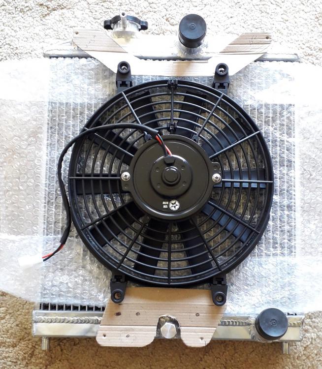
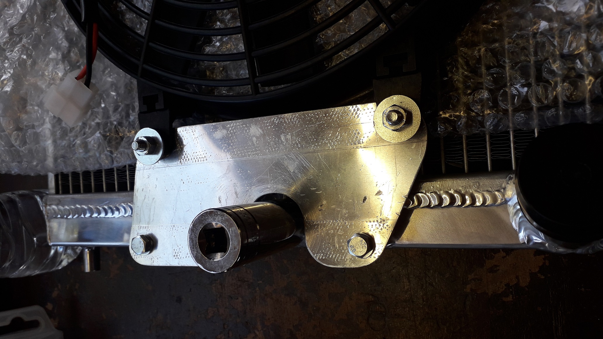
Moved the design over to some 2mm alu sheet. Cut a large access slot in the lower mount to be able to use a thin wall socket on the drain bolt. Decided to have both lower mounting points on a single bracket which allowed the upper mounts to be individual (smaller and easier to make).

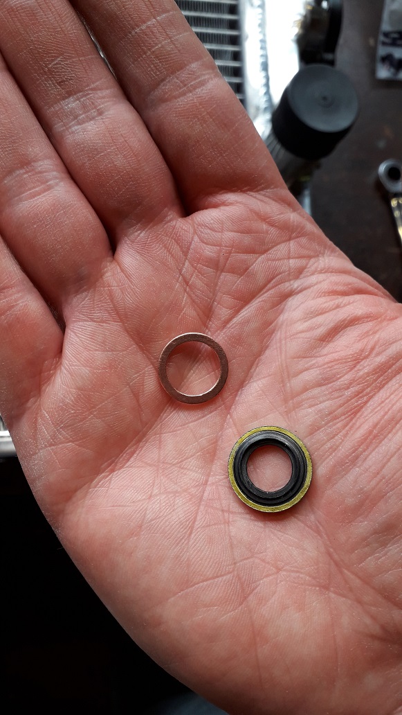
Replaced the drain plug dowty seal with a copper crush washer and added 277 thread seal just in case.

Bracket mounting surfaces for the rad and fan needed to be offset to keep the fan off the rad so were swiftly bent up in the vice. All fixings M6. Drilled for lightness and airflow.
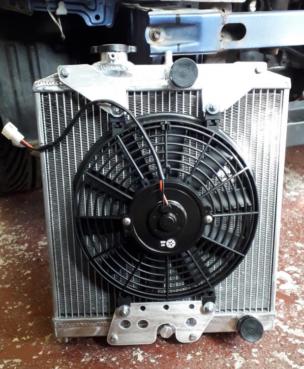
Sanded the surfaces down with 80 grit to remove the vice jaw marks and painted with acid etch primer and satin black.

-
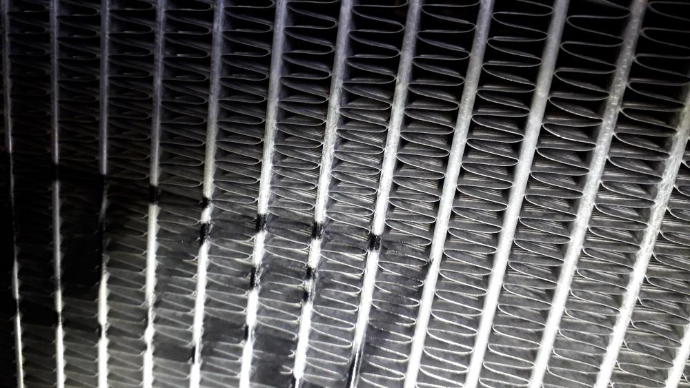
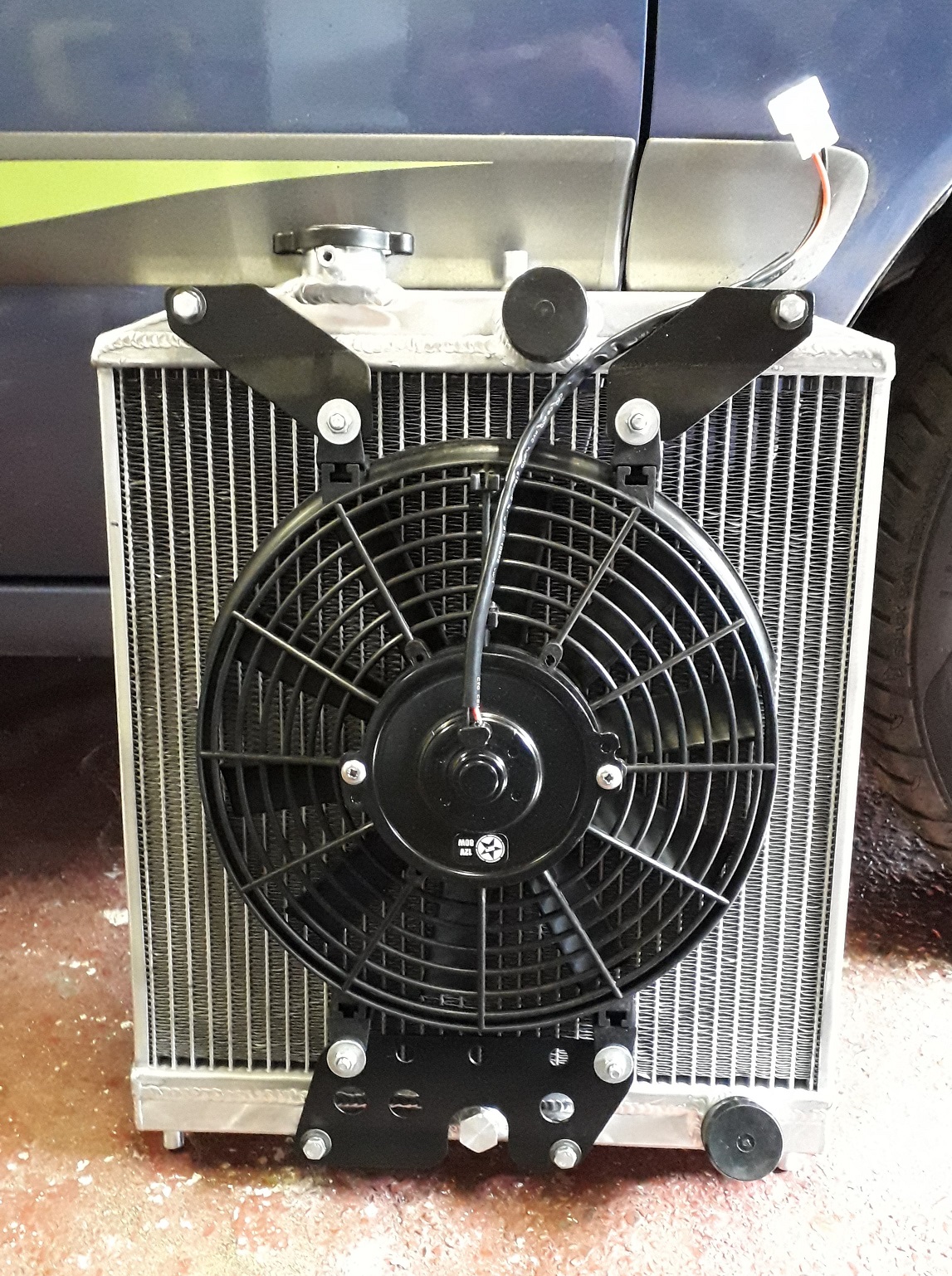
Civic half radiator install, part 1, brackets.
https://www.youtube.com/watch?v=RpA2T589Y-A
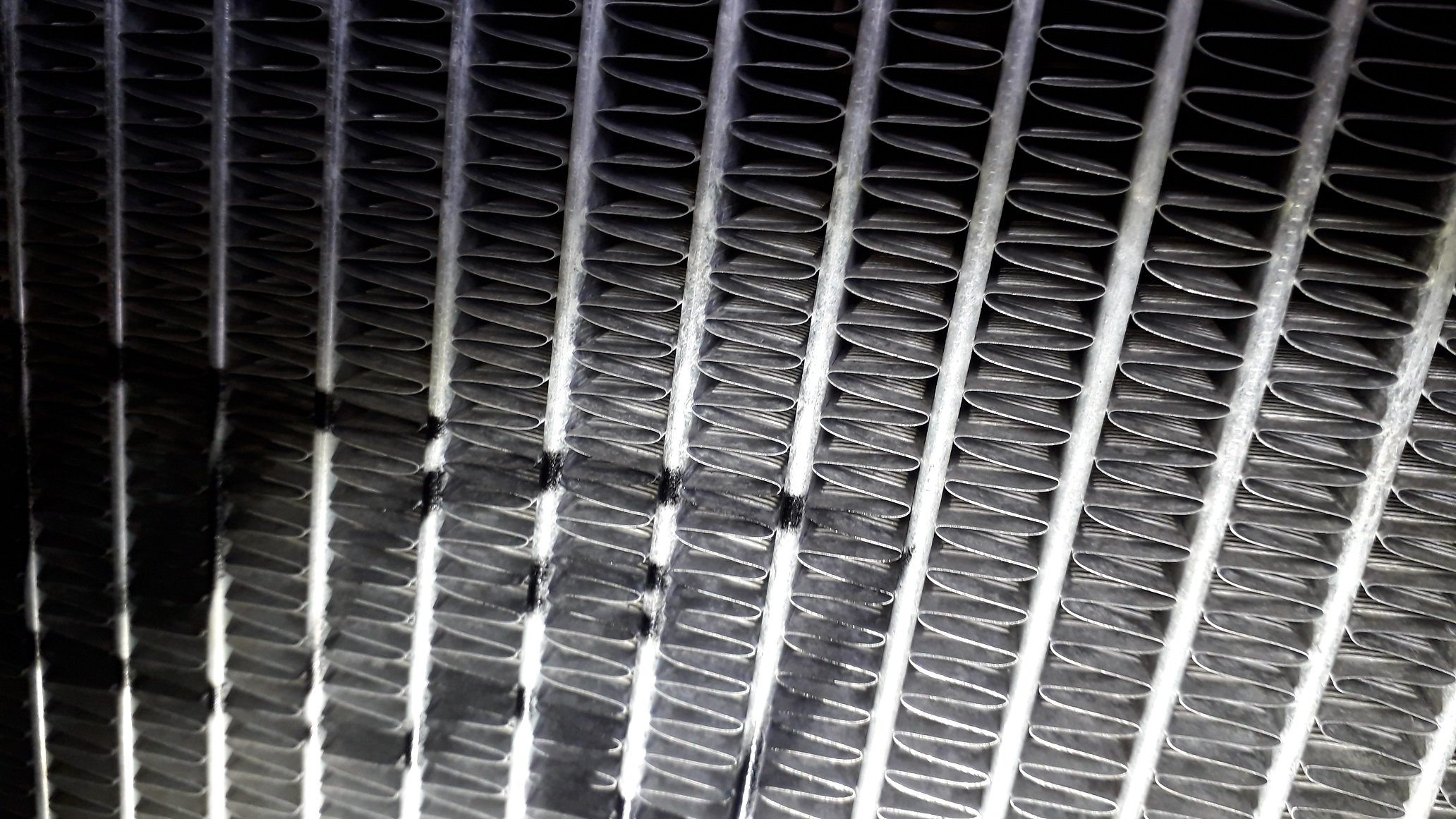
So after removing the knackered original Toyota radiator and its mounting points it was time to install the Civic half radiator and bracketry. Chose a Tegiwa dual core radiator as it was on offer and is UK supply. Quality was OK but at least the fins are louvred to help increase surface area. The brackets were the cheapest on eBay.
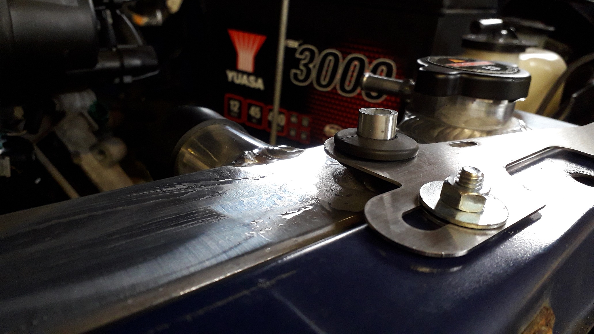
Bolted the lower bracket onto the front cross member using the 2 x m6 bolts into the freshly re tapped undertray mounting points and the upper bracket to the slam panel. Closed the bonnet to check clearances and it was all clear.

The upper mount bracket is flat and therefore follows the angle of the slam panel and angles up slightly, didn't really secure the radiator so I clamped it between the soft jaw 3000's and folded the rad mount side down a bit to follow the angle of the radiator top and add some pressure to hold it down.
Replaced the supplied upper grommet as it was too large for the rad mounting post which allowed the rad to wobble around.

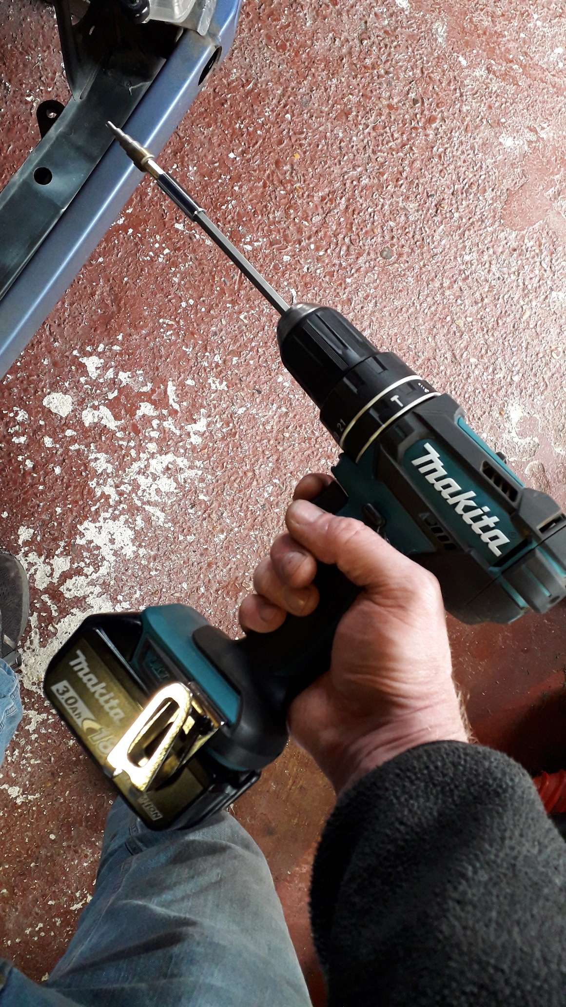
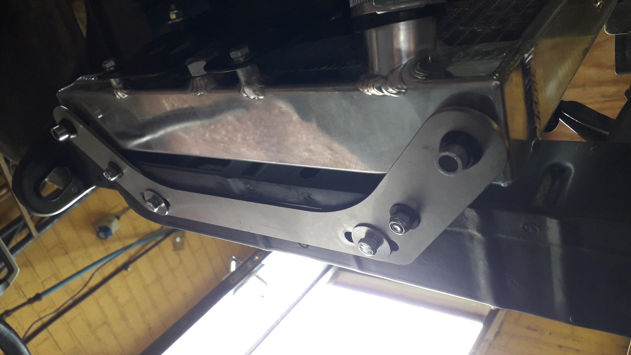
Wasn't keen on only having 2 bolts holding the lower bracket and they are also a reasonable distance away from the load they are supporting so I added 2 more m6 bolted fixings into the lip inside the engine bay. Using the "contraption" from the overflow tank install I drilled the very wobbly holes.

Removed the lower bracket and drilled it also.
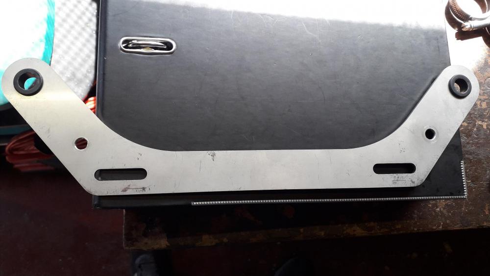
Bolted into place, alot less leverage on the original fixings. Also shimmed the original mounting points down away from the cross member with some washers to put the lower bracket closer to horizontal.

-
4 hours ago, Sam44 said:
great to see this build continuing.
i was gutted to read that parts had been sold.
That is the engine sensor earthing bank behind the manifold. what i have done is to run an earth return wire to the battery. sharpens them sensor signals up also run a earth return wire 6 to 8mm diameter from the battery to the cylinder-head for the spark plugs, and last one from the battery to the bulk head (this is were most of the in vehicle earths run to).
the battery/chassis earth return on this vehicle is poor.
what is the difference on the cranks. i was told the 4e marked crank is lighter compared to the 4et.
I'm always cautious about moving earths from engine to battery/chassis especially when ECU / signal grounds are concerned hence leaving it connected to the engine as Toyota manufactured it.
The current chassis ground setup is a little weird. Never seen a European car need all these unsightly spider cables attaching everywhere, maybe its a JDM thing?

Not sure on the differences in cranks haven't seen a 4efe one to compare. Plenty of discussion on the forum but couldn't seem to find any real investigations other than visual. People use both for big horsepower builds but if Toyota went to the trouble of making the change for the fte there must be something in it. I'd prefer one if I were going forged and big bhp.
-
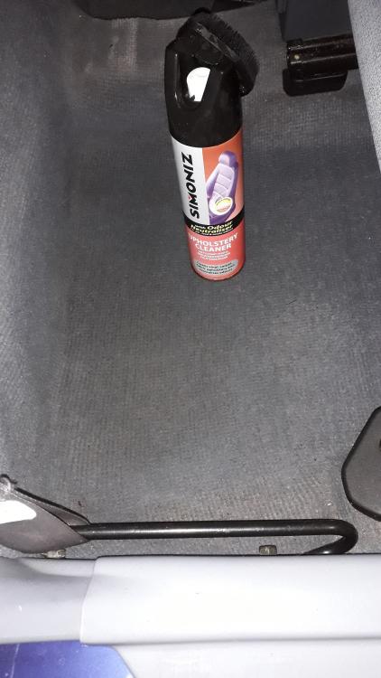
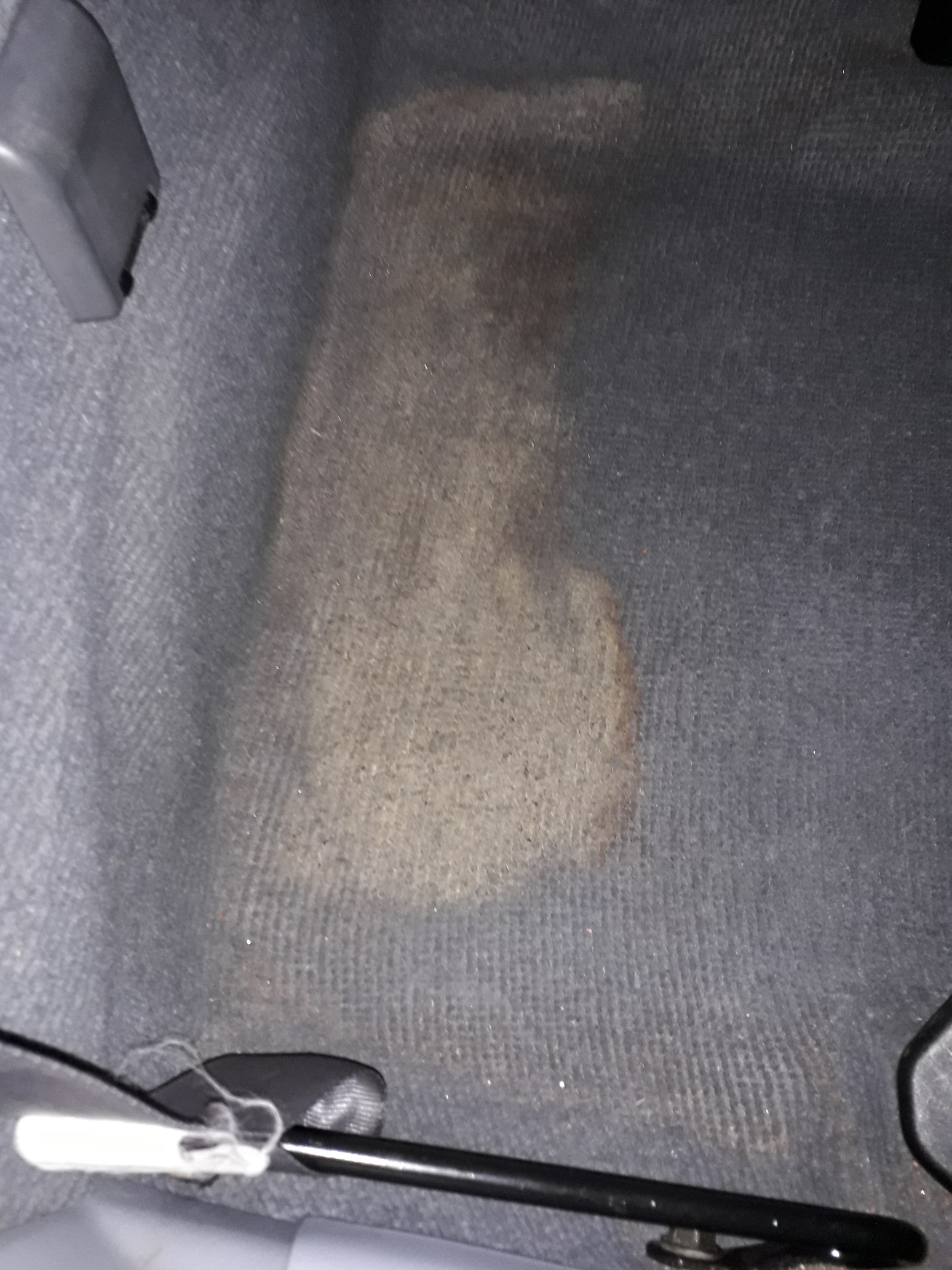
Mystery stain removal time


Since purchase there has always been a dry stain on the drivers side, rear carpet section. Unsure of the origin or makeup of it, but it needed to go!
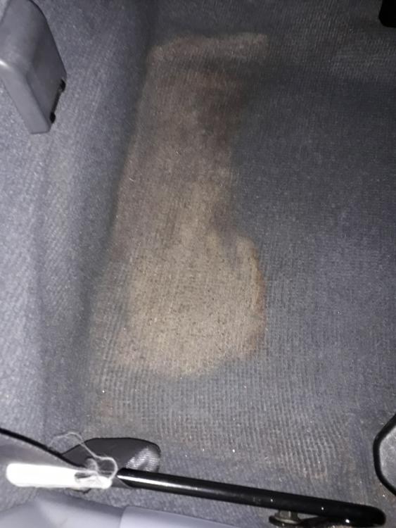
So I pulled the can of Simoniz upholstery cleaner off the shelf and had at it. Its a spray on foam cleaner with brush attachment. Spray on and allow to foam, brush in and repeat a few times. Then rinse with damp cloth, soak up residue (🤮) and dry with hairdryer. Vacuum afterwards. After the first round the stain was almost completely removed, it never ceases to amaze me how effective it is, saved the need to remove the whole interior and after another few rounds I think it'll be good as new.
-
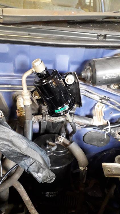
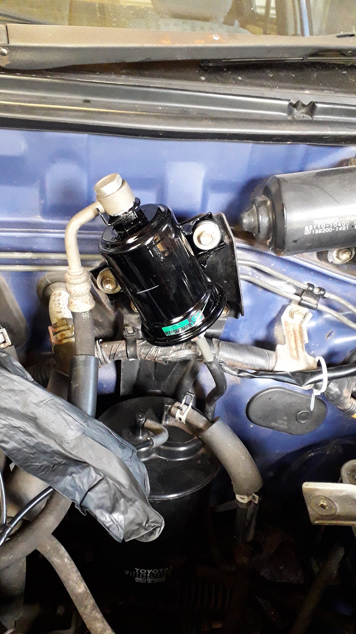
Toyota Fuel filter install.
Seemingly years ago I removed the fuel filter to replace it, after the problems with the fitment of the Blueprint pattern part replacement I decided to go Toyota o.e. and after paying £40 and waiting 3 weeks the filter arrived (new crush washers are included). Part number: 23300-19495.
I added some aluminium anti-seize grease to the lower flare fitting threads and tightened it in using a brake pipe spanner on the pipe fitting to prevent any rounding off. The thread class used on this fitting is very tight and the threads felt like they were galling almost immediately. Had to use more force than I was happy with and "back it off" a few times to keep the movement going but its in, bolted up fine in the end. Personally I don't like this style of filter and would much prefer a barb and hose clamp version. If I ever have to change it again in my ownership I will replace it with that type and modify the pipes to suit. Top banjo and crush washer fitting was a dream to attach by comparison. Bolted to the firewall bracket.
The return line from the fuel rail was looking a bit crusty so I replaced it with some Codan J30 R9 in 1/4" (6.3mm) its rated for fuel injection use and even though the return line doesn't run at this pressure its a quality hose I'm comfortable using and suitable for E5 and E10 ethanol blends that we get as pump fuel in the UK. New hose clamps also.
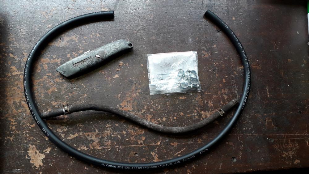
I would have replaced the feed line aswell but it's a Toyota only wacky design, another job for replacement down the line with barbed banjos and fuel hose / clamp solutions.
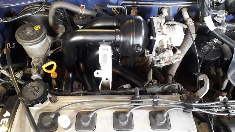
Cleaned the lower airbox and re-installed, new filter and top of airbox with intake hose. Thankfully it all fits and mates to the corrolla manifold + starlet throttle body without mods . So
for that. Re-connected the IAT sensor also.
.thumb.jpg.f2a00ada7ae91552719cc43759f3bb1e.jpg)
-
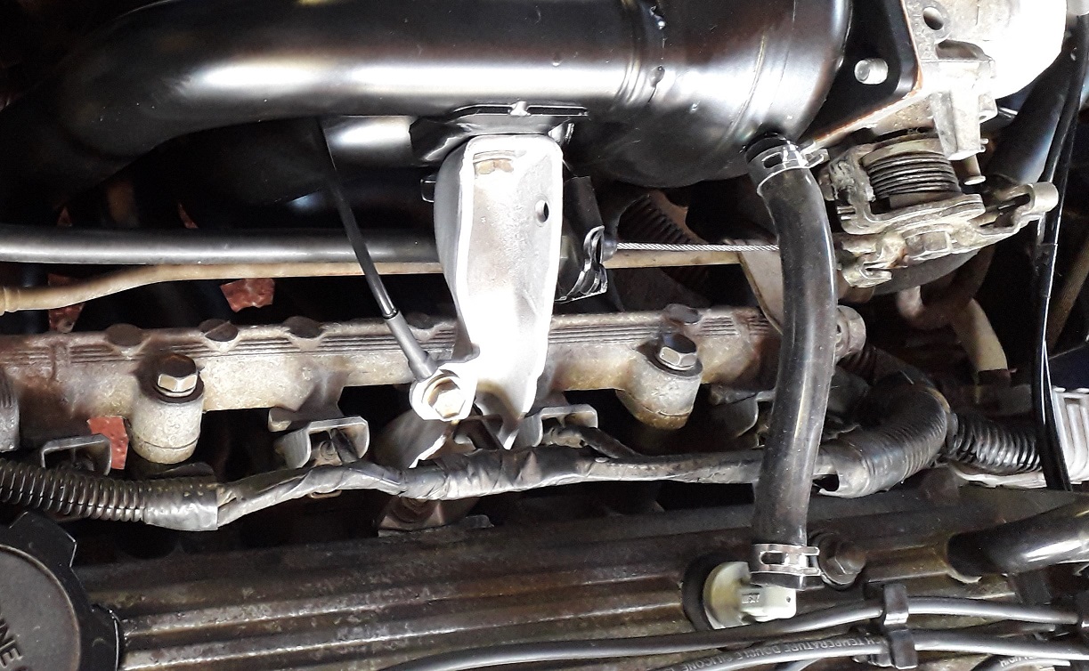
Corolla inlet manifold install.
After removing the fte manifold I replaced it with the 4efe corolla tubular steel item.
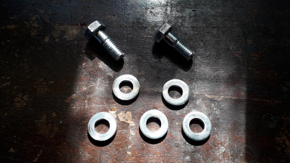
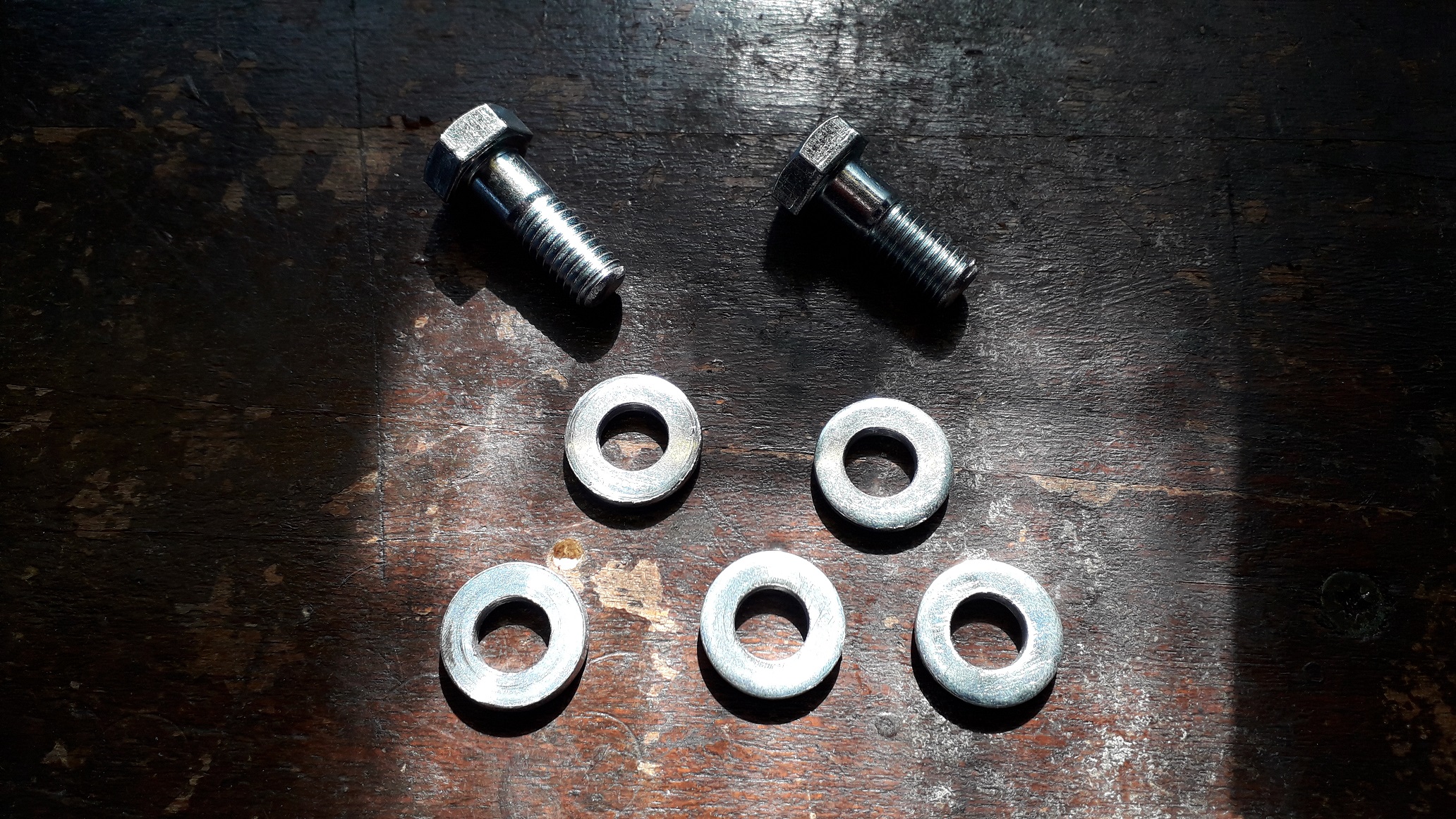
Firstly the head flange is thinner than the cast alu stock fe and fte manifolds so I made some shorter bolts for the lower fixings and added some thicker washers to the top studs to prevent the nuts bottoming out on the plain shank of the studs, torqued to 19Nm. New gaskets for head and throttle body.
The upper manifold brace has the same part number for fte and the 4efe corolla mani so I used the upper fte brace to the head. m 8 bolt and nut torqued to 20Nm.
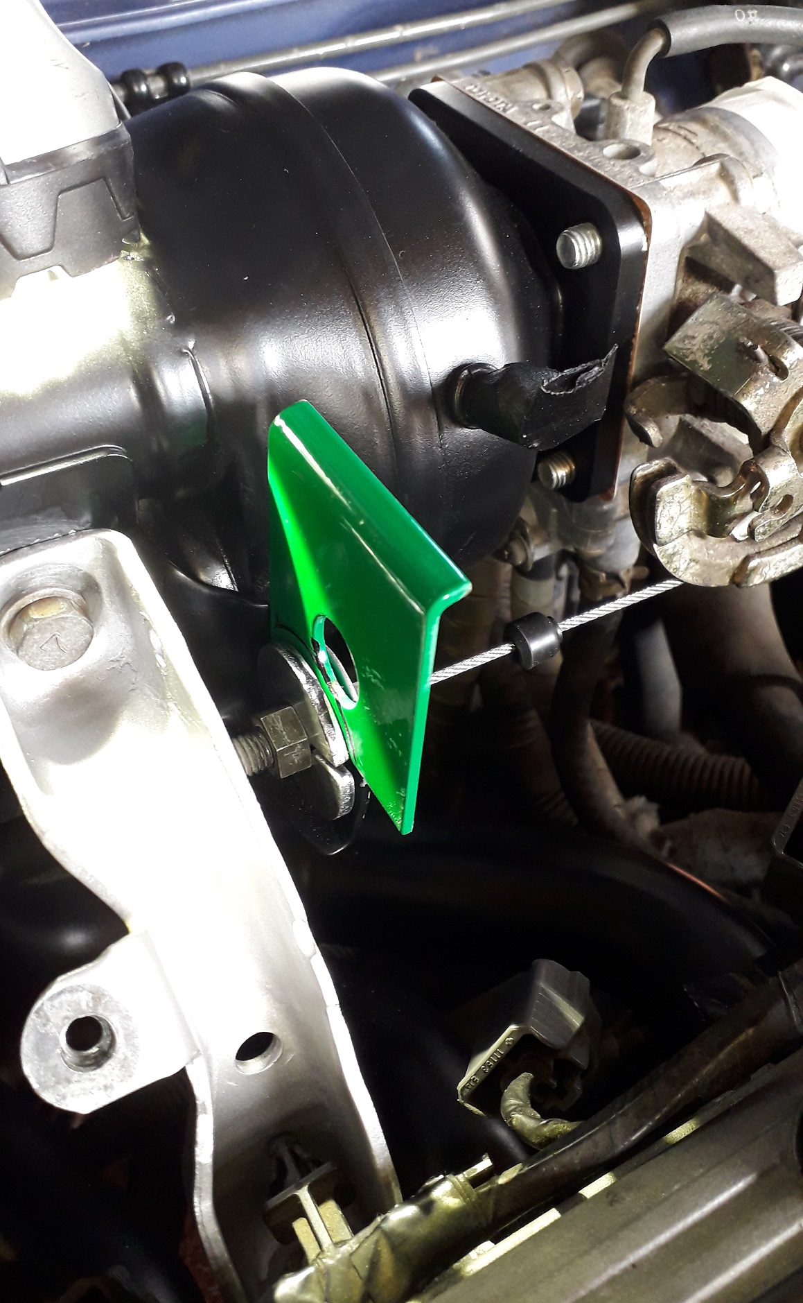
After attaching the throttle cable (which is slightly too long but workable) with two m 8 x 30 washers with a slot to fit over the cable it became apparent that the angle of the cable to the throttle plate quadrant was not good. The cable itself enters the sheath at angle and would have rubbed constantly in use, damaging the cable. So I angled it back with a piece of steel wedged in as a trial to confirm the correct thickness required.
I cut and folded the steel to clip onto the mounting washer and reassembled the cable to the manifold clamping it all into place. With the throttle pedal partly pressed down the cable now enters the sheath at the same angle without chaffing.
")
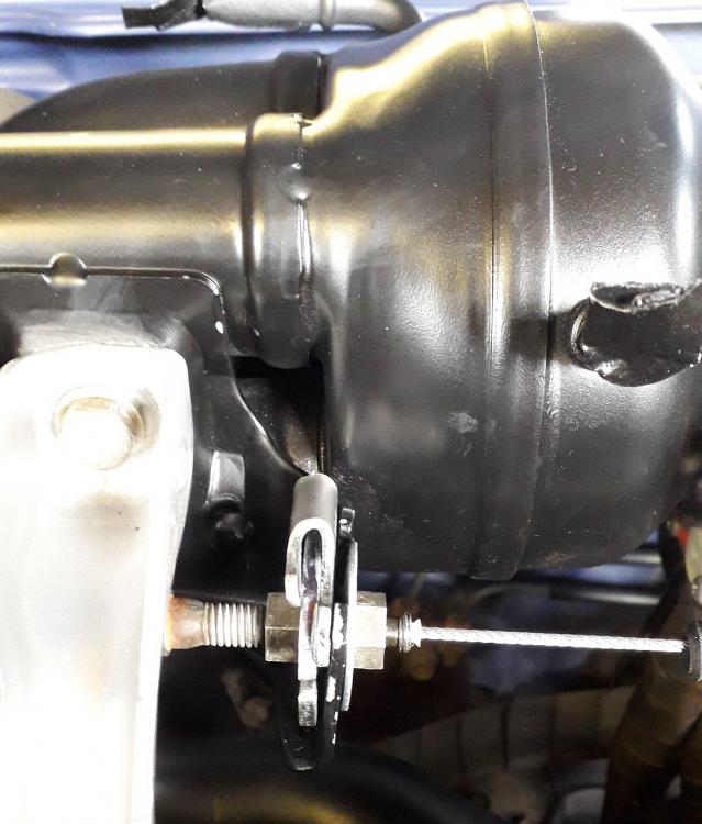
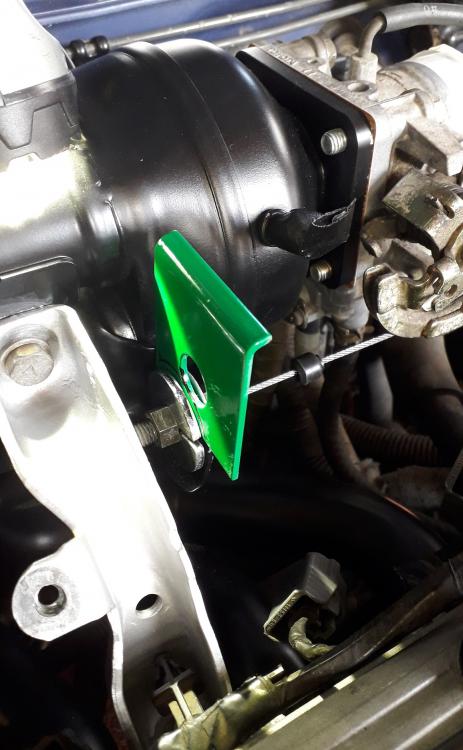
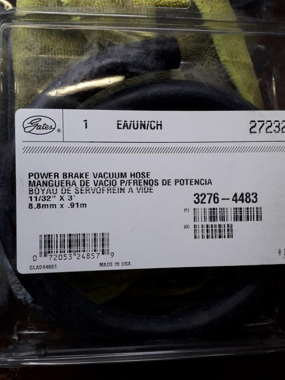
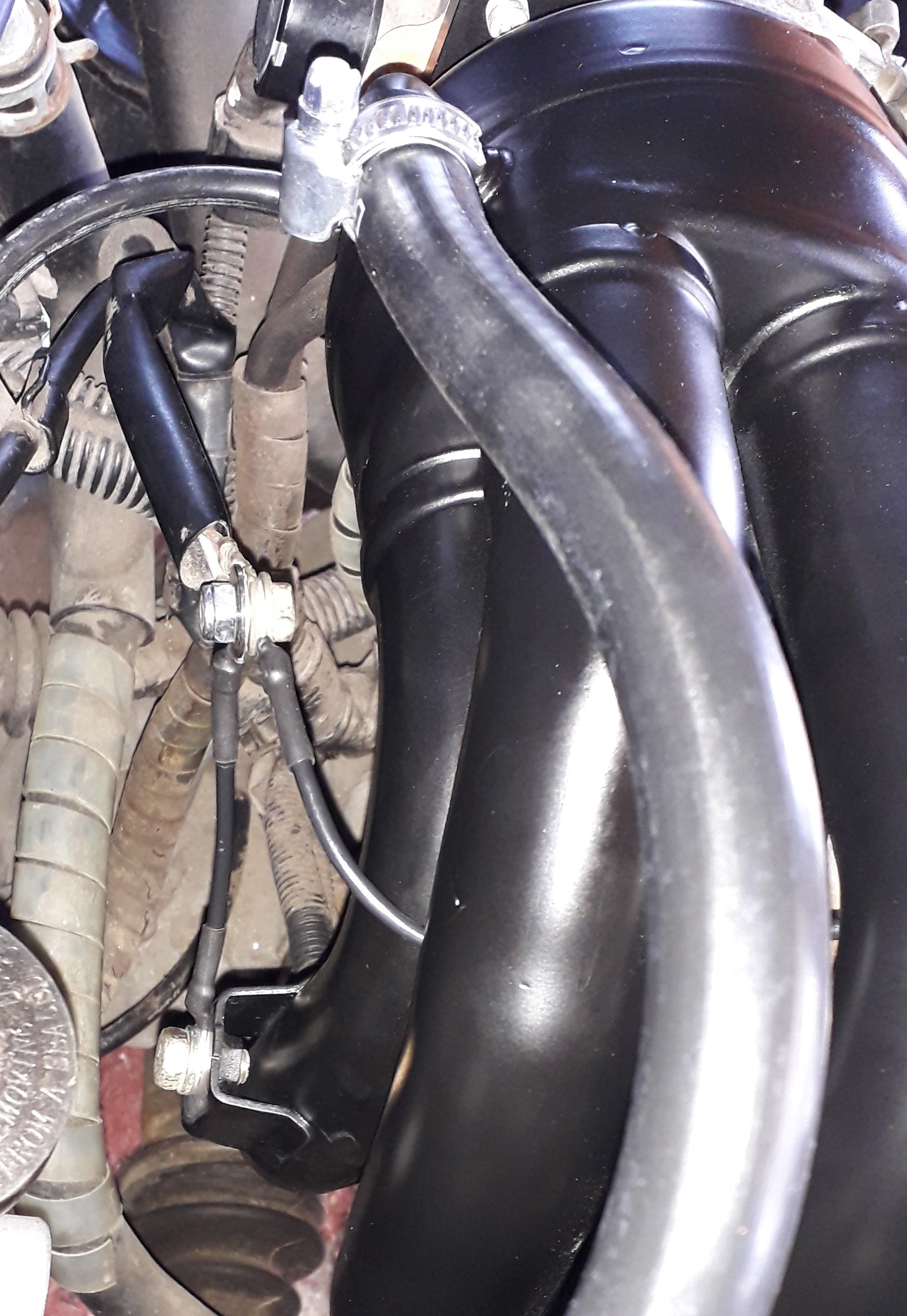
So.... onto the plumbing aspect of the install, the MAP sensor hose was replaced with a longer item (3.5mm bore) as the starlet hose is too short. I also replaced the brake booster hose with some Gates hose specifically for the purpose (deffo not silicone hose!). Worm drive clamps to replace the stupid spring clips.
Next was the earth wiring. The original earth contact that attach to the starlet manifold has a 6mm hole. Decided to make a pair of jumper wires to join the 6mm hole to the m 8 nut on the rear of the manifold and an additional to attach to the upper brace rather than cut off or drill out the original contact.
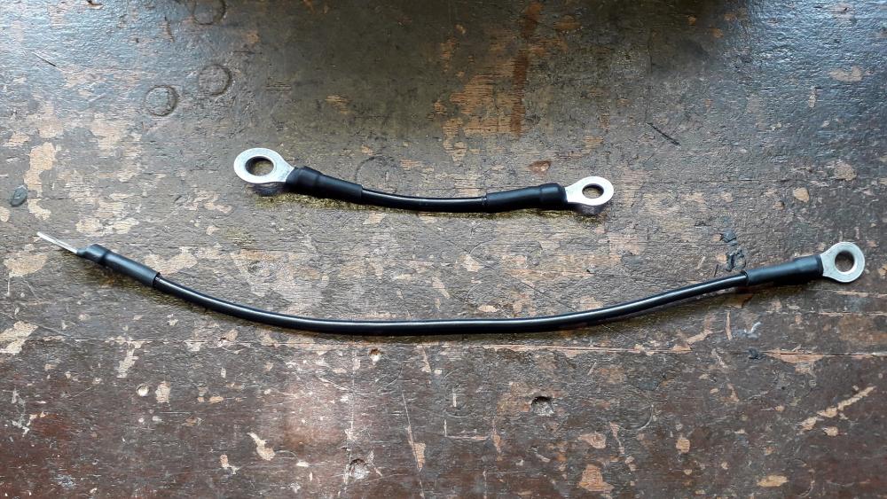
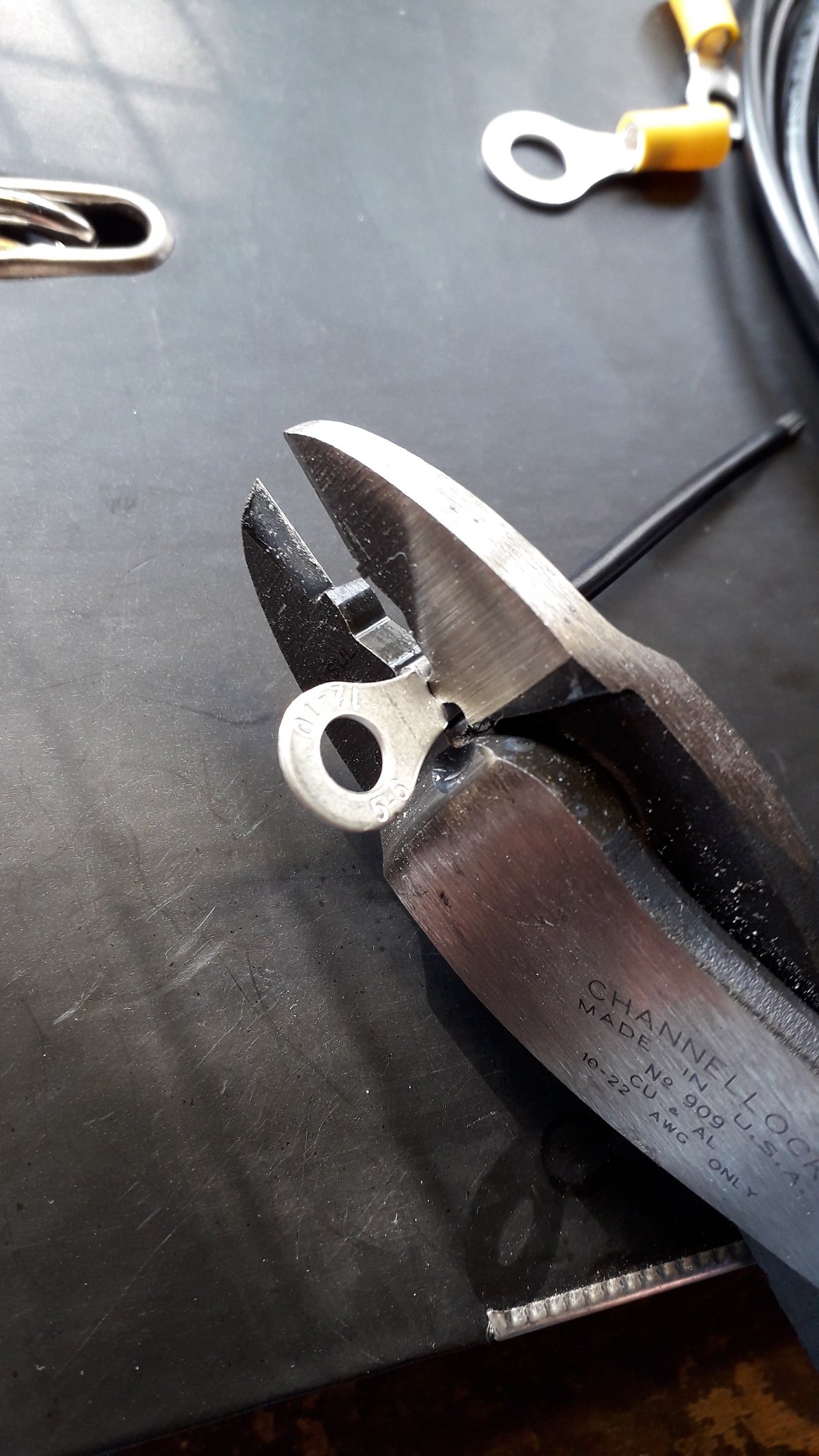
Removed the insulation from a "yellow" ring connector as they were prone to sliding off once crimped anyway.
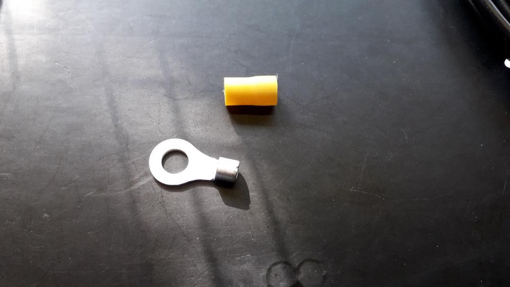
Used the uninsulated jaw of a set of channellock pliers to crimp the connectors to the sections of 12AWG marine grade wire.
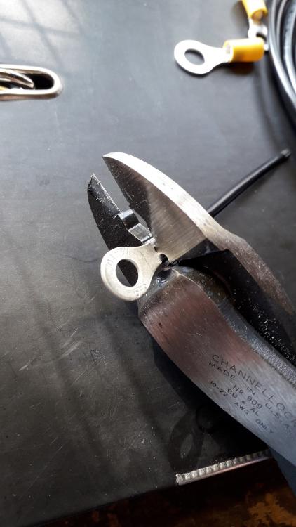
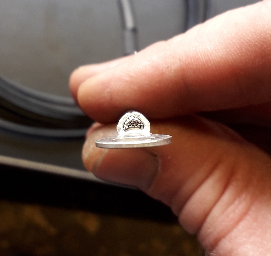
I find the "tooth" section of the jaws provides a stronger more stable crimp.

6mm to 8mm and 6mm to 6mm rings (90 degrees orientation to each other) to suit the bolt locations. Heat shrunk, ready to fit.
Bolted to the original earth wires contact and their respective manifold and brace positions. Cleaned the paint off the manifold and brace in the required areas first to ensure good conductivity.

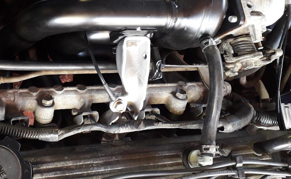
Neat and tidy.
Re-installed the injectors and rail with new rubber isolators in the head and new spacers on the injectors. Even though the current O-rings were fine after a visual inspection, I called Toyota about replacements and they casually informed me that they were £7........each. Thankfully the originals were fine to re-use.
-
19 minutes ago, burty said:
Sorry to hear this about the build mate
But it's still a fantastic little car in NA form and yours looks great so what's the plans now ?
Thanks mate.
I'd already completed the suspension and brake upgrades so that part is sorted and a massive improvement over stock, to be honest the test drive on leaky shocks and poor quality mix match tyres almost put me off buying it!
I'll be keeping it N/A for the time being and enjoying the work I've already put into it. With the corolla manifold it should be at 85 bhp and in an 850kg car that puts it at 100bhp/tonne, warm hatch territory but I remember my mates 106 rallye was still a hoot at about the same power level.
Not sure on the future plans when funds allow. At least its kept me busy during lockdown.
How's the body work coming on yours?
-
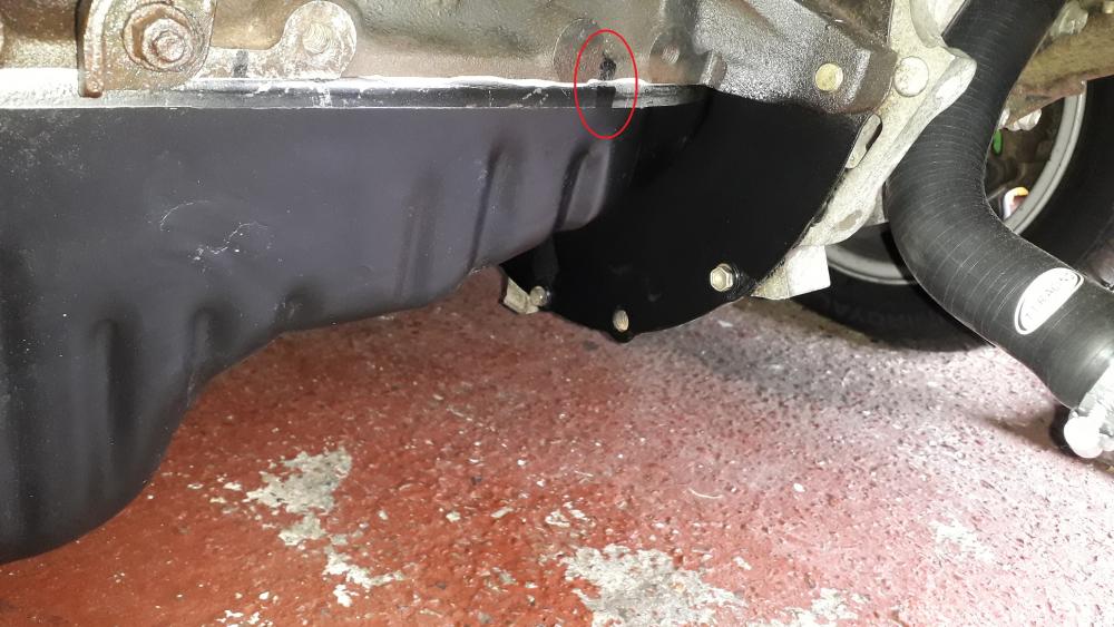
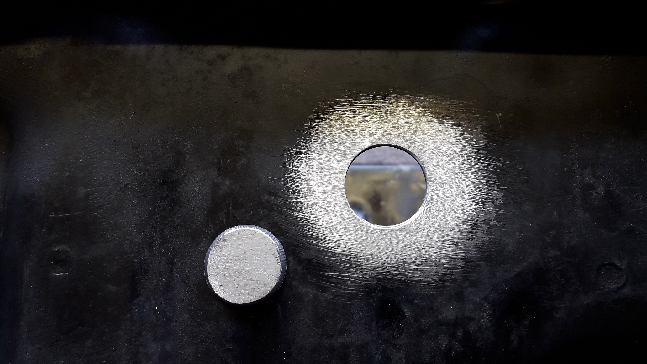
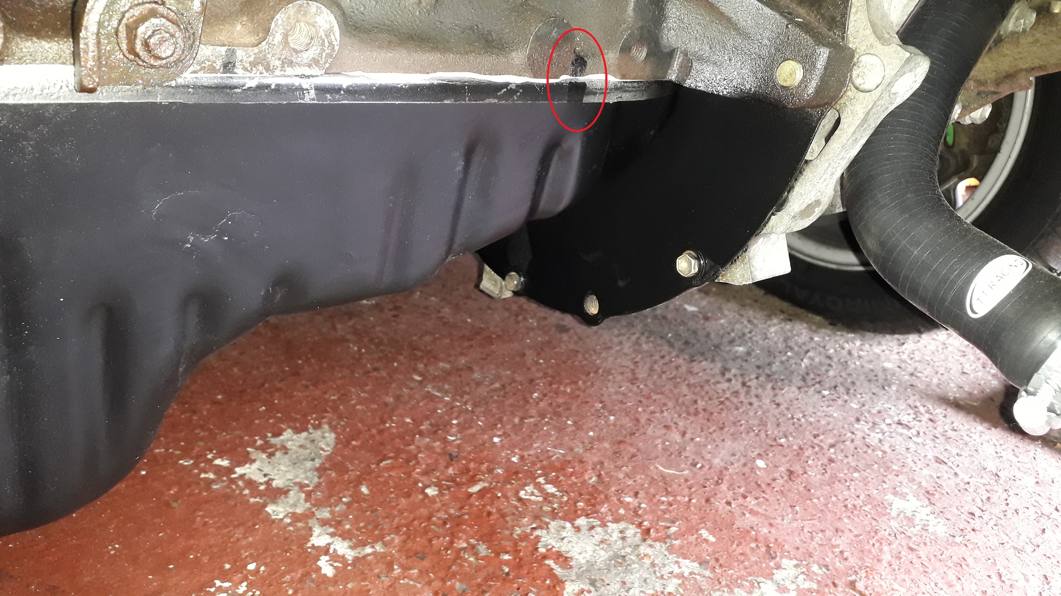
Well, after removing and replacing the thermo water outlet, I needed to remove the sump and oil drain so I could weld up the hole. I can confirm that Elring dirko HT selant I used on the sump is VERY effective as a bonding agent! I had to use a heat gun on the highest setting to break down the loctite on the bolt through oil return fitting thread as it wouldn't budge without.
Made a small steel disc of the same size and thickness as the sump material and welded the hole up.
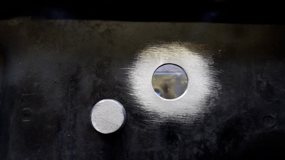
So... sump welded and painted it was reinstalled with Elring dirko HT sealant, I marked the position of one of the bolt holes on the pan lip and the threaded hole in the block is visible so it can be aligned before pressing the pan and sealant home. Once I'd hooked it over the oil pickup, I raised the pan up keeping it horizontal, slipped the flywheel end into the cover pocket, lined up the marks and pressed the pan home, tightened the bolts to 8NM in a zig zag pattern.
Painted the clutch cover while I was down there, No leaks from the oil pan so
One thing I will mention was even though it only has 43k miles on the engine, when I changed the oil the first time it went quite black after the first drive and this was simply from diluting the sludge in the pan with clean oil. There was a decent amount of black sludge in the bottom of the pan the first time I took it off (approx 10mm deep). Removing the pan allowed me to cleanout the sludge (and reseal the slight weep it had) and the current oil is still a clear, golden colour as it should be after the first 100 miles or so.
-
On 6/8/2021 at 11:31 AM, Dale SR said:
I know the feeling with money getting in the way of starlet plans! Needs must though eh!
Not all bad, still alot of fun to he had in a non turbo starlet!
On 6/8/2021 at 11:59 AM, Sam44 said:oh so sorry to hear this, but you have done the responsible thing. i have got loads of turbo stuff here so when your ready drop me a message and I will sort you out. very cheap cheap.
hoping you and the family are well.
Thanks guys, things are looking up. Family and home life are ok now but money is still tight. Thanks for the positive comments.
-
Dear diary, what a day it's been........😪🤬
Unfortunately due to an unforeseen change in personal / financial circumstances I wasn't able to complete the turbo conversion of Nanza. Even with careful budgeting and planning sometimes life still manages to punch you in the balls!!!
Most of the vehicle specific turbo build parts have been removed and sold now. Some have appeared on builds on this very forum and some familiar usernames have also bought stuff aswell. It wasn't a surprise at how fast they sold due to the scarcity of the parts. Helped out financially so it is what it is.
Gutted, as I have invested alot of time in this project, but there are worse things in life.
Currently the car is back together, naturally aspirated and I'm out driving her again in the glorious sunshine. Things are looking up so that's a plus.
There are some more updates to the build thread coming, hope you're all doing well.
👍
-
7 minutes ago, richardc9052 said:
Yeah I bought the turbo like 2 years ago, covid hit, I didn't do much until recently. Found Matt's videos alright and it does go well. I have just bought another turbo though so I'll see which one I like more when it's running.
No build thread yet. I will throw one up at some point. Forged, ORC clutch, 1.5 way LSD and will be running on a Speeduino UA4C. All parts are spread out yet, nearly time to assemble. We did up the turbo kit, rad, mounted intercooler and made up the piping all in preparation.
Sounds awesome, looking forward to the progress.
-
1 hour ago, richardc9052 said:
That is a China Maxspeedingrods Td05 20g
Big girl!!!
Saw Nick Kamveer on Matt berry's youtube channel running a TD05 looked to do alright on the 4efe.
Have you got a build thread for it?


.jpg.876ef12efe815e2258a18a0d9a5d4d68.jpg)


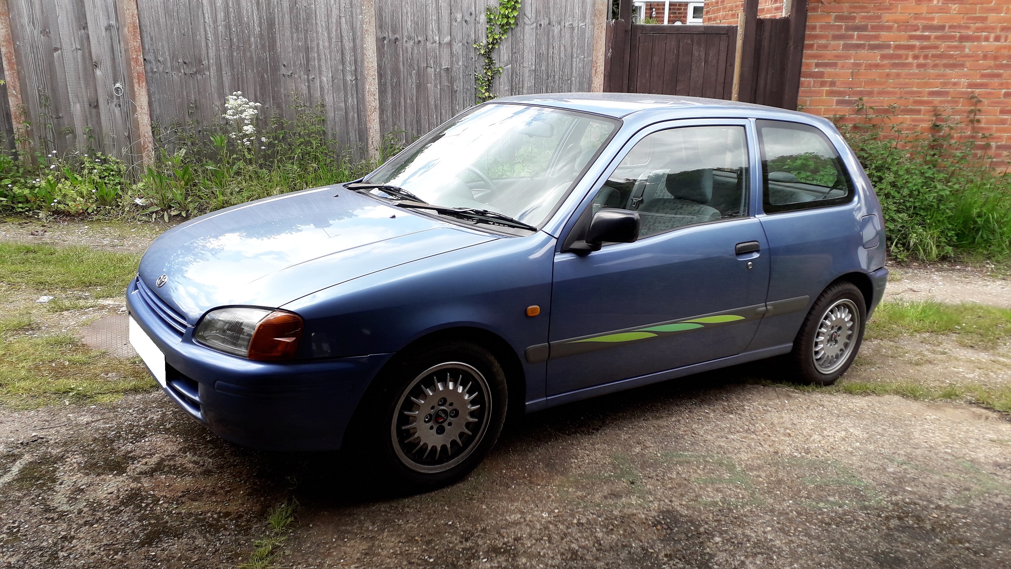
Claymore's sleeper 4efe+t-t+t build (R.I.P. the Nanza)
in EP91 Progress Blogs
Posted · Edited by Claymore
4efe Timing adjustment.
Bought a cheap Accuspark timing light to check and adjust the timing.
The instructions said to open the casing and check that none of the internals had become dislodged in transit. I removed the screws and opened the case to find this. As I have no idea what it should look like inside and there were no obvious breakages I reassembled it and moved on .
.
To adjust the timing you need to put the car into diagnostic mode by shorting the TE1 and E1 contacts in the diag. port with an opened out paper clip or wire. As I still have the original factory sticker under the bonnet 🧐, the settings and procedure are listed on it.
So after shorting the pins, attaching the timing light battery terminals, attaching the inductive loop to ht lead no.1 (note the direction of spark and point the arrow towards the spark plug) I started the engine. The timing marks on the pulley are a bit shit as the one closest the belt cover is hidden by the alternator belt and the second mark wasn't particularly easy to see so I stopped the engine, highlighted the pulley mark with Tippex and re-started the engine. The old paint marks on the distributor put the timing at 15 deg. btdc which is too much for the 10 deg +/-2 deg. (basically anywhere from 8-12 degrees btdc is acceptable). I set mine at 10 (ish.) by loosening the 2 x m 8 bolts and gently moving the distributor body to adjust until the pulley mark lined up with the 10 mark on the belt cover. Locked back into place. Engine off, paperclip out, timing light back in the box.
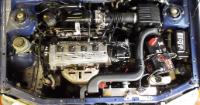
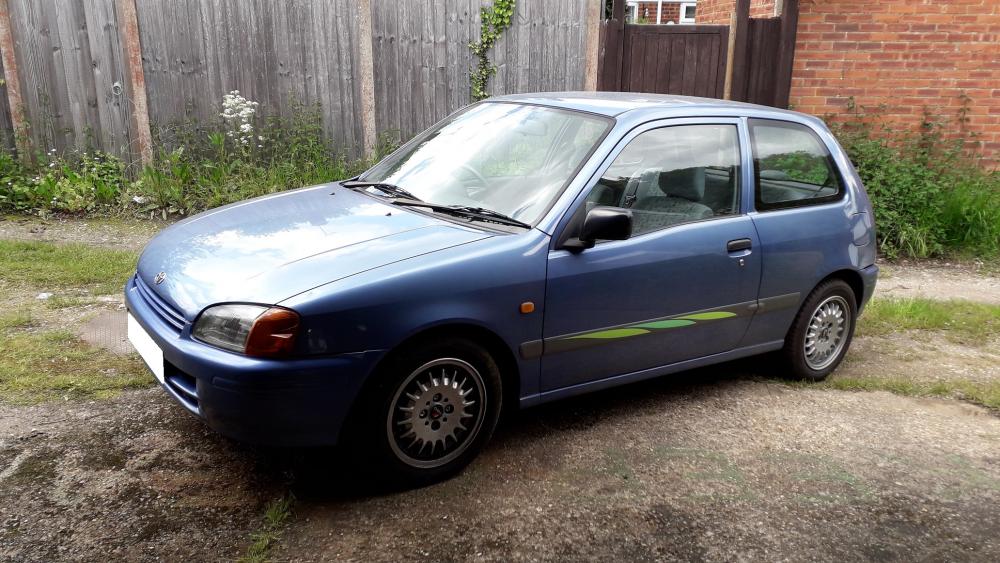
Gave the engine bay a quick detailing, not really my thing but neat and tidy is fine by me. Trying to keep it looking factory.
Added a can of injector cleaner to the tank (probably bollocks) and filled up with Super unleaded (pointless) and have been conducting the "Italian tune up" every chance I get.
Been out driving it for a few weeks now and the corolla inlet manifold has made an improvement. The low down torque has increased slightly and it is also more eager to pull to the redline where as before it became breathless quite quickly above 5k. It feels like a slightly larger capacity engine overall. I had also driven with the timing at 15 deg. and reducing it to 10 seems to have had a small improvement also (could be psychological) and the idle seems more stable since the timing change. There is also more noise from the PCV hose to manifold (a sort of rushing noise) that wasn't noticeable with the Starlet manifold. Still has the little growl from the intake resonator aswell .
.
Hiding