

Claymore
-
Content Count
660 -
Joined
-
Last visited
Content Type
Profiles
Forums
Wiki
Media Demo
Store
Calendar
Posts posted by Claymore
-
-
8 hours ago, Frankieflowers said:
We figure that out as well while swapping. There weren’t extra wires and extra connectors. I agree that there is some confusion in the manuals and in the echo pinouts. We could have saved precious time but we knew that we were pioneering a swap that only a few people there then they apparently went silent.
@Sam44 in one of his first descriptions he made for me mentioned keeping the Corolla 4EFE inlet throttle that in his opinion is more efficient. Again at it was a big amount of work we kept these upgrades for the future coming. So now is the time to understand what can make the engine better. Reading this thread that I have seen before I understand better that there are some defects that can be fixed. It’s just a matter of doing it properly.
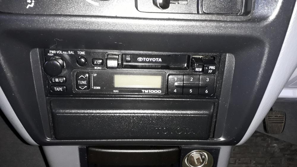
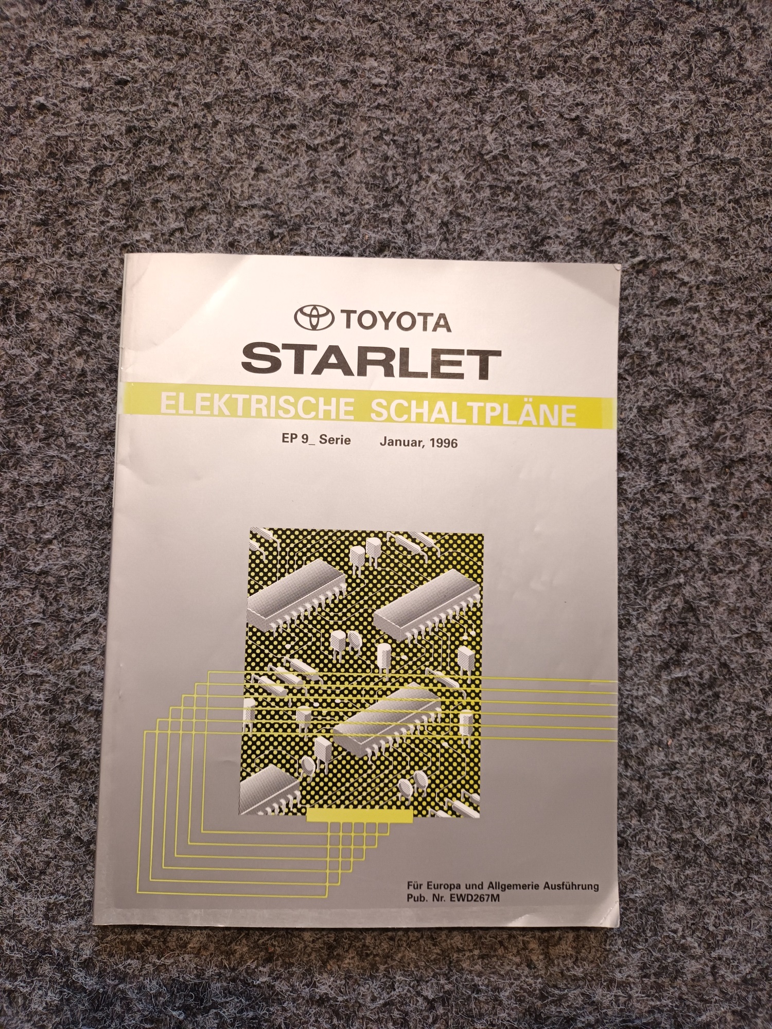
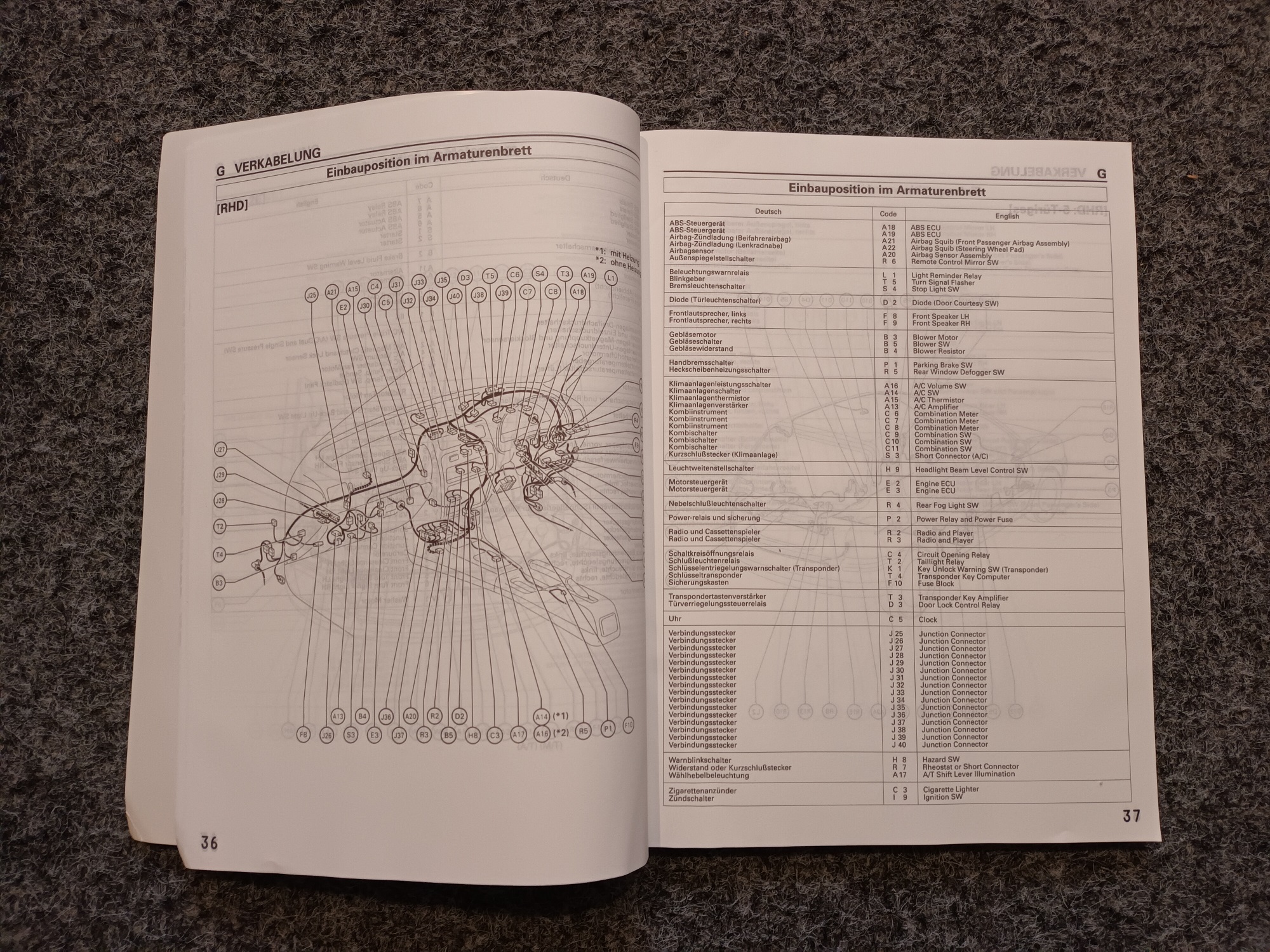
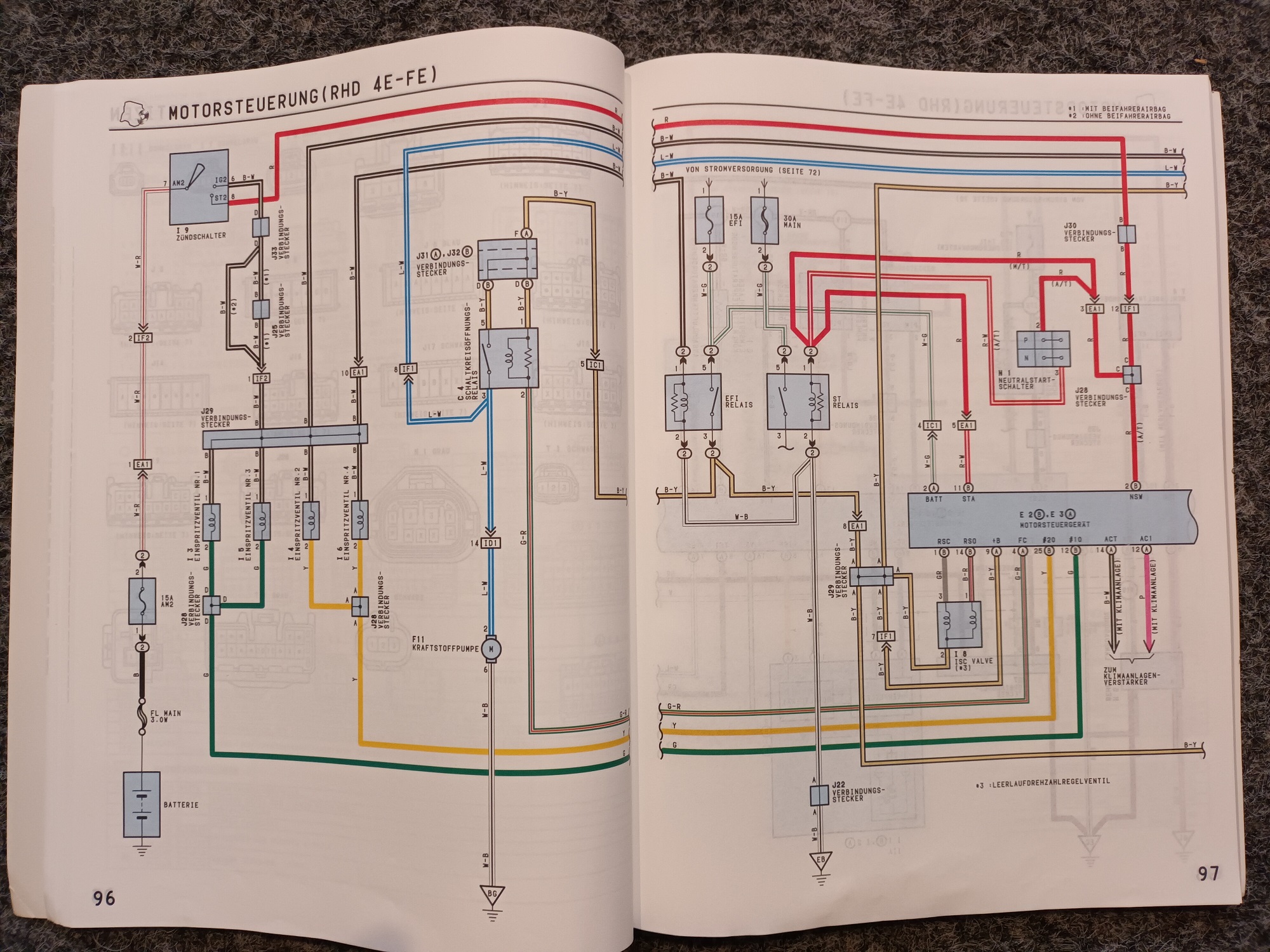
Know what you mean, I managed to get a copy of the Toyota electric manual for the 96/97 EP91 European models, has helped me a lot.

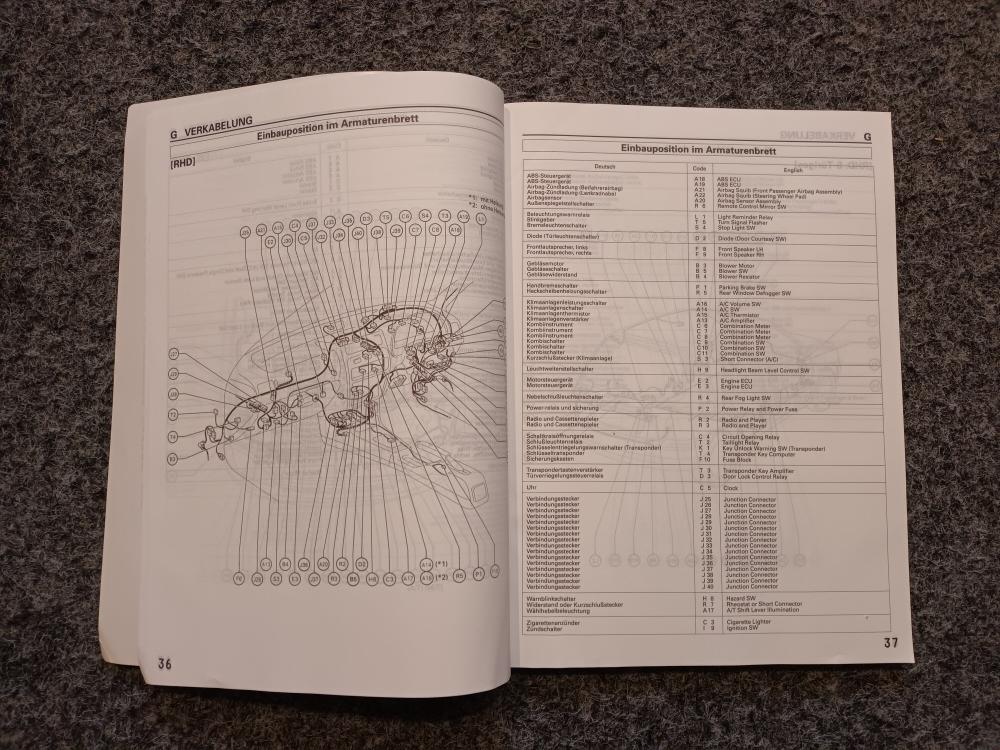
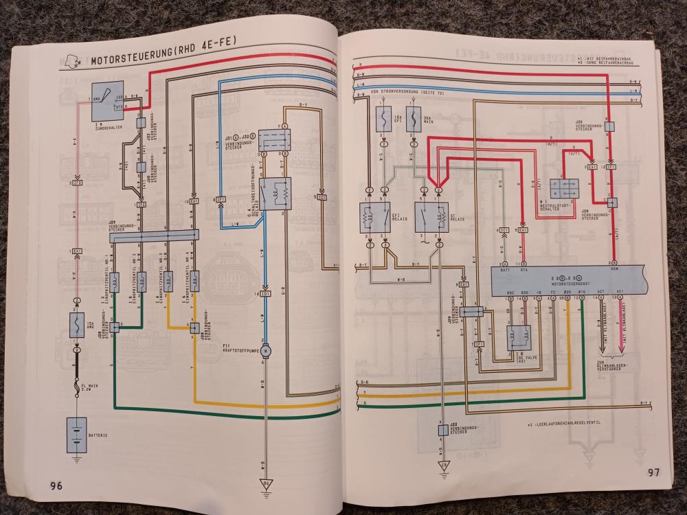
Different wiring to the 98/99 apparently and the JDM models had different colours also! Thanks Toyota

I think Sam was talking about the Throttle position sensor being better (variable, potentiometer) on the 4efe corolla compared to the 4efte MANUAL TPS (switch type). Your engine is a 4efte AUTOMATIC and this has the better TPS (variable, potentiometer) so don't change the throttle body as you already have the "good" one. Think it was covered in your first thread (page 10 and 11).
-
22 hours ago, Claymore said:
......... Check for leaks from hose clamps, intake manifold ports, Dump valve can leak (remove and block the pipes, go for drive to check), check intercooler for cracks etc. Some people do a "smoke test" to see if there are any leaks in the intake system........
Think I did ok then! 😜.
Glad you got it sorted Frankie. Now the modifying can begin.
-
4 hours ago, Frankieflowers said:
Which custom manifold do you suggest to buy?
The standard 4efte exhaust manifold can be ported by grinding / porting out the restrictions, I did it to one for my build. It will help prevent problems for a small boost increase but not the best option. I also know you don't like to modify rare Toyota parts 😉 (which is fine
)
The CT9 Tubular manifold Tuning Developments sells seems ok as the first upgrade, Hopefully someone using one will comment on its fit and function.
If you want the top level then WEPR make excellent products. But not sure how they will fit in a corolla engine swap vehicle.
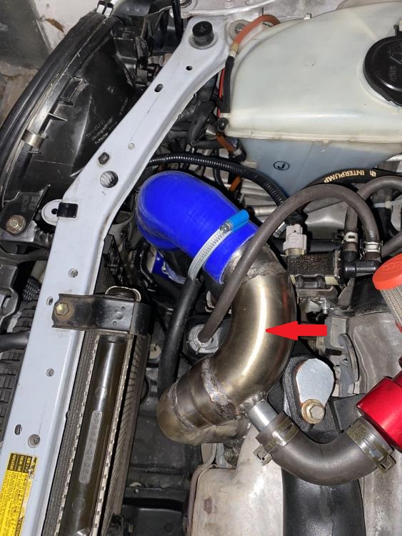
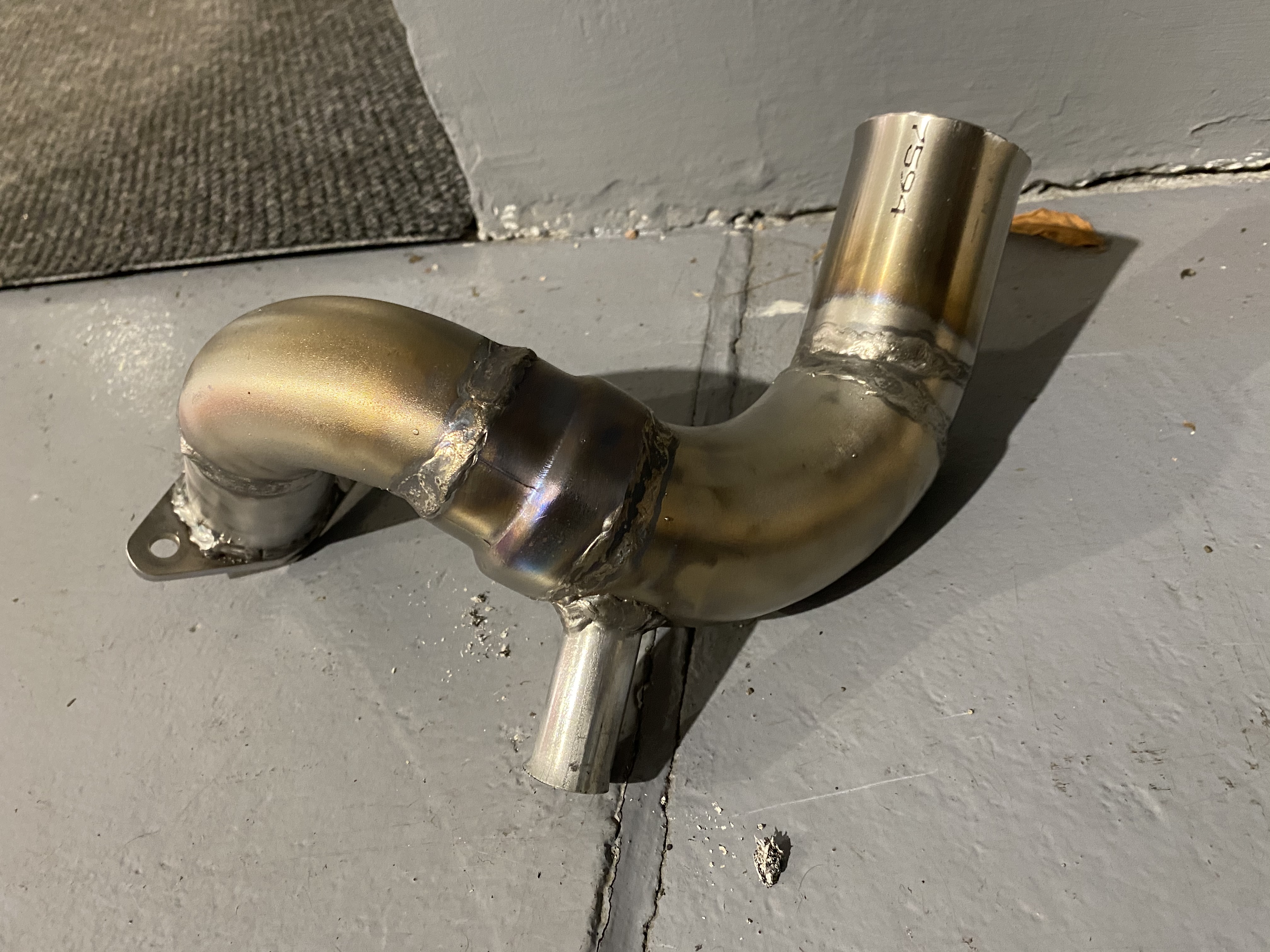
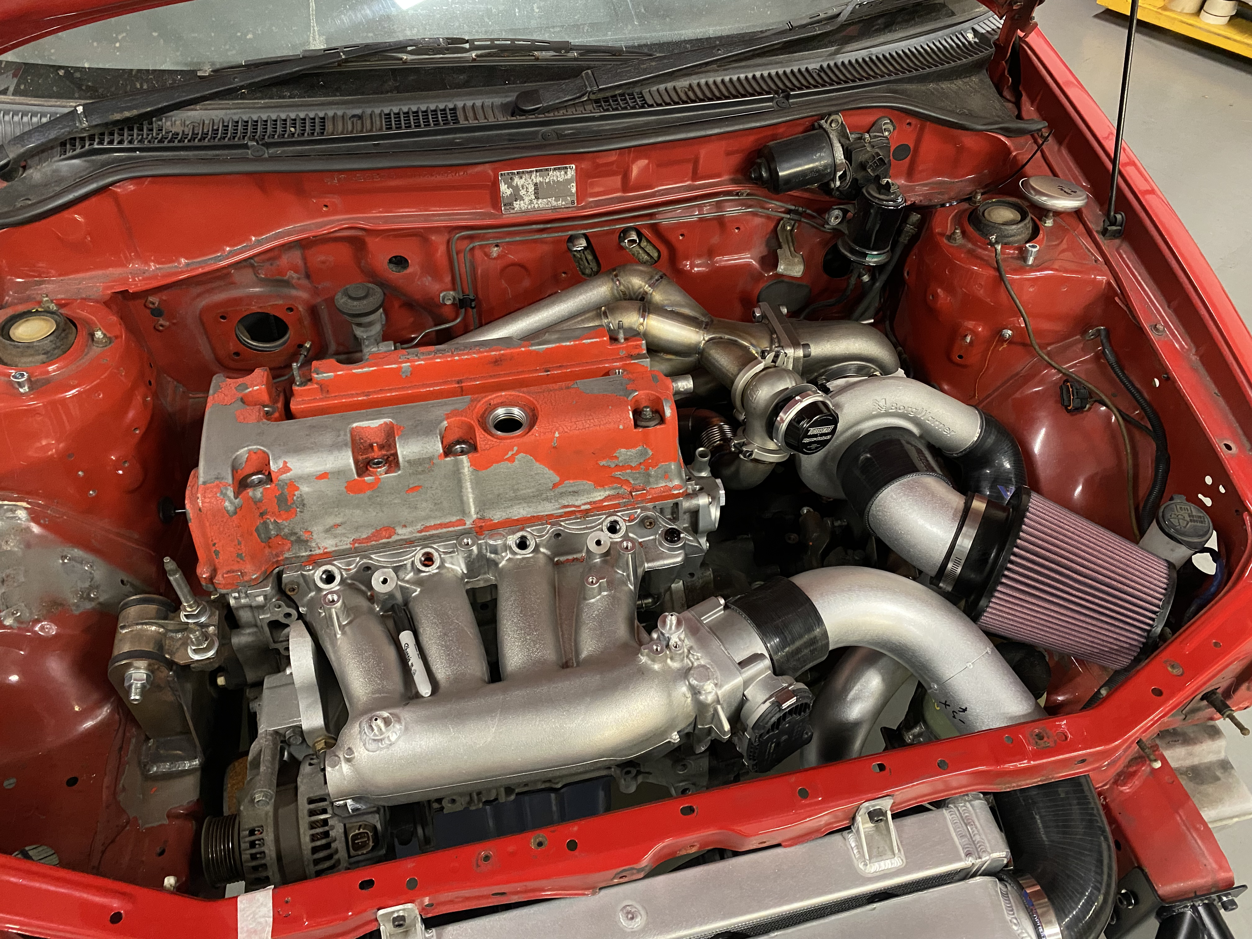
4 hours ago, Frankieflowers said:You pointed an arrow on our custom hot pipe. What do you have to say about it?? It does exactly what the other half pipes I’ve seen do. Thanks
This pipe is where I would weld the fitting for the second boost gauge hose to measure pressure before the intercooler.
-
12 hours ago, Frankieflowers said:
Where do I connect the boost gauge? Which pipe?
thanks for your comments. I am trying to figure out why I had a drastic drop of power. Everyone wrote that with a decent bigger intercooler and correct pipes I would have a 15% gain of power especially in the mid range with the original CT9 turbo without mapping. The turbo lag it’s quite important now and I lost the power that would make driving exciting. So it is obvious that if I change the turbo or get this one refurbished and wider inside with the bigger rotator (if that is the name) and obviously a brand new Achoo and map I will have power. That is in my project but we are talking about €1500. I was hoping that with the money I just spent I would have a good feeling and at least the same power.
The first thing to do before changing turbo (we call the larger compressor wheel install a "hybrid turbo") and ecu, fuel pressure reg, is to find the problem you now have.
Firstly, what did you change on the car before the problem occurred? Not being rude but it is always the first thing to check and if it was only the intercooler and pipe work then that is where to look. Check for leaks from hose clamps, intake manifold ports, Dump valve can leak (remove and block the pipes, go for drive to check), check intercooler for cracks etc. Some people do a "smoke test" to see if there are any leaks in the intake system. Also might be worth doing a compression test. Could remove the exhaust pipe from the turbo and check the wastegate port hasn't cracked too.
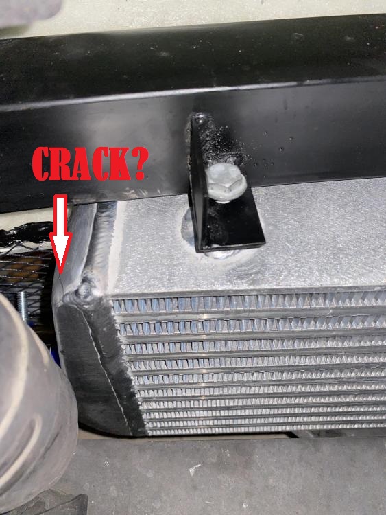
If the intercooler is oversized it would add a delay before the boost reached its requested pressure, but it should still get to the desired pressure. If the intercooler is too small / restrictive it will restrict the flow of air and cause a pressure drop preventing the boost reaching its correct pressure. What size core did you buy?
If you want to test the pressure drop you need a second boost gauge. First install both on the intake manifold port and compare the readings. The gauges should read the same. Then leave one attached to intake manifold and add the other to a port on the hose as close to the turbo outlet as possible (red arrow pipe). Then compare the boost readings when at full throttle / boost. If you want to only test the intercooler drop (not pipework as well) you have to install the gauge fittings in the intercooler end tanks, but this is extreme and unnecessary. I would talk to your tuner and see if he can help, they do this sort of stuff all the time, would be a lot safer and easier to control on a dyno. If you still have the bigger intercooler, you could swap it at the dyno and do a power run to compare.
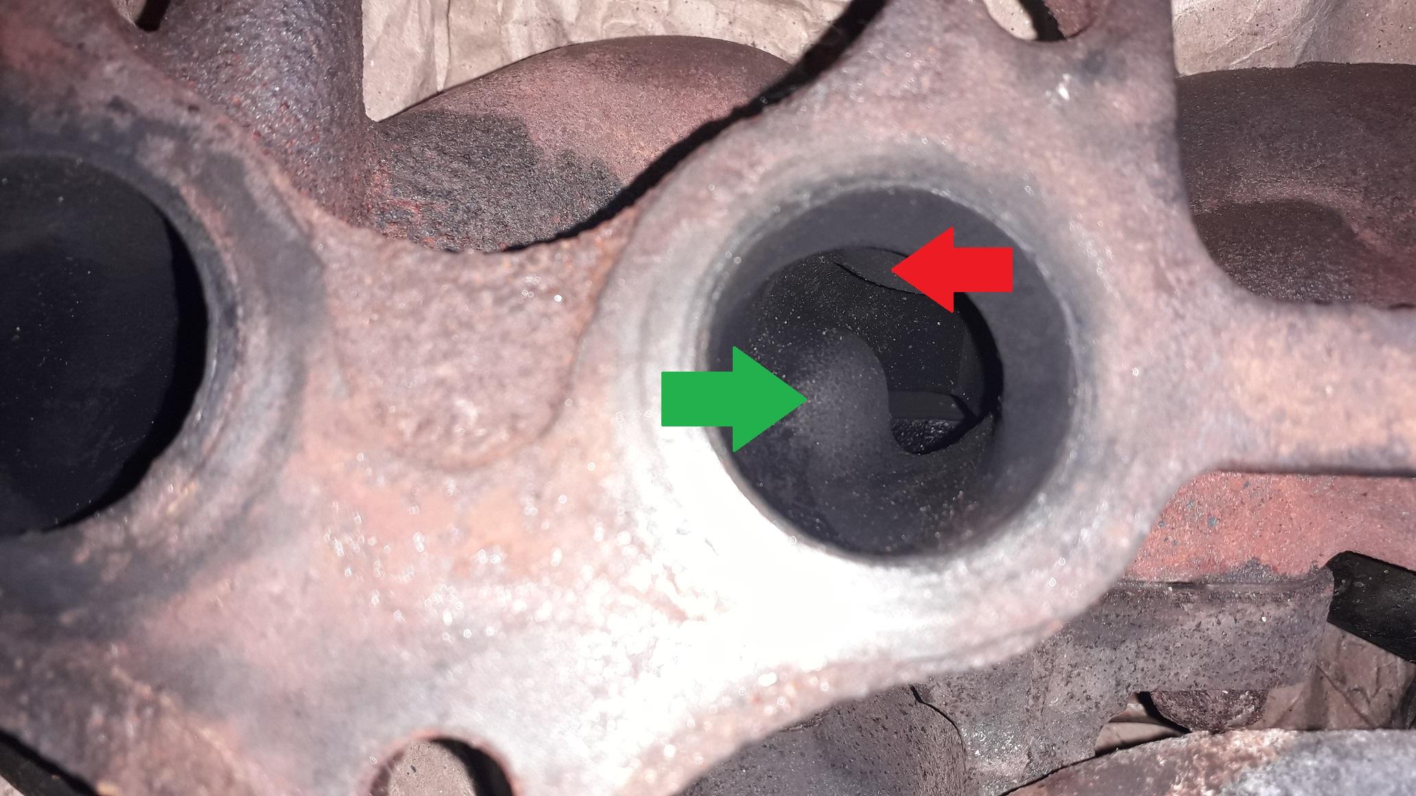
One other thing I will say is that the stock 4efte exhaust manifold has a quite bad restriction (green arrow bad, red arrow ok) in the no.3 runner (and some restrictions in 1,2,4 as well), most people don't recommend running high boost levels with the manifold as it can cause piston ring land damage.

-
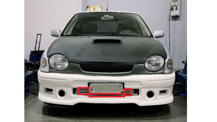
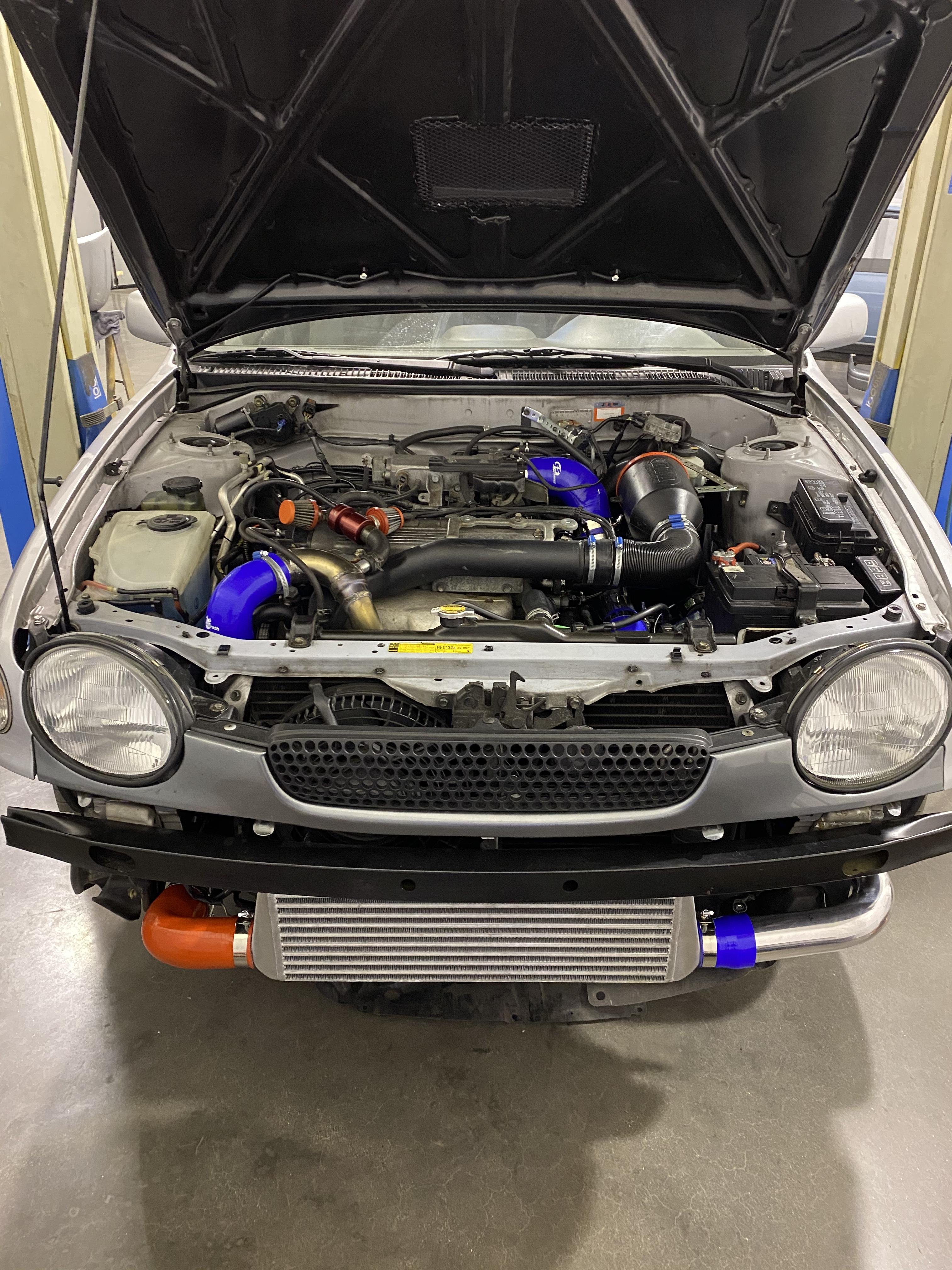
Its also worth mentioning that about half of the intercooler core is covered up by the bumper and licence plate.
Intercoolers need to have air passing through them to cool the charge air efficiently, it would help if the bumper could be trimmed but I understand if you want to leave it as it is. Or drill a line of holes below the intercooler slot. I don't think there is room for ducting, could blank off the gaps either side to help funnel air into the core.
*Edit* If you want to check the pressure drop from the intercooler you can measure it by adding a second boost gauge taking its signal from before the intercooler. You can then compare the two gauge readings to see the pressure drop.
-
On 7/15/2021 at 10:15 AM, candy_red said:
WIll you be running AC?
If not then a sandwich plate is the best and cleanest solution. Just grab one and grind away the material needed to clear the power steering tensioner bracket.
I have my old one that i used before adding the oil cooler and filter relocation, i can snap some pics for you to see what it looked like when i get home.
Frankie wants the solution to work with A/C, he has already tried a sandwich plate which he ground down and it leaked.
If the temp. won't work in a remote adapter fair enough, thanks for saying.
Hopefully the D1 adapter will work with A/C and no grinding of the adjuster bracket.
This may be too demanding for the space available and the restriction of "no grinding". Was fun to think about though.
-
Had another crack at the puzzle last night:
Assuming the gauge sensors are 1/8" npt.
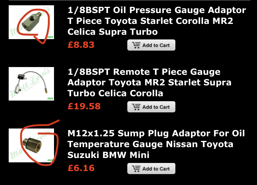
The simplest way I can make the MLR remote adapter work is shown below:

You need a 1/8" NPT adapter to screw into the MLR side port. It has to be long enough so the gauge temperature sensor in the end doesn't block the gauge pressure port in the side:
Not pretty, but it should work.
-
13 hours ago, Frankieflowers said:
We installed the front intercooler. Great job. As I tested it I immediately noticed that maximum boost went from 1 psi with the original setup to 0.9. Why? Apparently there are no air leaks socwhy is the engine so powerless compared to the previous setup?
Let me just confirm, originally you had 1 bar of boost and now you have 0.9 bar of boost?
Also the Glanza has a boost cut (overboost protection) built into the ecu at 0.8 or 0.85 bar which acts as a limiter. How are you producing more pressure than this? Maybe your gauge reads a bit wrong. The ct9 producing 1 bar will also be close to its limits as far as efficiencies go as well.
The most likely explanation is that the new intercooler has a higher pressure drop because it is longer / more resistant turbulators than the original Toyota one. The benefit is the charge air entering the engine should now be cooler / denser and give better performance that way. PSI is not the only thing that makes bhp.
What size intercooler core do you have?
-
15 hours ago, Frankieflowers said:
Great info. Can you confirm that this sandwich plate doesn’t touch the stearing pump bracket on the 4efte with air conditioning?
I was thinking to buy this adaptor with the pipe extension and pit the other two adaptors one in the other for the oil temp and pressure gauges.
Hi Frankie, I can't confirm if it fits the 4efte without touching the power steering bracket or air conditioning. I posted the dimensions so you can measure the engine you have to see if it fits. Dutchie has bought one and he can tell you for sure when he has test fitted it.
The bottom adapter in that picture fits into the oil pan drain hole and puts the temperature sensor under the car. The sensor is a bit closer to the road (can get hit on speed humps) than I would like.
15 hours ago, Frankieflowers said:This is what I’m talking about. Relocation metal pipe from the front right pressure OEM sensor and The other two adapters screwed one in the other with the two oil temp and pressure gouges in the side. I think this is the only way to work around the sandwich plate issue. Tell me what you think about it.
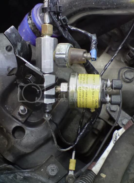
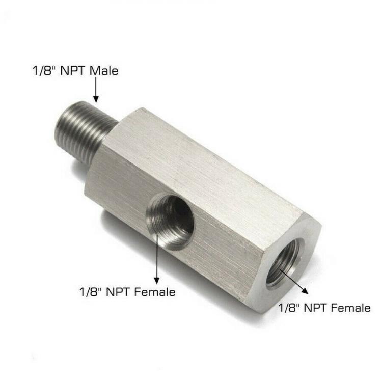
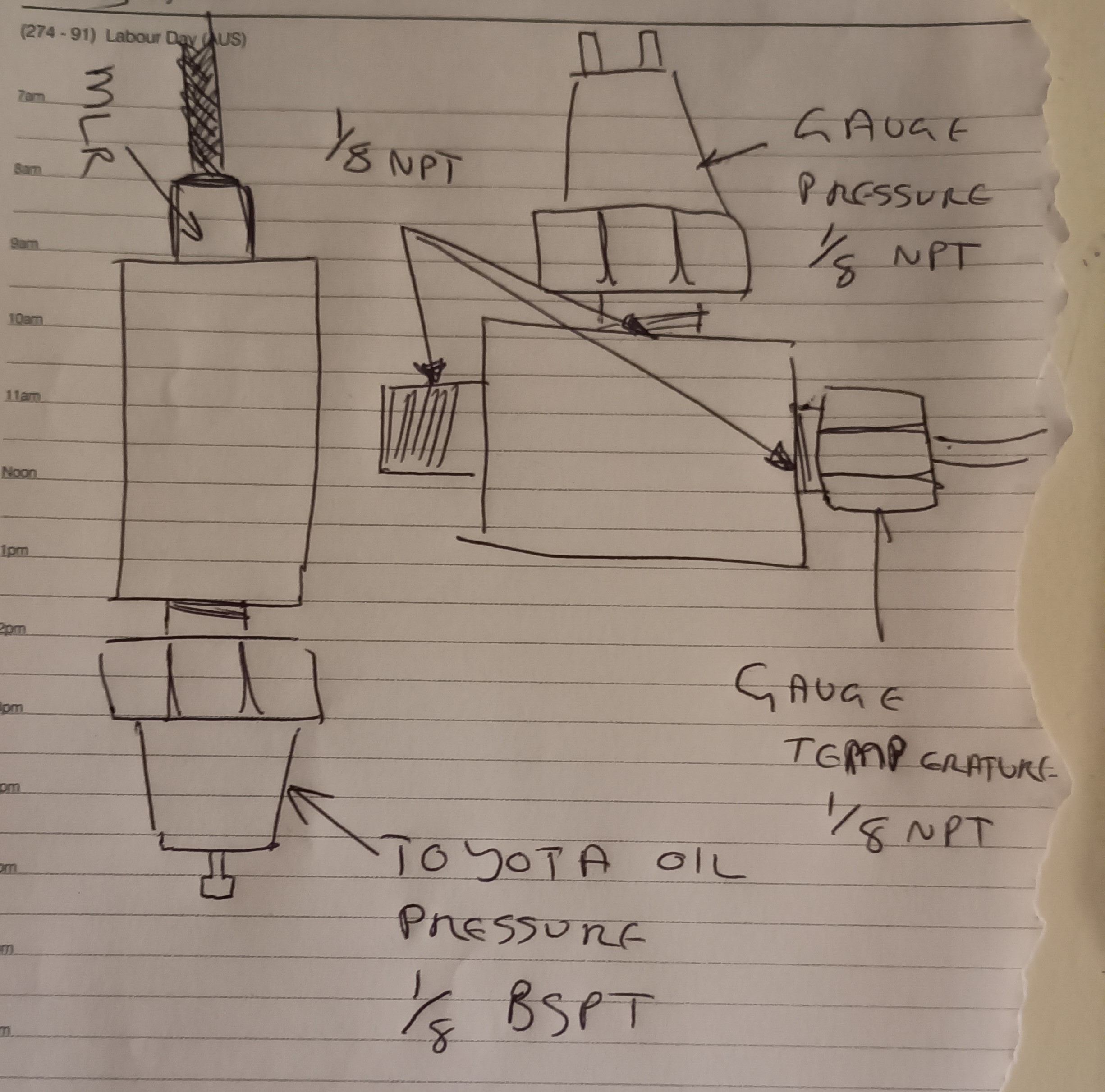
If you want to use the engine block oil pressure sensor port with the MLR adapter shown in the picture above, as far as I know it will have an 1/8bspt on the end and a 1/8npt on the side. The Toyota sensor is 1/8 bspt. The gauge sensors for temperature and pressure will be 1/8 npt. You have to think which sensor will fit in which hole because the temperature sensor needs extra depth and may not fit in the 1/8npt on the side, it may have to go in the end and then you will need 1/8bspt on the side for the Toyota pressure sensor!
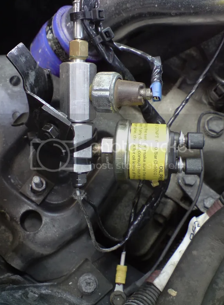
In the setup below the threads of the ports are different.
Red arrow = The original Toyota oil pressure sensor 1/8 bspt (on the side)
Green arrow = The gauge oil pressure sensor usually 1/8 npt (on the side)
Blue arrow = The gauge oil temperature sensor usually 1/8 npt (needs extra length so must fit in the end!)
Orange arrow = these male and female threads must match.
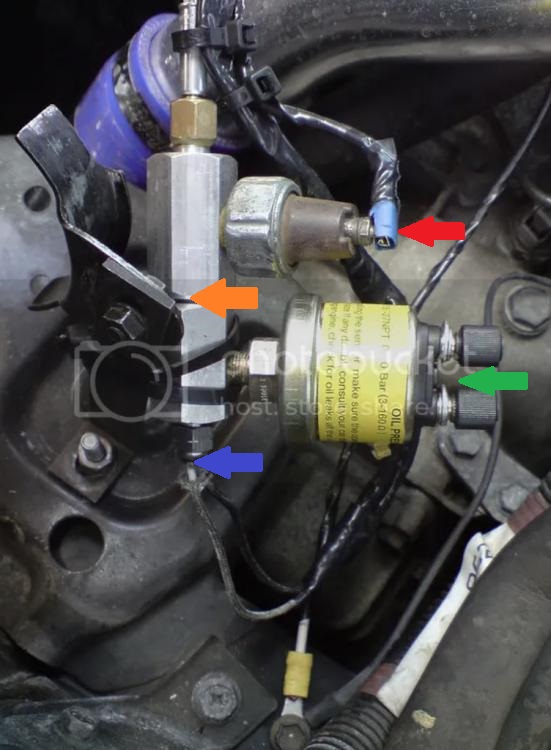
You need to check which sensor threads you have and where they must fit on the adapter (side or end) and then you can choose the correct adapters.
It would be easier to copy akayakpotter's setup with the Toyota pressure sensor and gauge pressure sensor on the remote hose adapter from MLR. Then the oil temperature sensor in the oil filter relocation port with the adapter if there is room without restricting oil flow. James G also has the temperature sensor in the oil filter relocation port.
-
On 7/15/2021 at 6:44 PM, RoyalDutchie said:
Thanks, I've got a adapter with the stri gauge set, but no idea if it is the correct one, the pitch seems fine and the socket for its is 17. Stri also doesn't mention it in the manual😅
Maybe something like this would be usable depending on the space around the pressure switch. Did some searching a while back though a Y-adapter has been used successfully.

I've had a look on the 4efe I have and there isn't a huge amount of space to fit this type of adapter and then the Toyota sensor in the end as the sensor or wiring plug may hit the clutch slave pipe. Also the wiring plug may not reach the sensor:
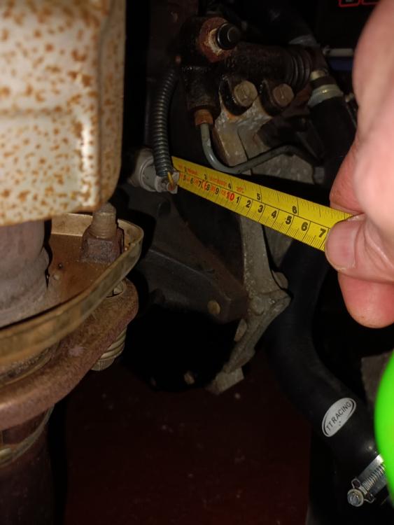
The adapter with hose that akayakpotter suggested will be fine as it relocates the adapter at the end of a hose.
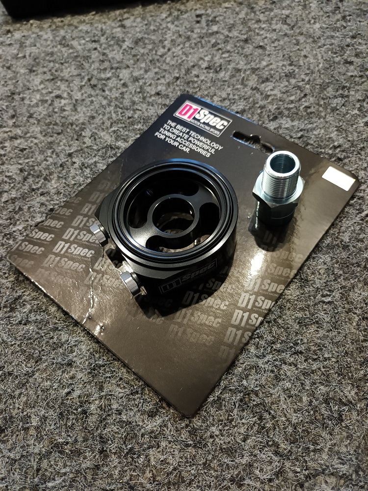
Or there is an oil filter sandwich plate (D1 spec) that may fit without modding the power steering pump bracket.
3/4" UNF 16 tpi thread.

Outer diameter of housing = 74mm,
Inner diameter of housing = 54mm,
Housing thickness (not including O-ring) = 28mm,
O-ring seal outer diameter = 68mm,
O-ring seal inner diameter = 60mm.

-
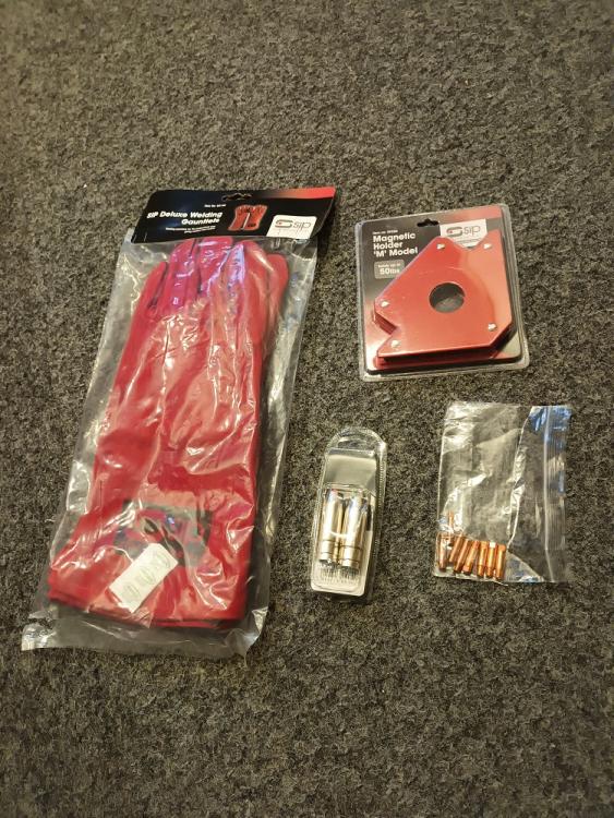
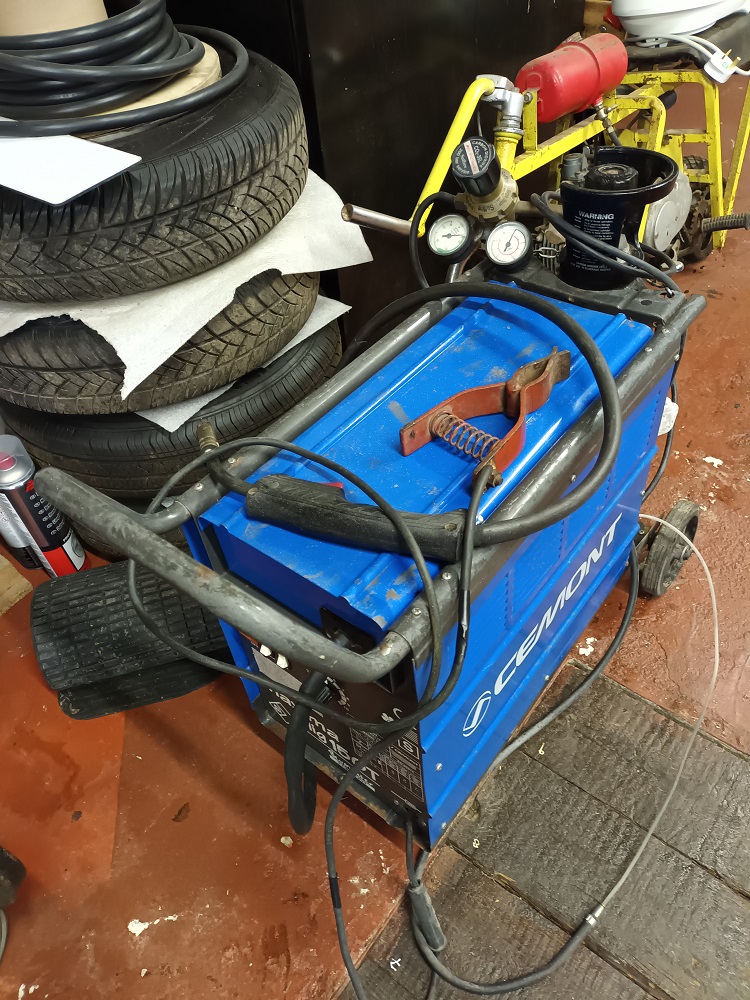
Xmas update, managed to buy a Mig welder off a friend as he had upgraded his. Needed a clean but otherwise good condition and I've used it in the past so I know it welded fine.

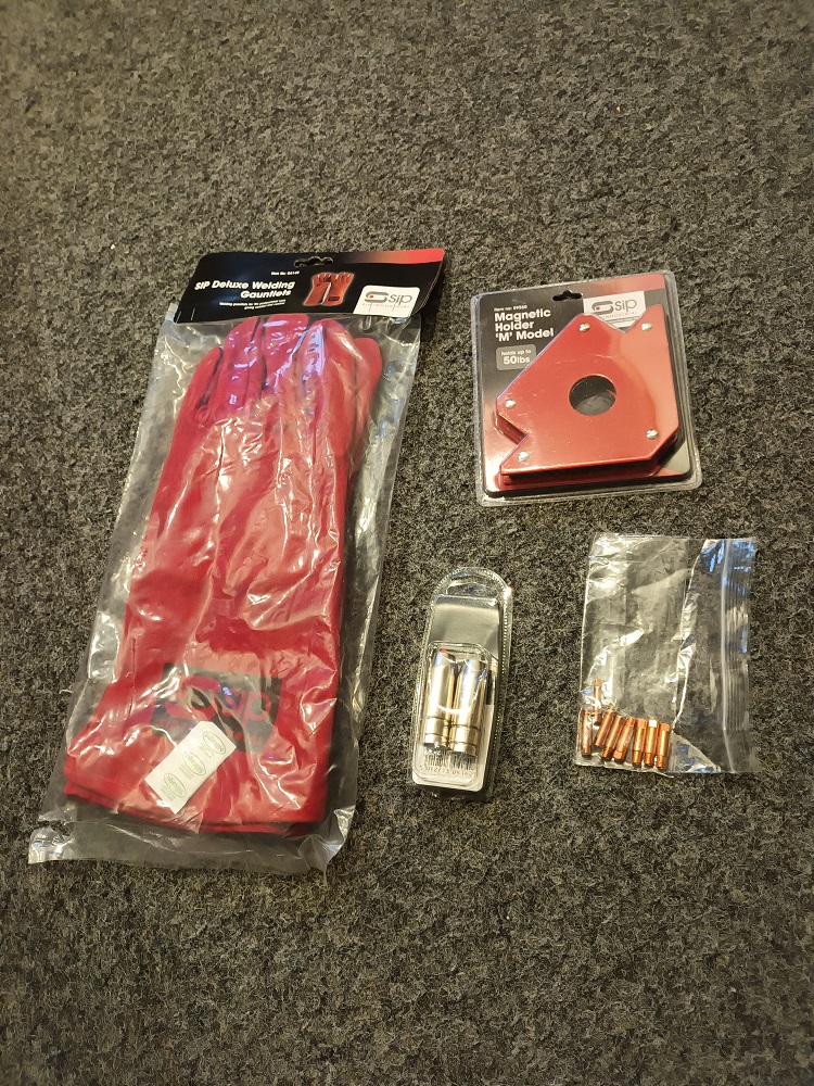
Also needed a few accessories to bring it up to snuff, new tips, gas shroud, earth clamp. Also needed gloves; a magnetic square is always useful.
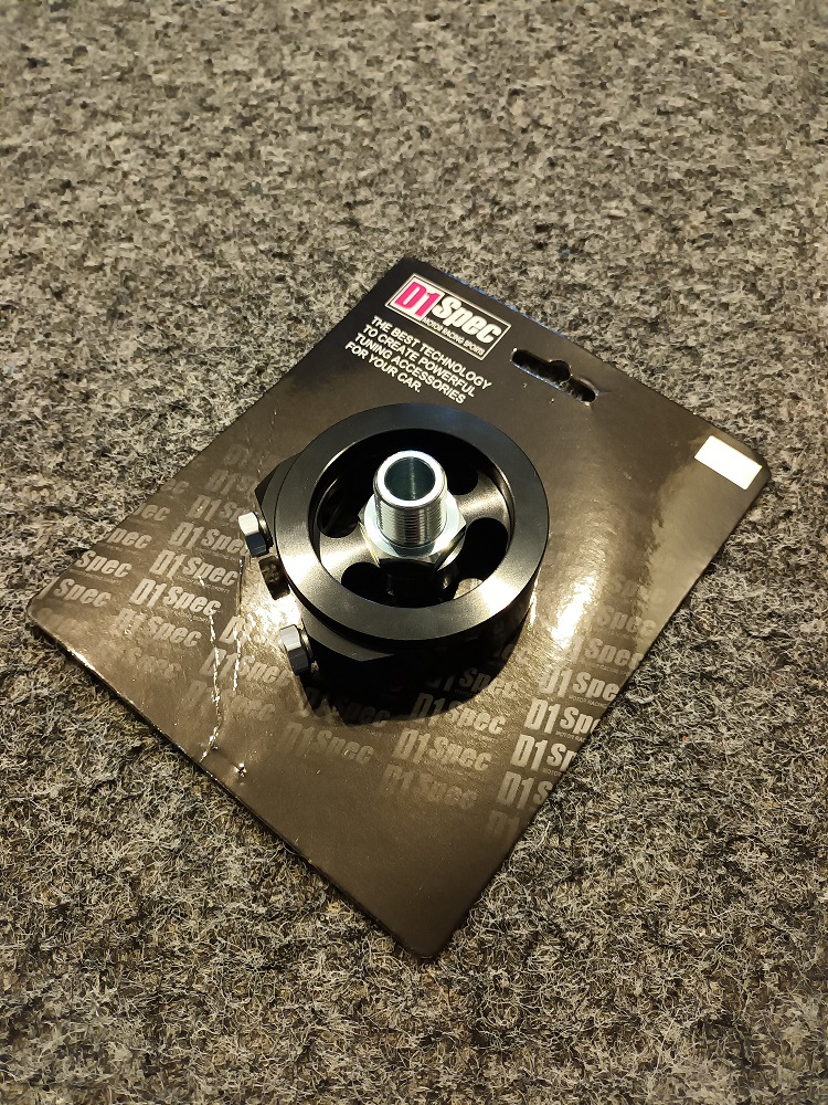
Also got a D1 spec oil filter sandwich plate (I see you on the other forum!
 ) and thought I'd measure it up for anyone interested in the sizes. 3/4" UNF 16 tpi thread. It's very nicely made as well. Need to check how well a filter mates to it as they are a universal product.
Outer diameter of housing = 74mm,
Inner diameter of housing = 54mm,
Housing thickness (not including O-ring) = 28mm,
O-ring seal outer diameter = 68mm,
O-ring seal inner diameter = 60mm.
-
1 hour ago, Starletson said:
Merry Christmas to me, wheels powder coated, back to oem. Interior in, just need door cards. Hope everyone has a great Christmas 🎄
Good work, merry xmas dude.

-
14 hours ago, CallumWellens33 said:
Unfortunately I didn't mesure it mate. I'm going to do rocker seals soon so I could take it back out to measure no bother.
As for clearances, I knew it was a thing, but installed it on my own. It was only when I asked my boss that I realised I needed to do something about it. So when the rocker gasket kit arrives, he's going to help me have a mess. As I'm sure you can understand, being an apprentice in the modern automotive industry, everything is 90% electrical so it takes someone like my boss to set me straight. Its all about learning I suppose. He also told me when fitting a second hand cam its good to use the caps the cam had before hand. As I didn't have these there's nothing I can do about it now. For anyone's benefits, the cam cap setting is 13nm.
As for the manifold, it 100% made a noticeable difference at around 3k for me. It seemed to pick up sharper. I'd say it's worth it for shear driveablity alone
Every day's a school day mate, we never stop learning.
Don't forget the forum is here to help if we know what your up to!
-
21 hours ago, CallumWellens33 said:
Would also like to thank@BMX-RIG for selling me a great priced glanza cam. Wouldn't hesitate to use again in the future.
It's installed and honestly makes a night and day differnece. Sam is a legend for putting me onto it, so thanks again Sam. If anyone N/A wants a great bang for bucks change, I'd recommend this.
Glanza inlet cam, measures 41.5mm. Picks up massively at 4k and honestly feels like it doesn't want to stop come 6.5k. Cannot recommend enough!!
Don't suppose you measured the base circle of the cam lobes? Trying to get confirmation it's 34mm for another thread.
Did you need many new shims or were you able to swap about the ones you had to get the clearances correct?
The only mod currently on mine is the rolla manifold and it improved low down torque, also has better pickup at the top end to limiter (no rev counter!) but it also feels like it has a rich/flat spot in the mid range that makes top end feel more pronounced. Need to check what cam mine has in it.
Any pics of the install?
-
The 4efe wiring for the instrument cluster is different, but the wires can be re-arranged in the plugs to work or use the correct clocks for the loom.
There may be more differences.
Not sure about the Glanza
-
9 hours ago, RobSR said:
Yup - fits!

Approved.
What size turbo are you running?
-
Looking forward to this Frankie, great work on the rear disc conversion as well.
Don't forget to copy and paste a link to the other thread. 😉
-
Nice to see another build thread starting. It looks great in black. 😍
-
4 hours ago, Sam44 said:
Getting the internals super polish finished has so many great benafits + my starlet box is really very quite after polishing. I'm very impressed with it.
After alot of research I'm using Volvo hgv gear oil. It's extremely durable. Does not seem to be affected by temps (great cold as well as hot), as well as extremely long long life. 100k oil changes.
transmission oil SAE80W-90, 97305
part number: 85116240
Just make sure you get the right oil classification for the box. Some of the results for SAE80W-90, 97305 show equivalent oils as GL-1 which isn't suitable. Is it suitable for LSD boxes? I know that helical and plate types differ.
I've always had good results from Redline products in non-lsd gearboxes if it helps.
3 hours ago, RobSR said:Trevstar has had his gears superfinished, might be able to help.
-
-
On 11/21/2021 at 8:03 PM, enots said:
**UPDATE 21/11/21**
Well tubbing the arches threw some problems/decisions to be made with the car. During welding because of the heat the filler on the arches cracked, I was expecting this which wasn't the issue the problem was once again down to the previous bodyshop who had done all the work. The rear arches had around an inch of filler on top of them which also followed up the whole of the rear quarters 🙄
Upon removing all of said filler I kept finding more and more problems. More rust, the original arch folded over against the new arches had started rusting the new ones, the original gt side trims had been screwed into the quarter panels with wood screws then just plastered with filler to hide them, and some awful welding also hidden by it all. Part of me at this point was thinking of selling up because I couldn't be bothered with even more work. But I've ordered a new arch for the one side and I'm going to buckle down and try and get it sorted over winter.
Few pics of the mess
This is how much filler/plastic/rot/woodscrews😂 was removed
Filler was literally slapped on everywhere
Going to aim to keep the shape of these metal arches as much as possible as they were blended in alot smoother before and I prefer the look of them like this! Busy few months for me ahead!
The previous bodyshop really did a number on that.
Well done for sticking with it, so much effort but it'll be worth it.
-
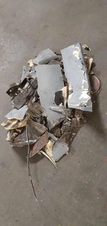
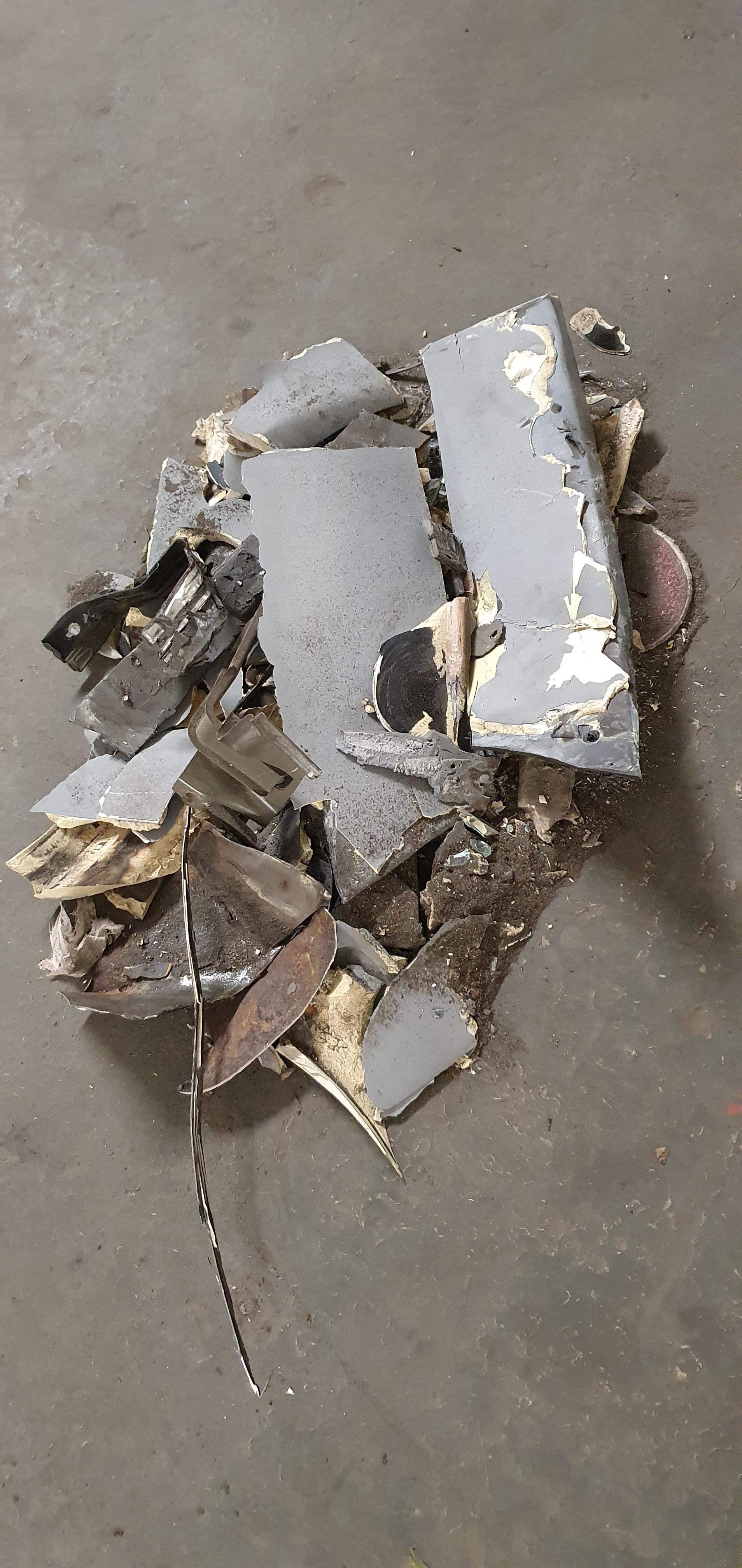
Looks like it got sold on and fragged:
https://www.ebay.co.uk/itm/175043054769?hash=item28c1610cb1:g:Po4AAOSwvClhpOe4
-
17 minutes ago, RoyalDutchie said:
The only thing left is checking if the core gets hot then. Seems the coolant may not be flowing through the complete core. Maybe the air flows past it instead of through the core? Not sure if that is even possible, but at this point should be considering every possibility.
This 👆
The heater core is just a small radiator inside the heater box/cabin. It should get as hot as the coolant is in the engine.
If the core is cold it is either blocked (or the feed pipes are?), incorrectly re-cored (hopefully they got it right!) or air locked.
If the core is hot as the engine coolant then its the heater box flaps not directing the core heat into the cabin correctly.
Start by checking if the core gets hot as Dutchie said.
-
Flash bastards 😡
This is what I have:


K20 Turbo EP91
in EP91 Progress Blogs
Posted
Looks like a pretty serious SKarlet build here!
Is the boost control cannister for wastegate dome pressure? As a replacement for the CO2 bottles drag racers use?
Also interested to see the results from the vertical flow intercooler.