


Frankieflowers
-
Content Count
416 -
Joined
-
Last visited
Content Type
Profiles
Forums
Wiki
Media Demo
Store
Calendar
Posts posted by Frankieflowers
-
-
On 7/28/2021 at 10:55 AM, Sam44 said:
charcoal
Can you link me a smaller version I can buy because the Corolla can is too big now. It’s actually full so I would put some thing lighter.
-
On 8/22/2021 at 5:36 PM, Sam44 said:
yes that is what that plug/pins do. looking great. well done.
is it running yet??.
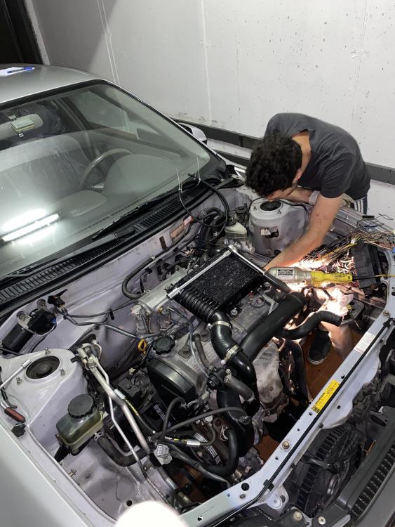
Sorry for the late reply. I am in Sardinia for work and Internet is very. So the engine is running well. We still have to connect the dashboard grounds because the RPM on the dashboard is not stable. There are two ground connections on the ECU that need to be connected properly in order to make the instruments work and avoid the risk to burn the ECU. As soon as I go back we will finish the job. The engine is running well. Of course we just did a first test before I left but we are happy that the mechanics are good and the main electric connections has been connected. We will obviously need to go deeper and step-by-step double check everything on the dashboard and ECU connections. I would love to put the switch on the dashboard to connect from low to high boost. Maybe you can tell me how to connect it?
-
On 8/8/2021 at 7:01 PM, Sam44 said:
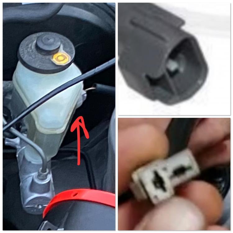
Sorry about late reply. The 2x pin connector grey in colour and not connected, is for your brake fluid level warning. It goes to your brake master cylinder fluid float.
Yeh the other valve is the high low boost solenoid. If you don't have the button for the dash to operate this valve then remove it and just run high boost. Other wise you might and will probably just be on low boost (fail safe mode).
-
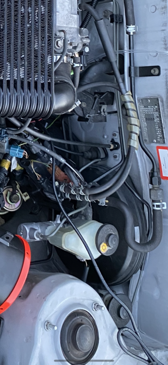
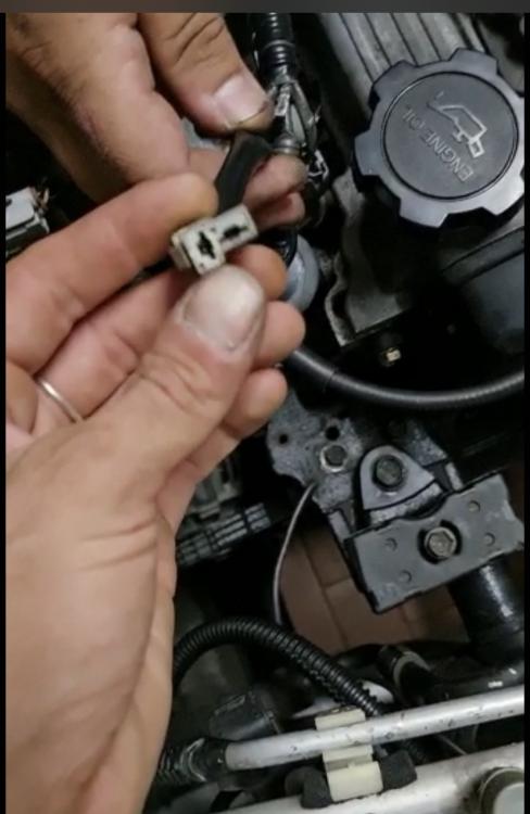
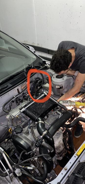
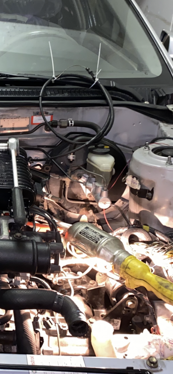
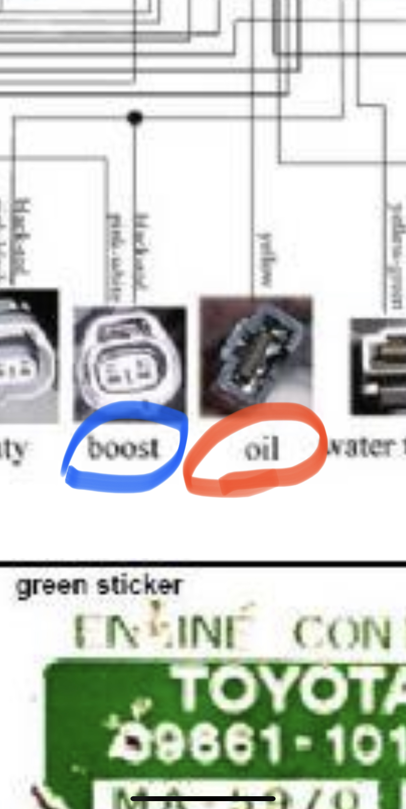
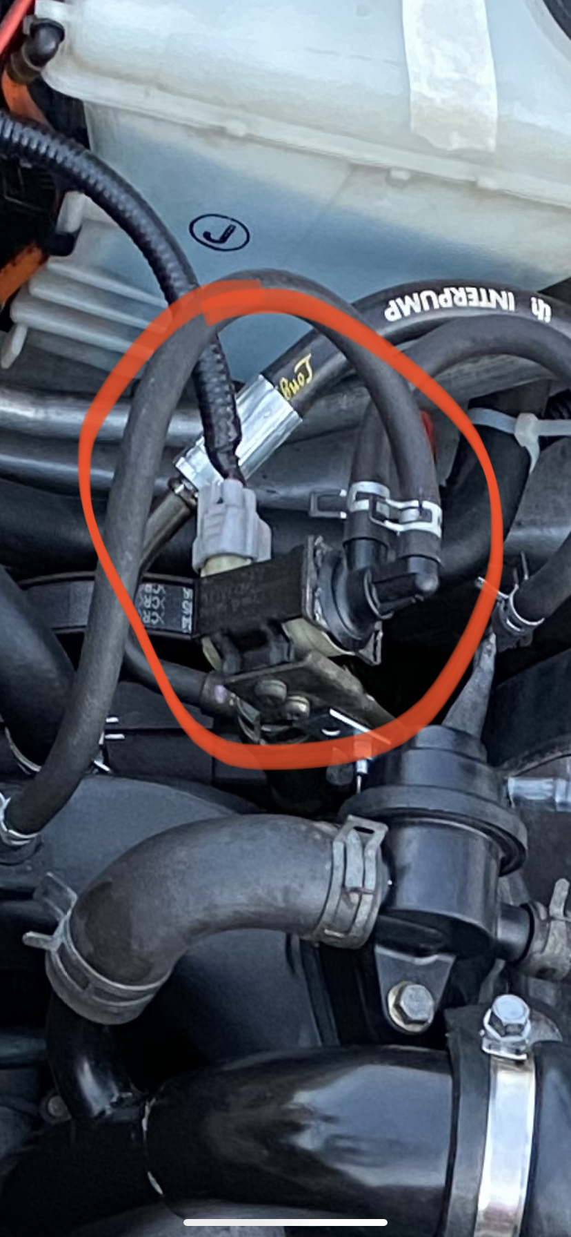
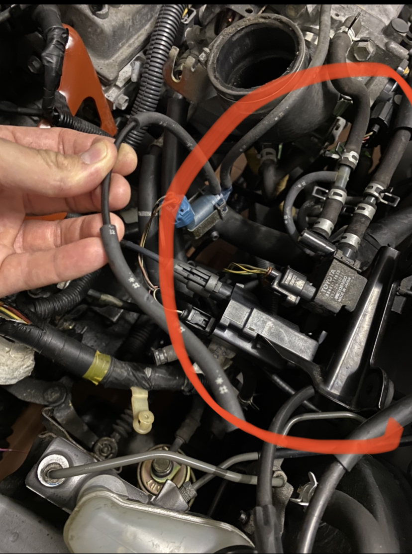
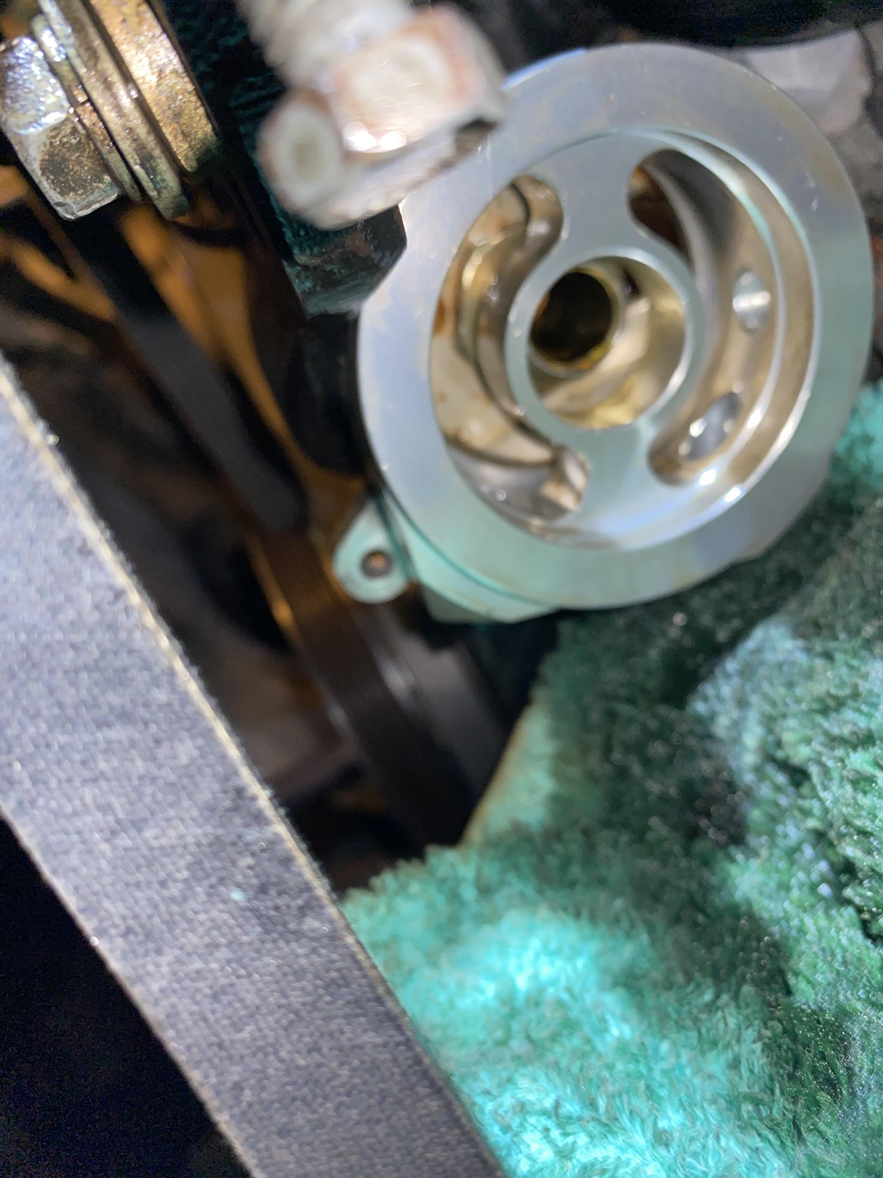
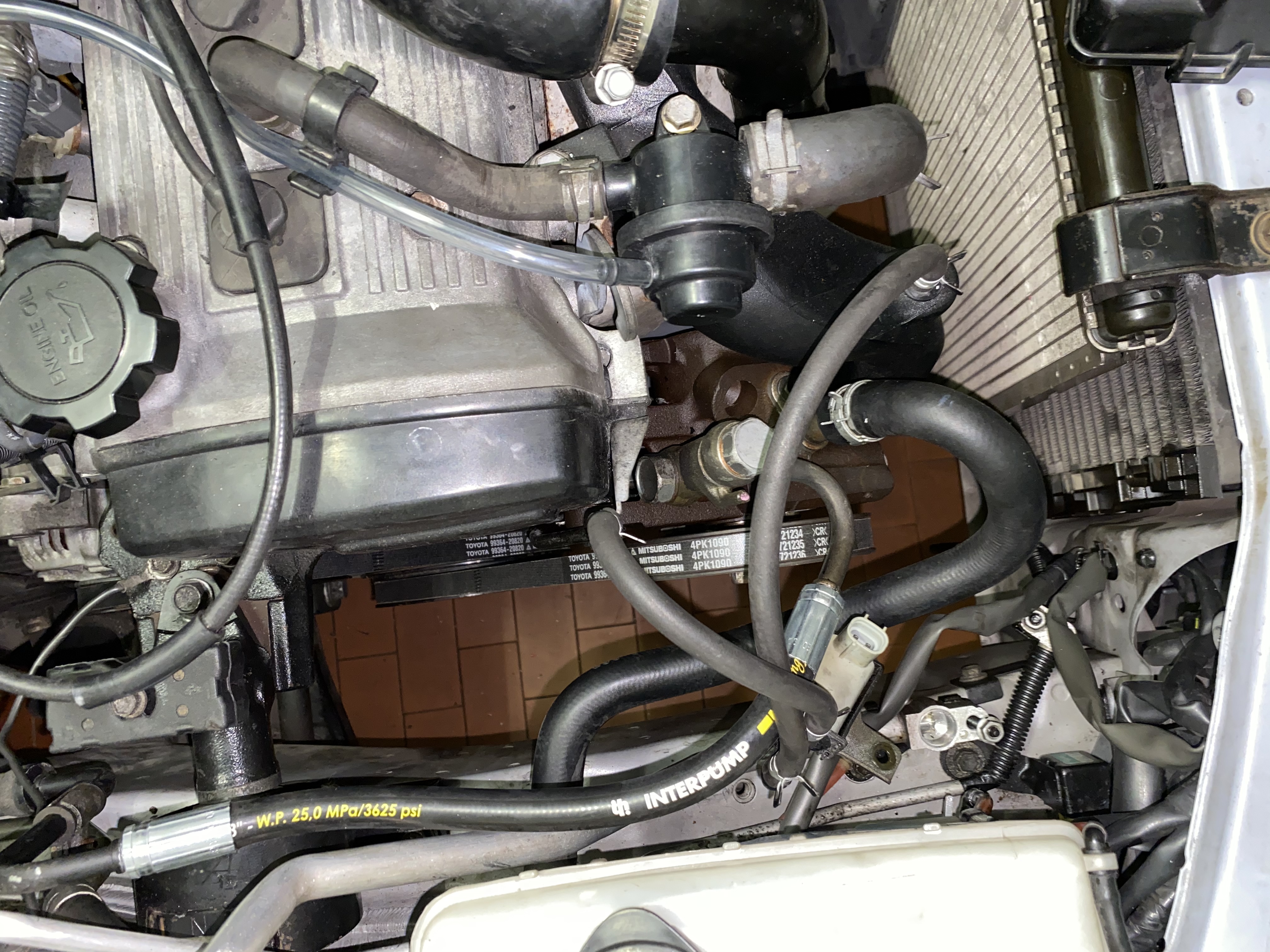
Here’s the connector I do not know. My friend was talking about boost control. If so then I don’t have the boost control valve. I thought lose control had the connector am showing below and it should be the vacuum on the left side of the engine in front connected to the turbo intercooler air output.


-
On 7/28/2021 at 10:55 AM, Sam44 said:
the filter should work.
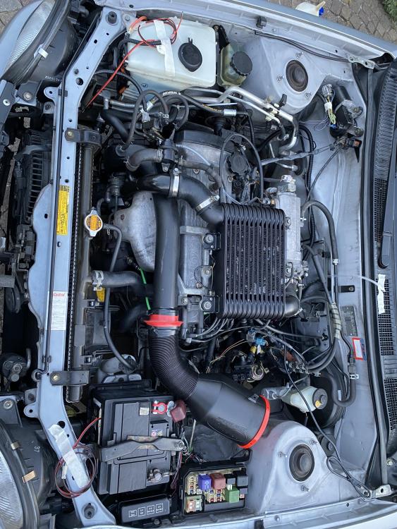
THE PIPES TO THE STEERING RACK VALVE, you can blank off most of the starlet lads do this, ive blanked them off on both my paseo and ep91 build. i cant tell any difference with engine loading at low rpm.
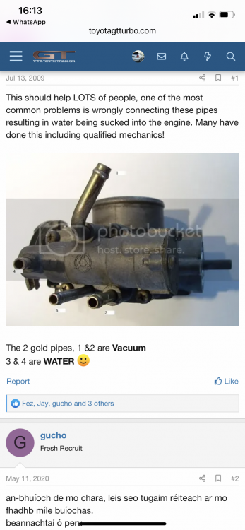
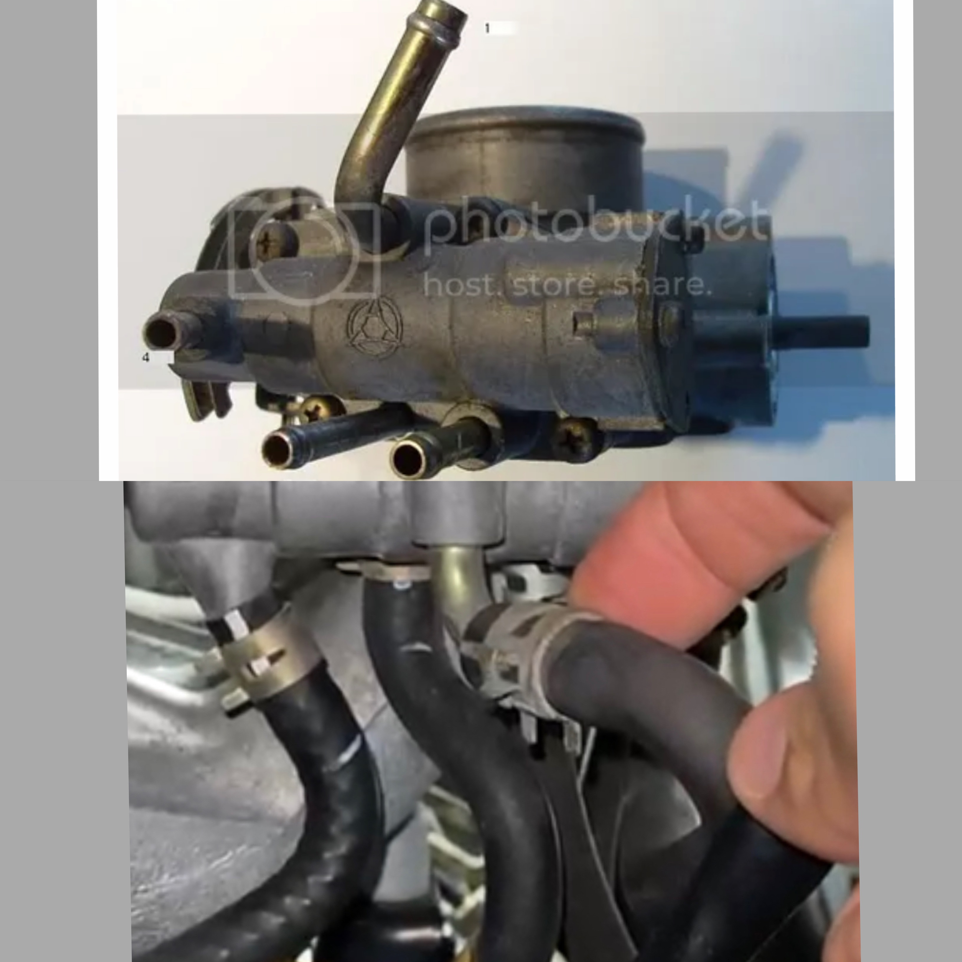
the blue electric valve in the picture is for the charcoal canister. this is a big round black canister that sits against the bulk head. the job of this canister is to store fuel vapor from the fuel tank breather (YOU CAN TRACE THE FUEL TANK VENT PIPE, IT GOES UNDER THE CHASSIS TO THE TANK) making it a enclosed system, environmentally friendly. when this opens the engine draws out the fuel vapor that is stored in the canister.
you can remove these (valve, pipes & canister) and blank off the pipes to the engines throttle body. ive done this and i use a motor bike fuel tank vent valve on the fuel tank breather pipe, this allows the fuel tank to draw in air as the fuel level in the tank drops.
this does also bring performance gains.
firstly it stops the older saturated canisters (these require replacing) from causing a vacuum in the fuel tank, when this happens the fuel that the fuel pump is trying to deliver to the engine is being sucked back to the tank. next time you fill up see if there is a sucking noise from the fuel cap as its removed. if so the canister is ready to be replaced.
also the throttle body area is a key area for the inlet system when there are more pipes added it causes air turbulence where these pipes meet, this reduces both peak flow rates and air velocity/speed.
it really neatens up the engine bay.
i will put a picture up of the vent valve.
1*Motorcycle Tank Gas Fuel Valve Breather Hose Tube Vent-Cap For Dirt Pit Bike | eBay
no engine warning light or diagnostic trouble codes are stored.
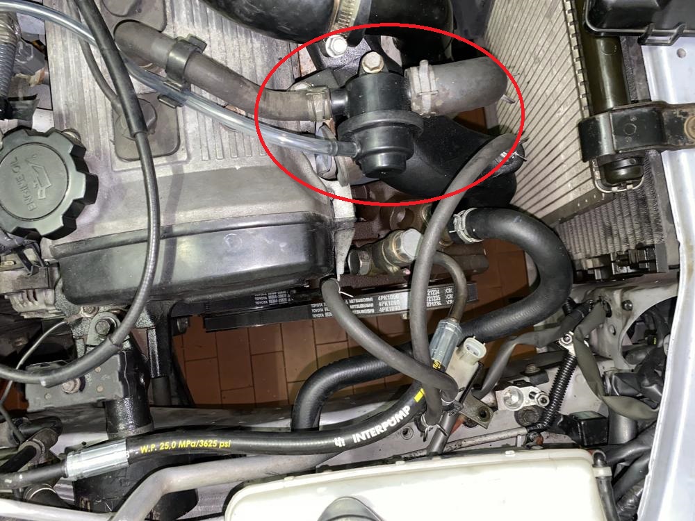
the black electrical valve circled in the picture im told is to help the engine when it comes under load from the air con pump, providing a slight increase in rpm at idle when the air con is on.
im really enjoying your build great work, keep it up. its going to be something special.
Thank you for this information.
I have the Corolla canister that is quite big. What’s your suggestion? Should I remove it and put something smaller? You are suggesting to take the blue valve off and blank off the small hose? I am not in front of the engine right now but if I remember well there are two big hoses that go in the blue Volvo and one small hose that go from it to the canister. Is that correct? your idea is to get rid of them all and put the motorbike tank valve? I would have to buy three of them for the three hoses? Can you send me a picture of the details whenever you have time? Thanks
I found two pictures. One shows the valve with the two hoses. They are not three. My apologies. One goes in the valve and one goes to the canister. How should I modify it? should I put the motorbike tank valve straight in the hose coming from the engine?
The other picture shows a connector that we cannot figure out. What is it? My friend was talking about bus control I thought that loose control was the valve with two hoses attached on the turbo air outlet. Can you confirm that?


-
On 7/28/2021 at 2:59 PM, Claymore said:
Looks good Frankie 👍
Thanks!
-
Thank you for the info guys!
i’m figuring out what this connector is. Can you help?
-
On 7/25/2021 at 4:26 PM, Claymore said:
I am already aware of the gains from removing the restrictive "EFI" pipe, airbox and piping to reduce the upstream pressure drop created by them (as are most people on the forum by now I think?)
Sock filters are best left to itb trumpets in my opinion and the amount of oil used by ITG on the panel filter I had on a previous car was ridiculous and it dripped out coating the bottom of the airbox (not good for a turbo to ingest).
It is important for a cone filter to have a trumpet base also to help gather more air than a straight pipe, good performance gains here. Element / filter area of significant size to reduce the pressure drop of filter and also to choose the correct media (stainless gauze, foam or cotton.) The bigger the better as far as I'm concerned, more surface = less restriction and balance the size of filter against the material to get the correct flow depending on room in the bay.
Also be careful the silicone pipes and couplers don't suck flat, it is often best to use aluminium pipe as much as possible with minimal silicone to prevent this. Not usually a problem until the Turbo is larger and sucking hard but worth considering.
Yes, the Turbo intake pipe (TIP as commonly referred to in other circles) is nicknamed the EFI pipe as some models had 16 valve EFI sticker on them.
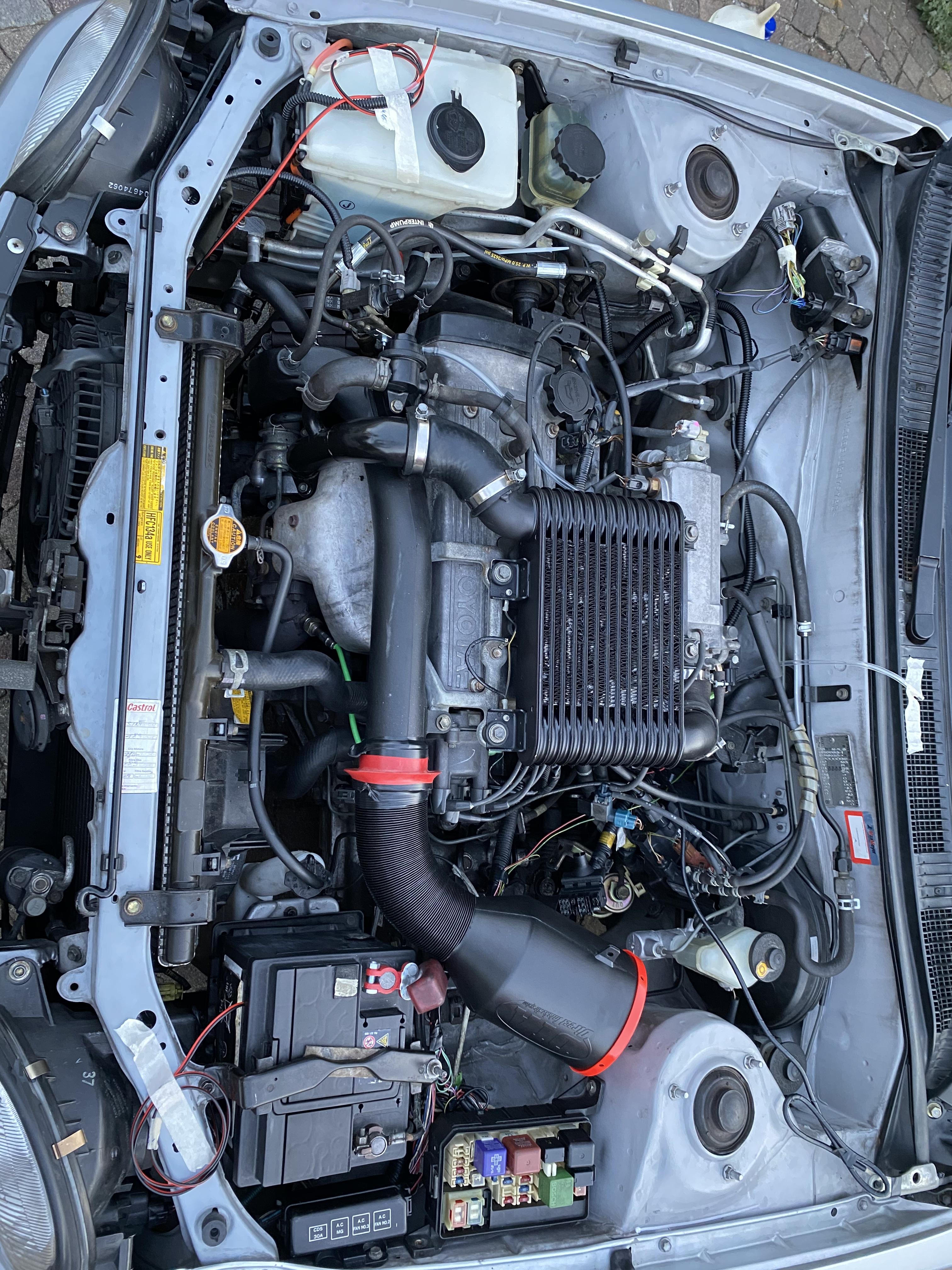
I also don't think the cover on the intercooler is the Turbo because it has a sticker that says turbo 😉.
Hope your family member is recovering well.
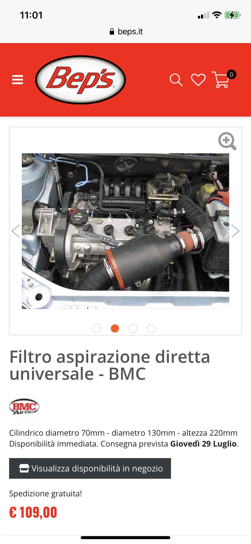
I bought this air filter for engines below 1600 cc.
-
58 minutes ago, RoyalDutchie said:

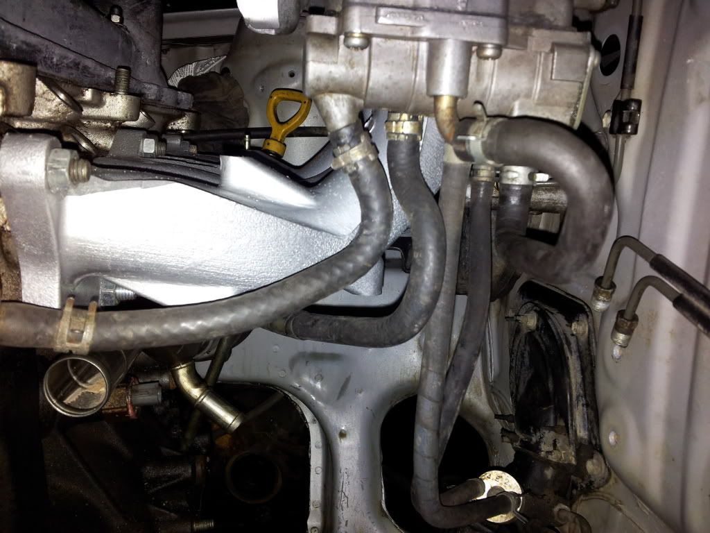
This looks pretty sketchy. Does the oil filter still seal well? I've been told the d1 spec sandwich plates fit without any work. Not sure if this is true, didn't try it myself.
It is catchy. They do not fit. They touch the steering pump bracket. We are modifying it right now because I refuse to modify the bracket. We will see if it still works and doesn’t leak.
-
17 minutes ago, Claymore said:
The Nuts are m 8 x 1.25mm. Get some strong, thick washers as well because the Tuning developments downpipe holes are very big and the nuts can pull in!
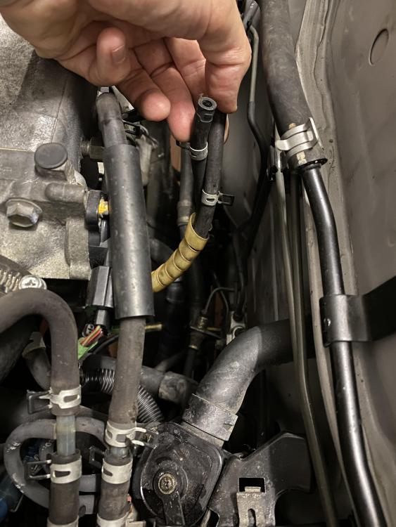
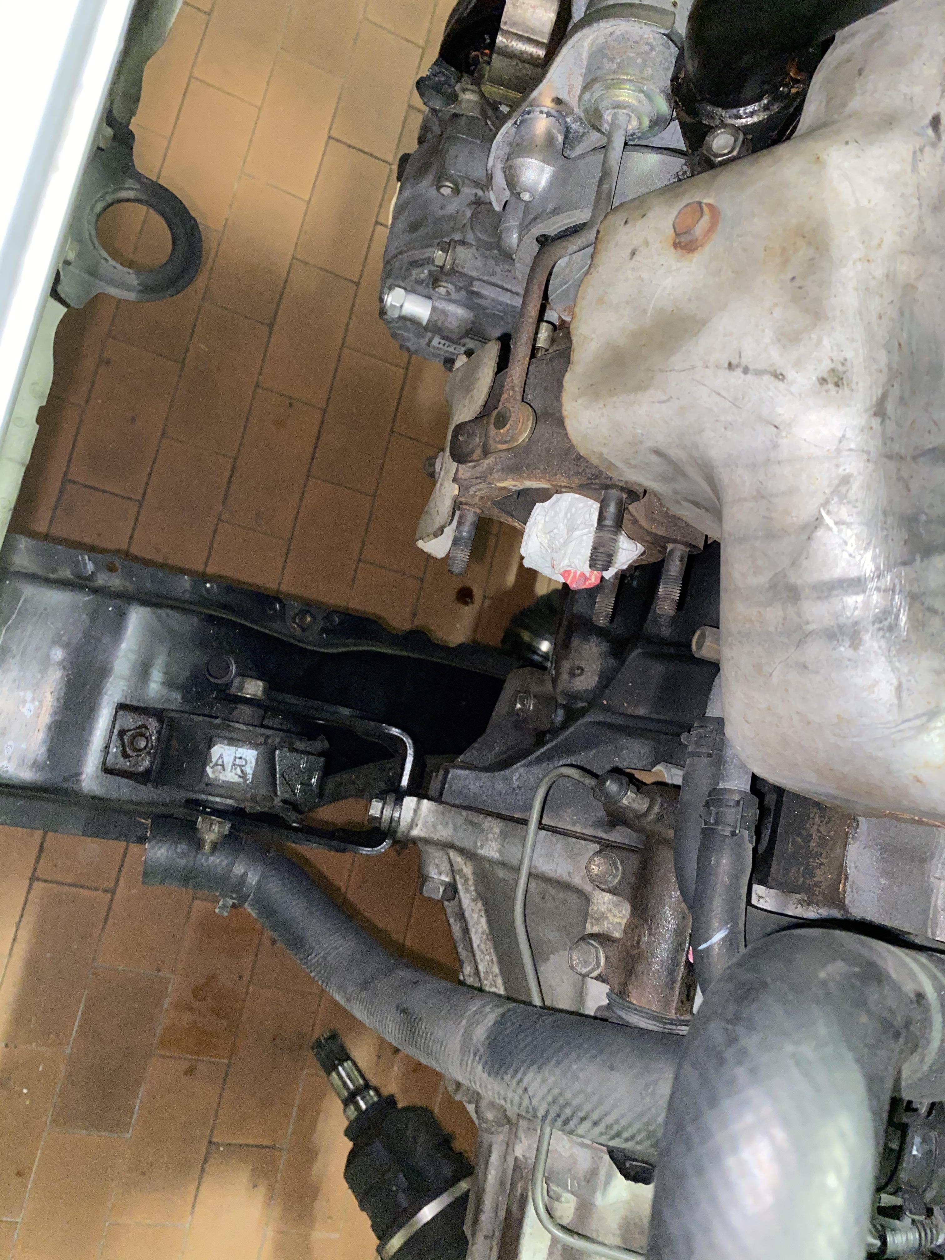
Thank you. I temporary put some nuts to bring the car to the shop. The guy will use some washers when he finishes the modification. The downpipe has to be cut and has to go around the lower chassis. I bought the lambda for the downpipe with one wire. My boy is getting the wire to its original connection.
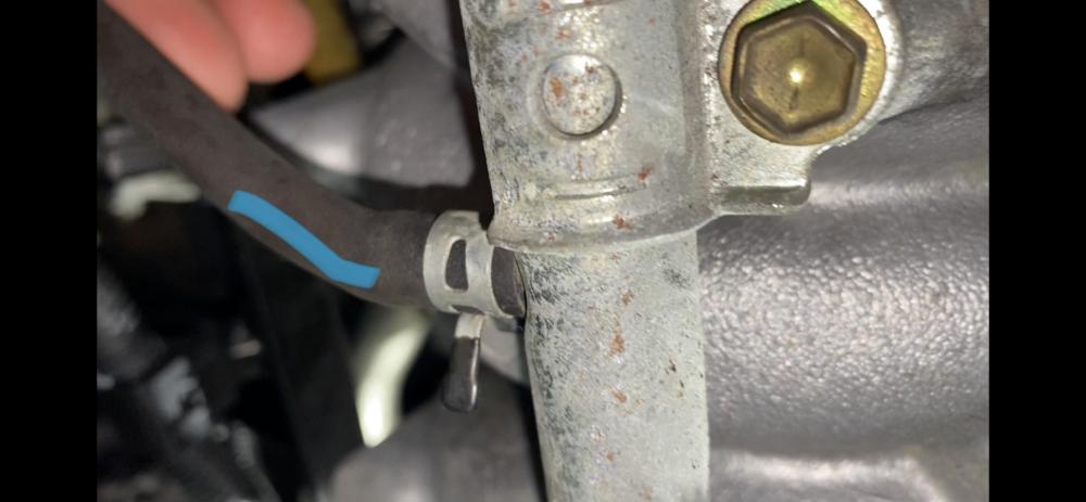
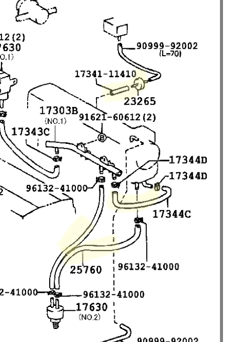
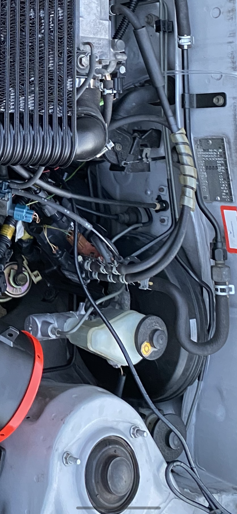
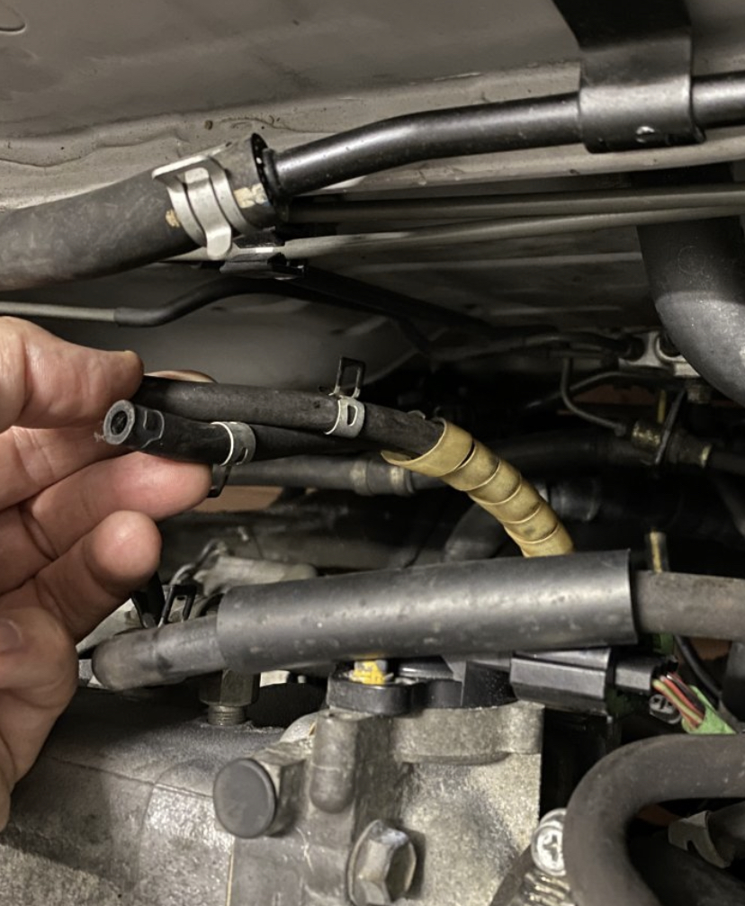
Now I really need now where the 2 air hoses (vacuum for low rpm) can be connected. One pipe comes out of the lower throttle. The other from the lower part of the inlet. The are short and hanging there. Can you help?
these two air hoses go where they should. Should I modify some thing here to connect the two RPM air pipes? does this make sense? If so, how and which hose where? thanks
-
I forgot to ask. Which nuts size and step should I buy for the turbo CT9 exit for the downpipe?
90179-08082
-
On 7/25/2021 at 6:46 PM, Claymore said:
I'm simply trying to help Frankie make an informed decision by adding info I feel is relevant. The more info on the forum to help people the better.
And it is very much appreciated. Are you guys are helpful and I believe that all my questions and digging is precious for everybody on this platform. I spent thousands of euros and months of research to make this beautiful dream happened also gained by your pride and love for these engines. I am glad we are here exchanging great energy.
today I will see my boy to continue the work. I received the down pipe from tune developments. Hi will work on a few things and then try to figure out where those two vacuum pipes (that originally go to the vacuum pump on the Starlet) Will get hooked on my Corolla. My car has that acid pump input on the steering pump. I need to do the same elsewhere. I hope you can help with a simple example.
first issue is to adopt the free hose pipes that originally go to the vacuum pump that I do not have because the Corolla uses the steering pump to vacuum. I need a solution.
I bought oil Sandwich gauge but it doesn’t fit because it touches the steering pump bracket. We will have to try to peel some metal off it to get it in line. i’m not even thinking about taking the bracket off and ruining it for a gouge adapter.
let me know if you can help with the pipes please.


-
On 7/25/2021 at 3:21 PM, Sam44 said:
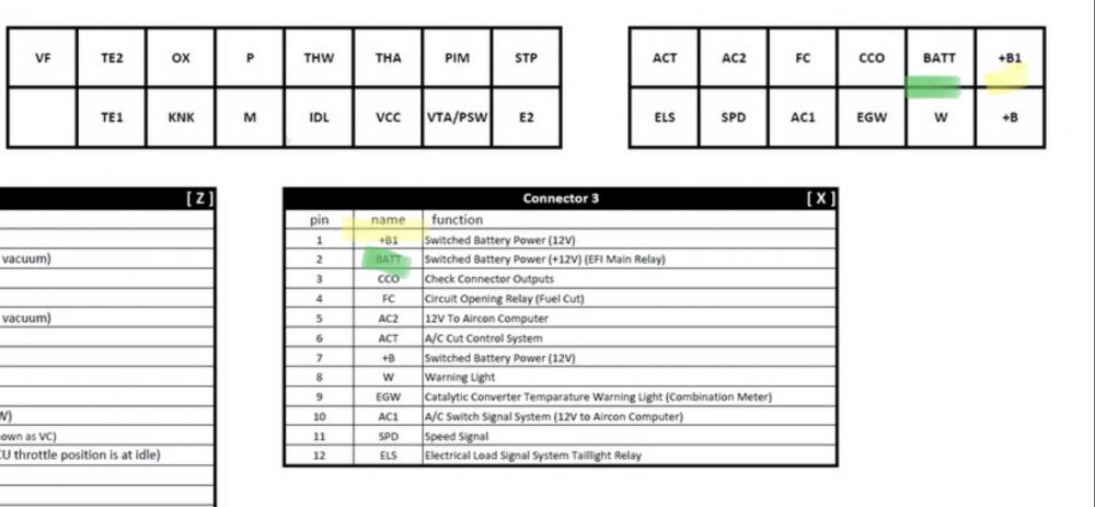
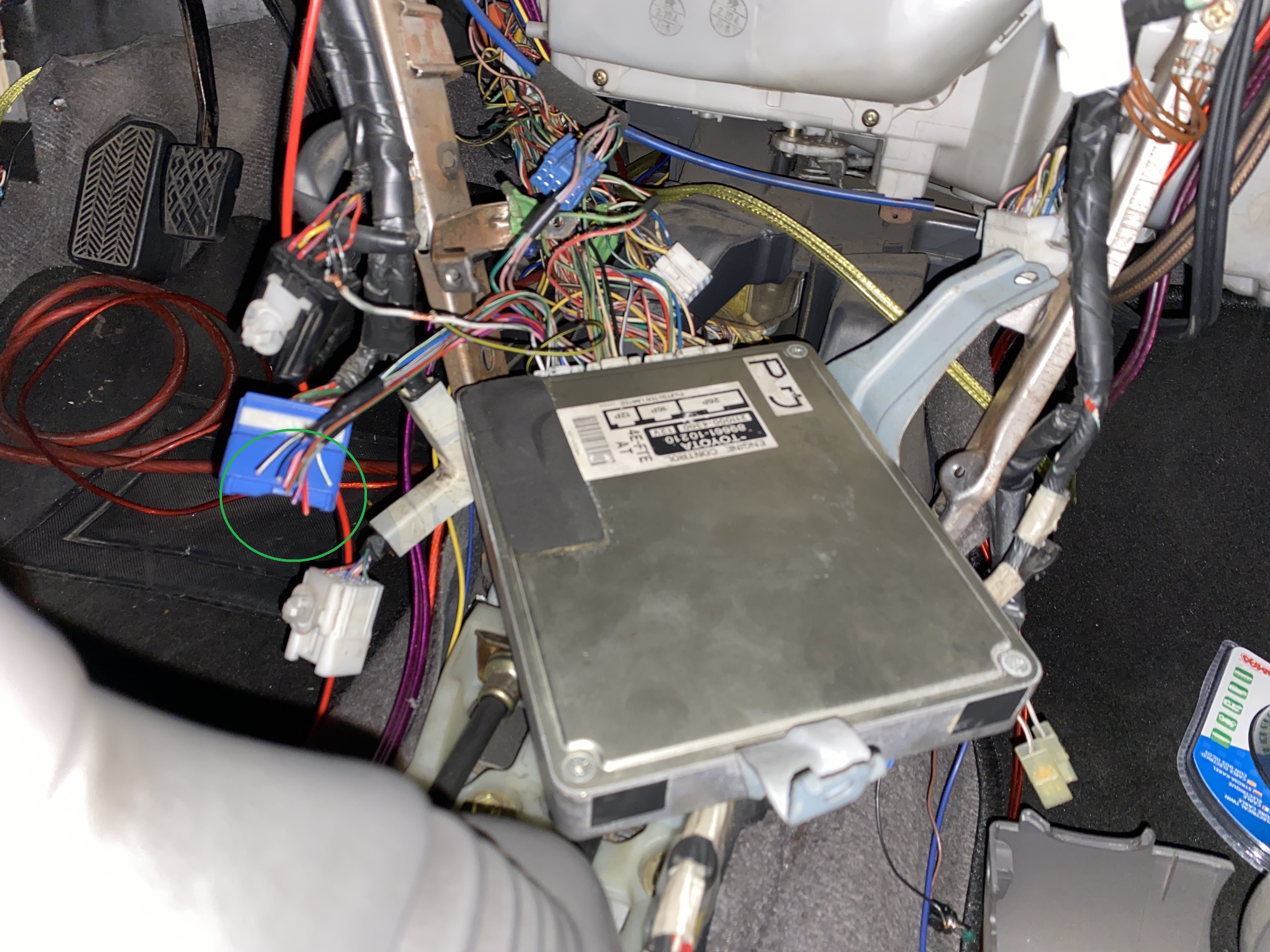
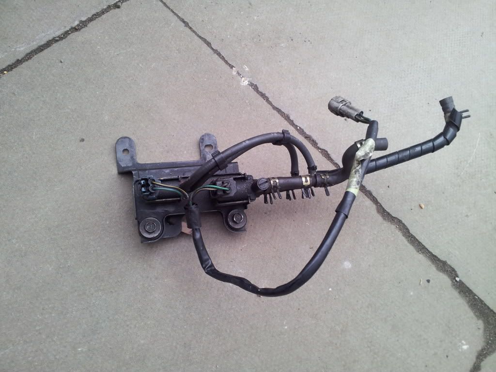
the wires in the picture are for the auto ecu/vehicle abs. not needed, also not found on the manual 4efte ems/ecu.
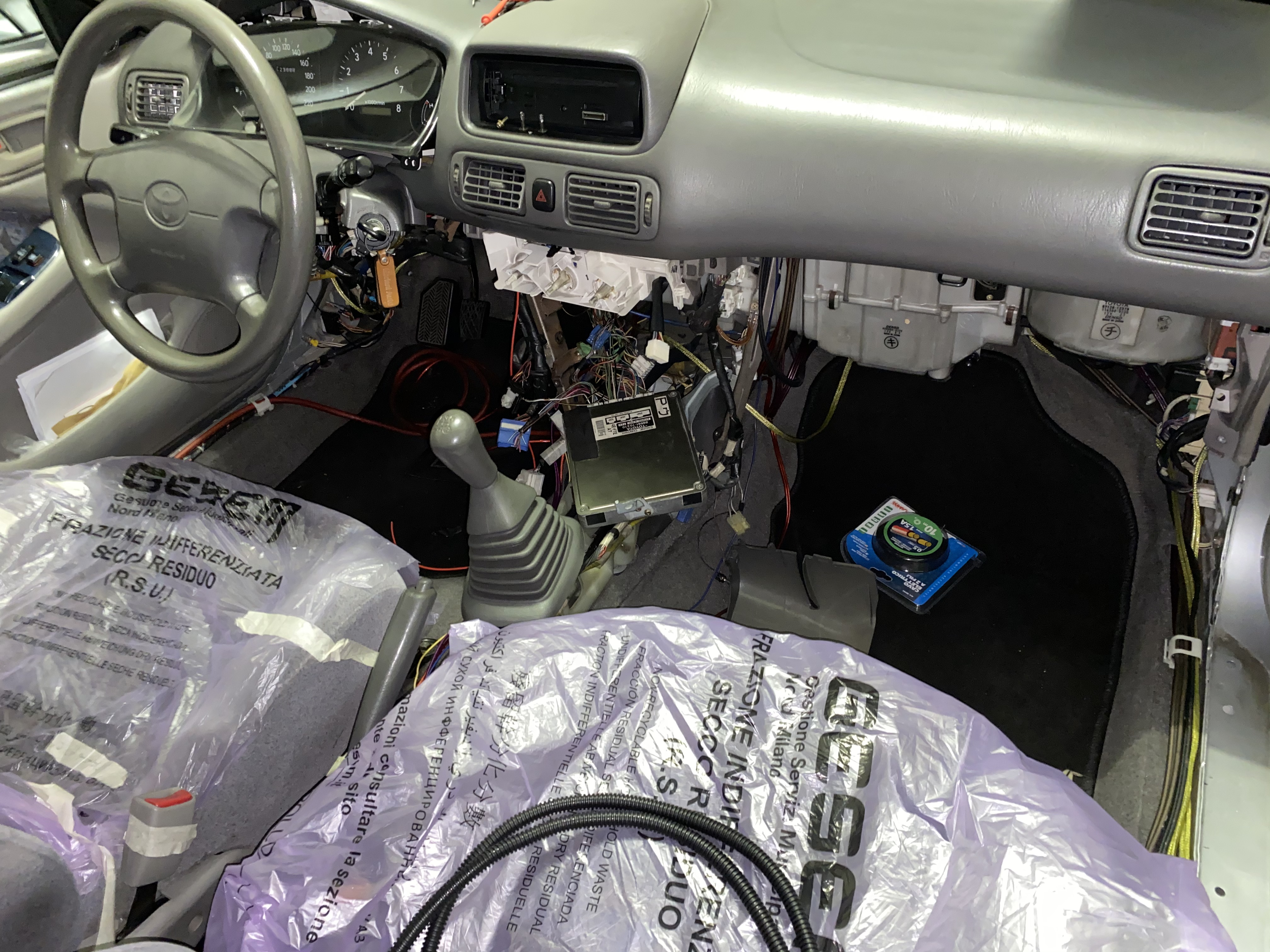
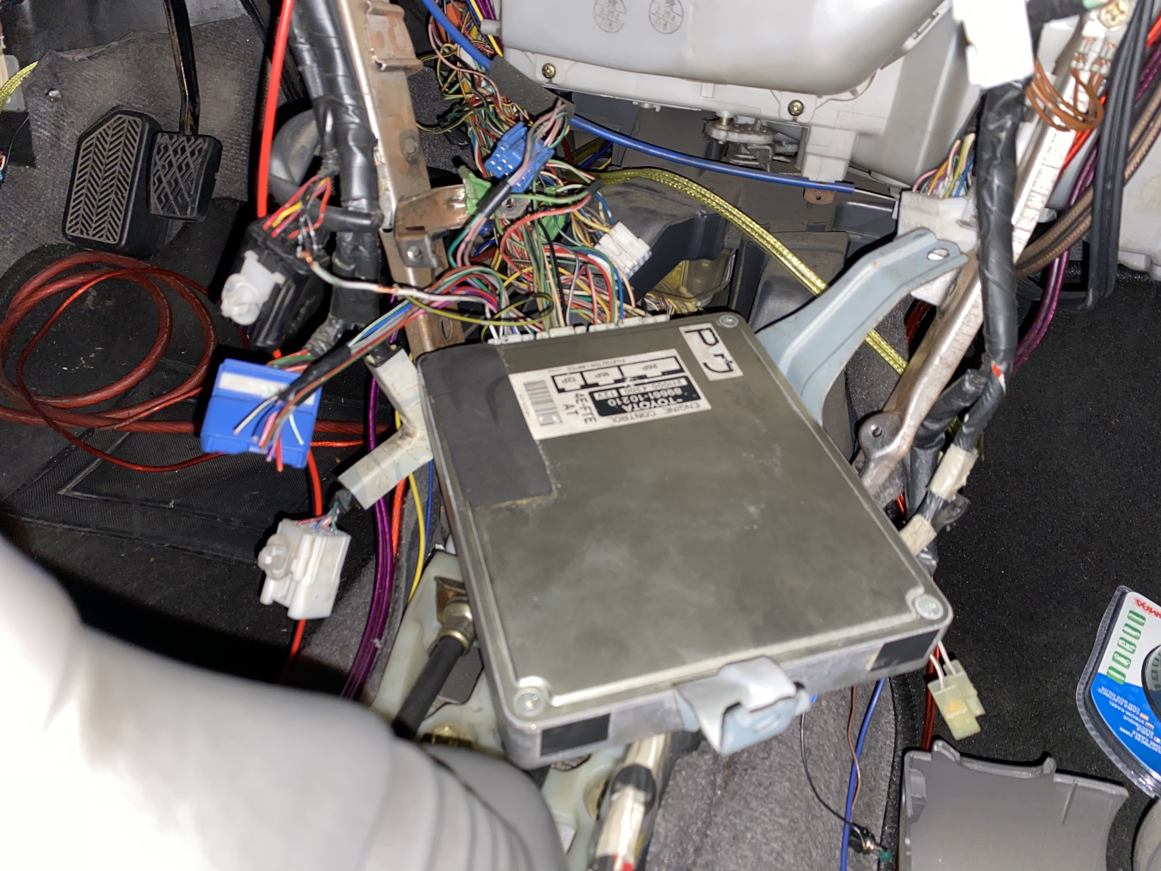
Thank you Sam! We are going step by step, function by function. If you have an updated diagram with the ECU outputs for the auto to manual ECU fix it will be very useful. We are using the amnuals and ECU pinout info.
-
On 7/25/2021 at 2:20 PM, Claymore said:
Looks fine in this picture? Did it break later on?
Nice work on the power steering High pressure hose, looks very professional.

Thanks. I spent €120 to exchange connectors on the stearing pump and AC hoses to keep my Corolla pipes but use the fte steering pump and AC. THE GUY IS A PRO AND BUILDS PIPES FOR Ferrari.
-
On 7/25/2021 at 2:16 PM, Claymore said:
That's not a "hot pipe" it's the "EFI" pipe and it's the intake tube for the turbo. A "hot pipe" is the pipe carrying hot compressed air from the compressor housing of the turbo to the intercooler. "Cold Pipe" is the pipe carrying cooled air from the intercooler to the throttle body.
You can leave the EFI pipe in place and blank off the mounting hole whilst fitting a breather to the rocker cover and an atmospheric dump valve to the hot pipe.
http://jamesdrake13.blogspot.com/2012/03/how-to-install-monza-ssqv-blow-off.html
This way no boost creep by removing the EFi pipe, fixed problem.
Or:
I would get the car running with as close to standard setup for now and then look at modifying and improving slowly over time. It becomes a spiralling project where you end up changing everything as you go along and it takes a long time and costs alot of money. Its up to you as its your car. The cheapest way would be to just fit a standard dump valve to replace the broken one.
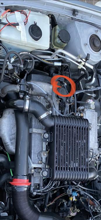
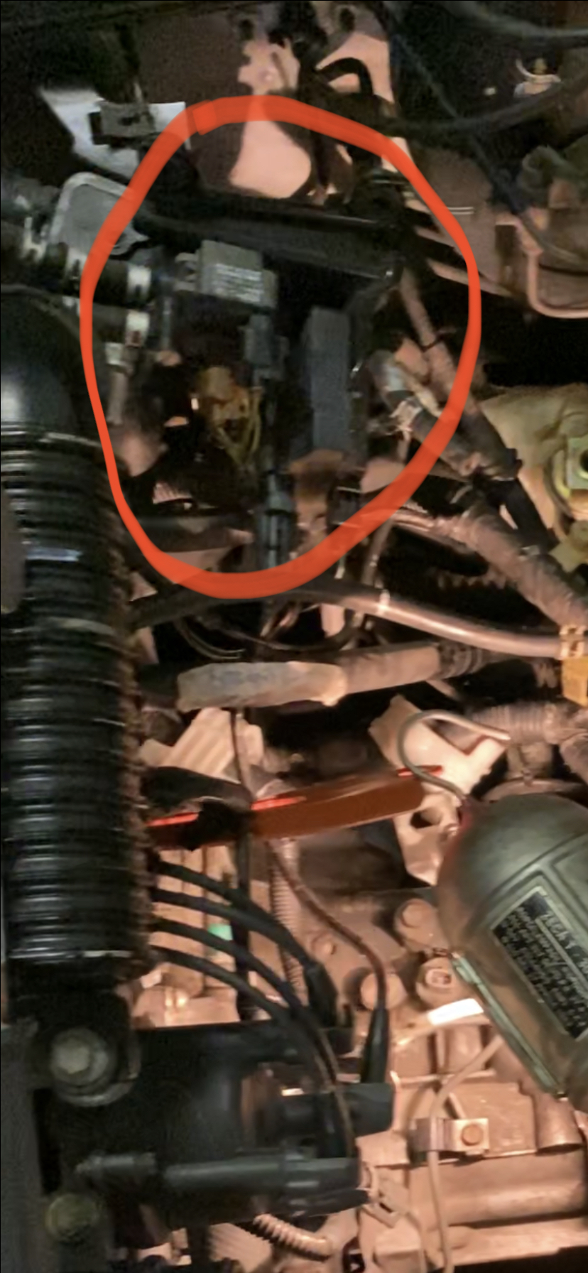
Wiring, I hate to state the obvious but are these wires important (green circle)?
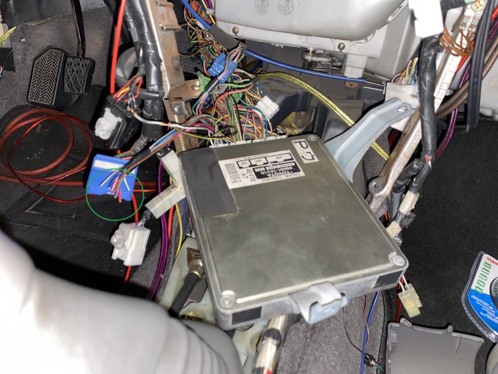
Also when using an Automatic ECU and wiring loom I think you have to bridge some wires relating to the gear selector position wiring? Something about sending a signal to the ECU to tell it the gearbox is in Park or neutral or it won't let the car start? I think you have already found this information in an earlier post but did you do it?
Hi. Yes I bridged the gearbox connector. I saw it in a video. A British kid dis the auto to mNual conversion on a Starlet.
-
On 7/25/2021 at 2:16 PM, Claymore said:
Wiring, I hate to state the obvious but are these wires important (green circle)?
These wires are all functions listed here. What do you suggest?
-
On 7/25/2021 at 4:35 AM, Sam44 said:
I'm looking into this now. It's best to remove the hot pipe and use a aftermarket silicone hose from the turbo (air filter relocation kit) going to an aftermarket air filter, placed were ever you decided in the engine bay. This pipe in the picture (hot pipe) is very restrictive to power output. The only issue here is if you remove this and also use a aftermarket exhaust system (higher flow) you will get boost creep and hit fuel cut (not good for the engine at all). You have to enlarge the turbos waste gate hole (increase its diameter) so as to not get boost creep. as well as use a aftermarket bov (blow off valve) in place of the recirculation valve circled in the above picture. The proformance gains doing this are great.
I'll be on the wiring tomorrow.
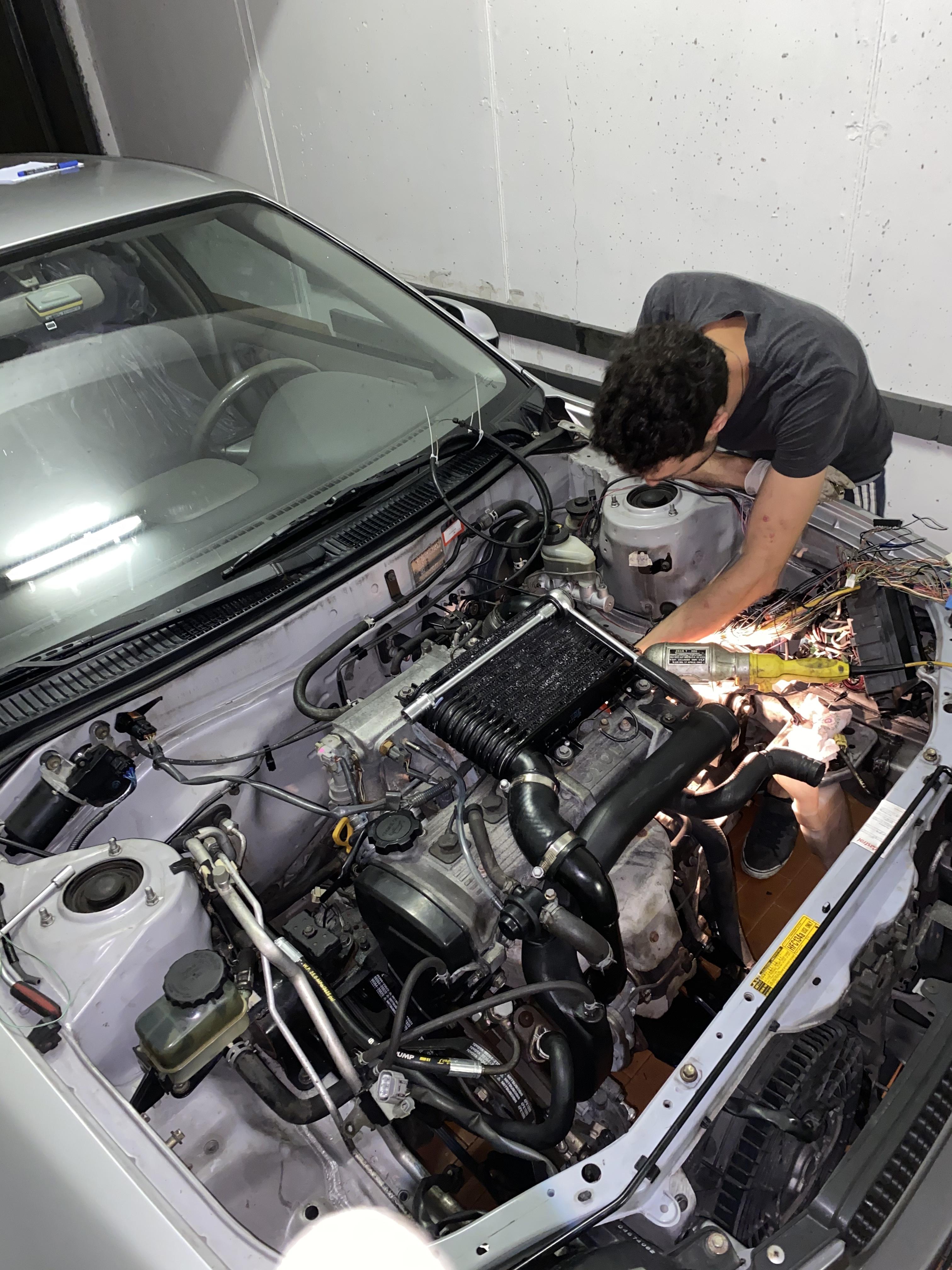
This is interesting. Will discuss it with mp partner tomorrow. In the meantime we fixed the cracked peace. It holds so far. But I do wanna plan upgrade using all this info as soon as the engine will rune with all its sensors and wiring. We are at 70%.
We didcrank
alternator
fuel pump
vent sensor
water temp sensor
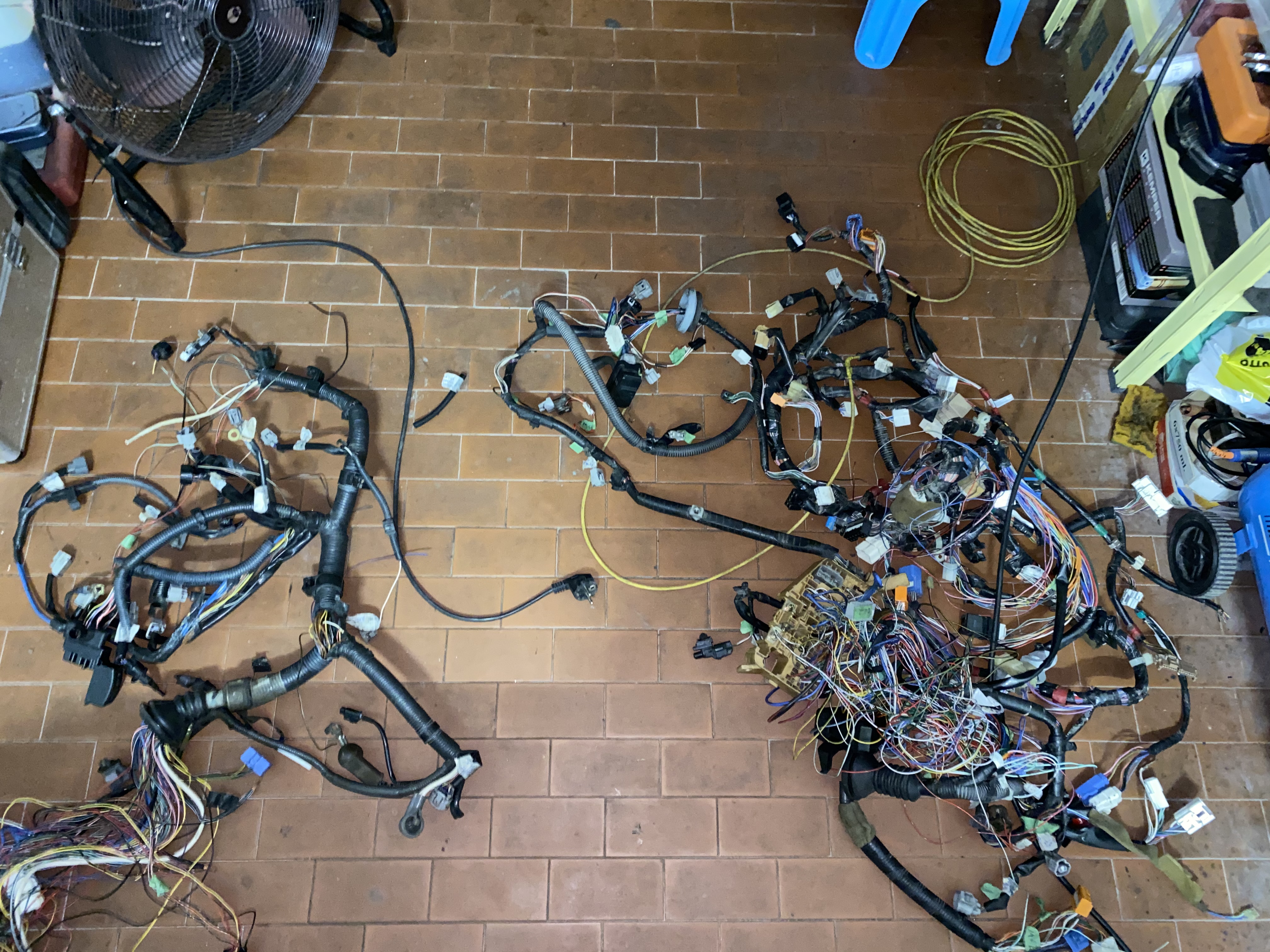
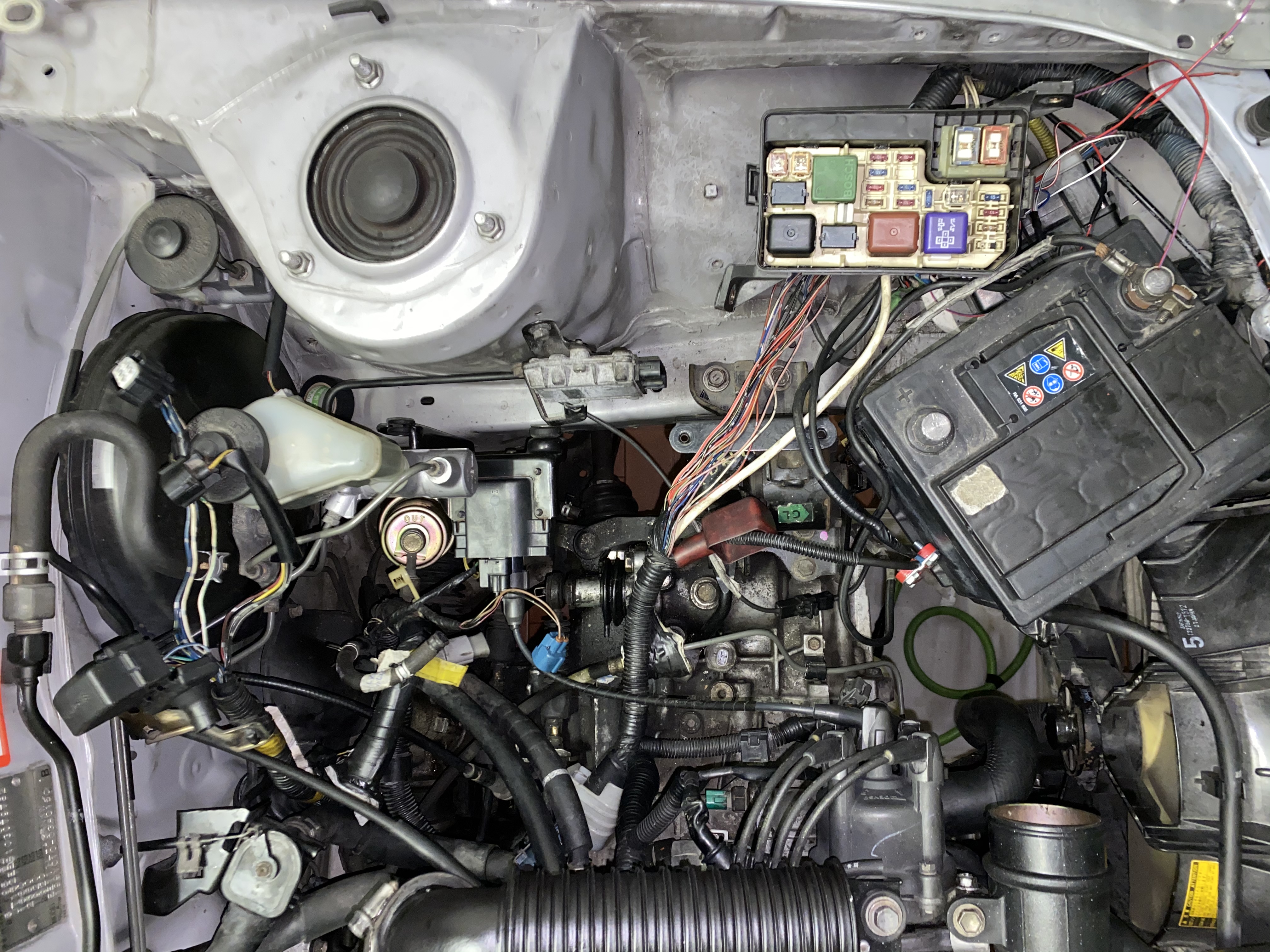
Consider that all the extra loom parts has been cut from the Starlet fusbox loom to be integrated in the Corolla fusebox loom. Not an easy task.
-
On 7/25/2021 at 4:23 AM, Sam44 said:
Look at the top of your steering pump you should see the same valve as on the picture above they can also be routed to there (same valve going the same job).
Amamzing. I will check!
-
On 7/25/2021 at 4:23 AM, Sam44 said:
I've been busy building the back garden to how the misses wants it as well as all the house hold jobs that need doing. (Lots of them)
I feel you! Hope all is well
")
-
On 7/21/2021 at 2:25 AM, Frankieflowers said:
I agree with you even though I bought the two adapters because someone told me there is a sump sensor for oil temp which is not true. I wasted €50. Now I bought the plate he suggested. Thanks
Funny story the sandwich doesn’t fit. I went to research and I found out none of them fit if you don’t forge some space in the steering bracket. Not gonna docthat. I’ll try to adapt the filter adapter instead.
-
On 7/25/2021 at 4:50 PM, Sam44 said:
attention of frankie: i have seen efi pipe to re circulation valve blanking plates to remove the standard plastic valve and install a aftermarket bov (blow off valve).
Thank you Sam. I need some pics of how the air hoses are connected to the blow pff valve.
my issue now is that the 2 free air hoses that normally go tocthe vaccumm pump on a Starlet, on a Corolla go to the steering pump. So how am I gonna fix this? Thank you all

Corolla

-
On 5/16/2013 at 11:43 PM, daniel_g said:
If you have this still attached to the coilpack ignitor then get it in the fucking bin and block off the top TB ports. Just causes hassle and random vac lines everywhere.
http://i1149.photobucket.com/albums/o585/daniel_gg/20130324_153420_zps3bd4293c.jpg
And the carbon canister that lew mentioned.
This is the best pic i have atm of the vac pipes youre talking about.
http://i1149.photobucket.com/albums/o585/daniel_gg/20130318_201038_zps72e5be8e.jpg
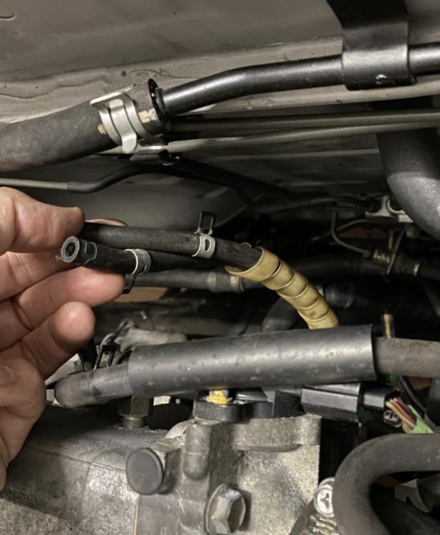
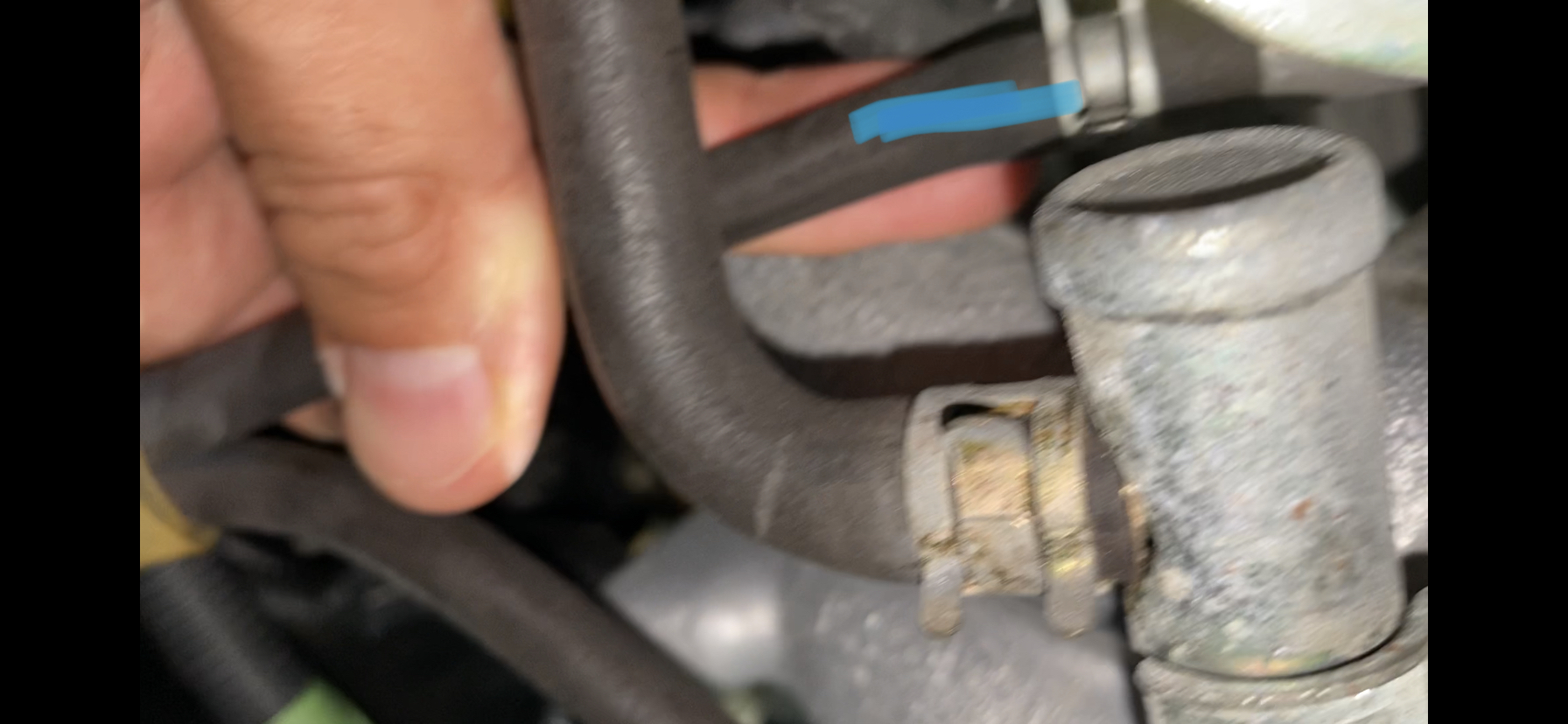
Anyone still here? I’m having trouble with a few hoses. Swapped the engine in a Corolla. I don’t want to leave anything hanging. The two pipes I have a loose are apparently one for water and one for air. One of those plastic spirals is holding them together.
@Jay send me a picture of the throttle. Number two is next to another hose which isn’t on the throttle but on the inlet right next to it I need to know how to connect them and where. Thanks


-
Updating my swap. Although I will post everything when the job will be done, the hard process is still in progress. The wiring. I managed all the mechanical parts. Now I am struggling to adapt the FTE loom to the Corolla 4efe. The engine bay relays seem to be running the same signals as the FTE issues box. The ECU isn’t giving any signal even though it’s connected to the engine and should have it’s 12V power. I need help.
-
13 hours ago, candy_red said:
I stand by the sandwich plate option being the best just because you can mount both pressure and temp sensors.
Although another solution would be to place it in the sump but that requires removal drilling taping and then resealing.
I agree with you even though I bought the two adapters because someone told me there is a sump sensor for oil temp which is not true. I wasted €50. Now I bought the plate he suggested. Thanks


4efe SWAP to 4efte in Corolla E11 1998
in 4E-FTE Engine Discussions
Posted
This is true. I actually remember that every time I open the tank it does that sucking noise! I want to replace it but maybe put a smaller one? Or maybe do as you said with a motorbike tank valve? Where exactly should I connect it?