

Frankieflowers
-
Content Count
417 -
Joined
-
Last visited
Content Type
Profiles
Forums
Wiki
Media Demo
Store
Calendar
Posts posted by Frankieflowers
-
-
On 2/22/2022 at 1:57 PM, candy_red said:
ts really that easy though no need to worry about it. Its just a little time consuming.
Thank you for sharing. We had to switch a few shims that were out of parameters. Engine seems to be running OK now.
The problem now is that the timing procedure is reacting upside down. Setting +10 on diagnostic mode isn’t going to zero when unplugging diagnostics. I really don’t know why the electronics are acting like that but it definitely isn’t a mechanical issue because we did everything right. We already pulled down the camshaft 3 Times ever since I had to send out the cylinder head for welding. The distributor is very simple to fit and we haven’t touched anything that could compromise it’ from functioning properly. Setting timing to +10 on diagnostics brings it up to +15 when unplugging diagnostics. what is happening?
-
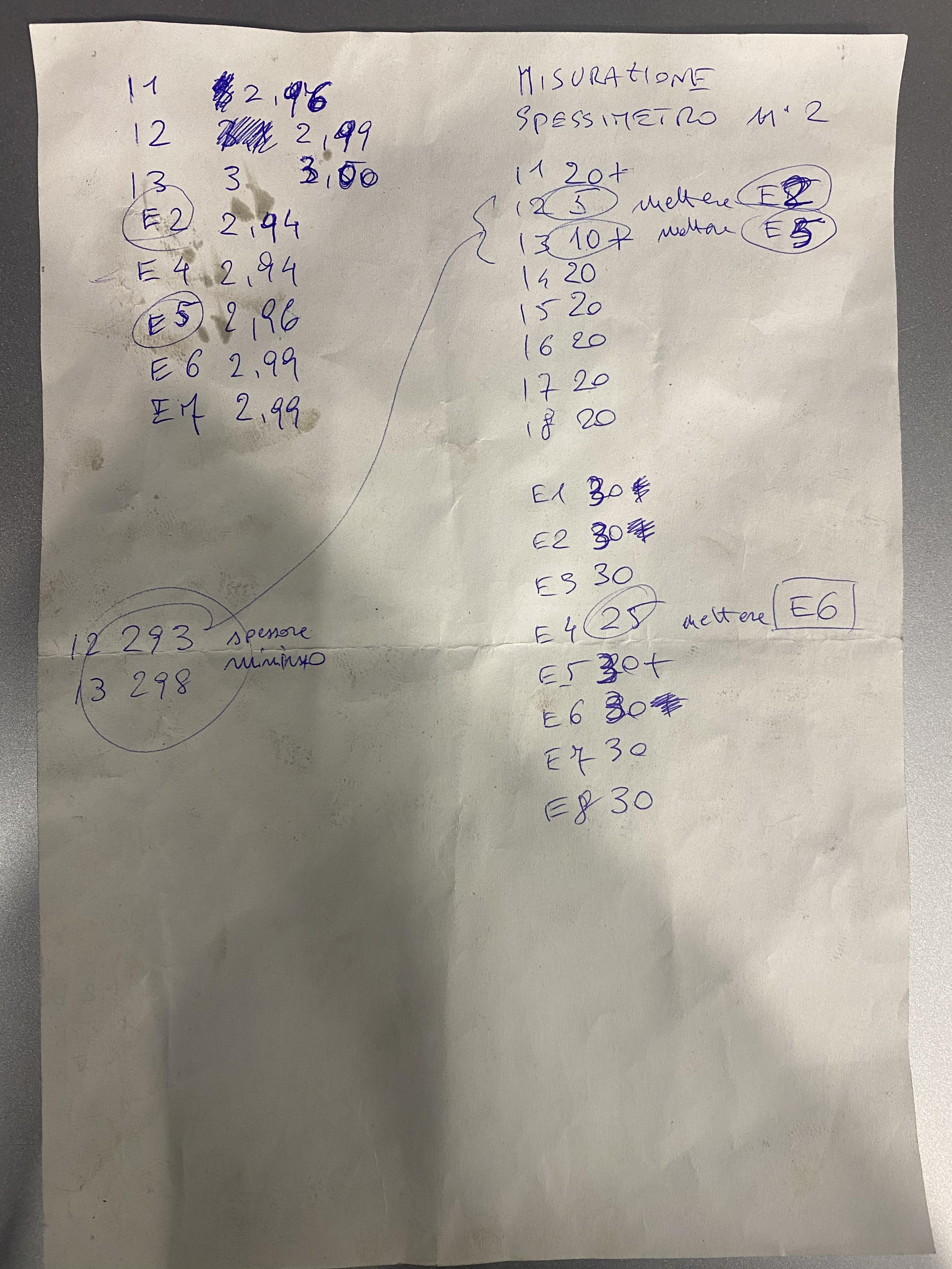
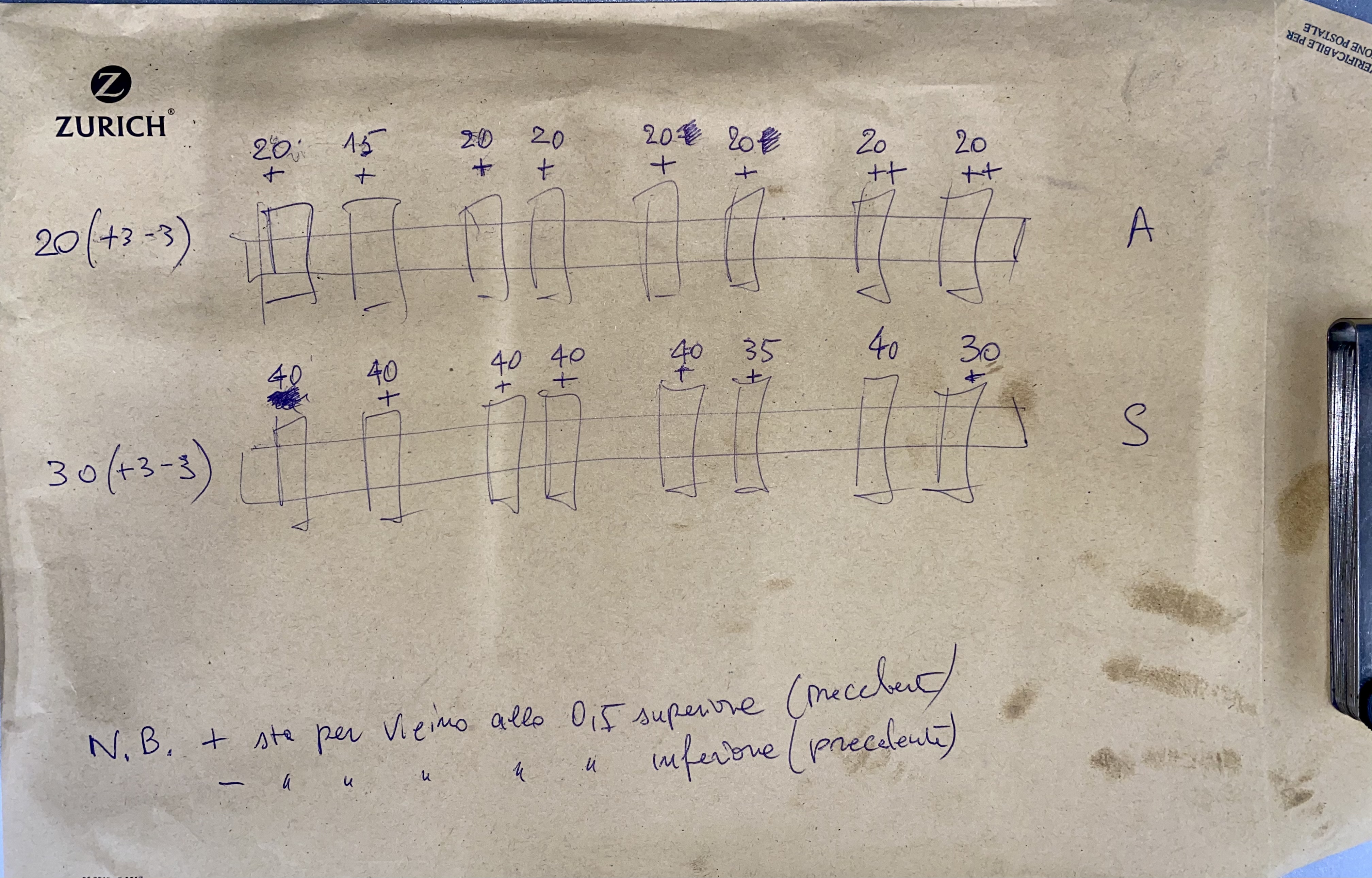
shims had to be moved around a few times...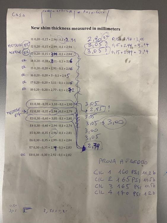
-
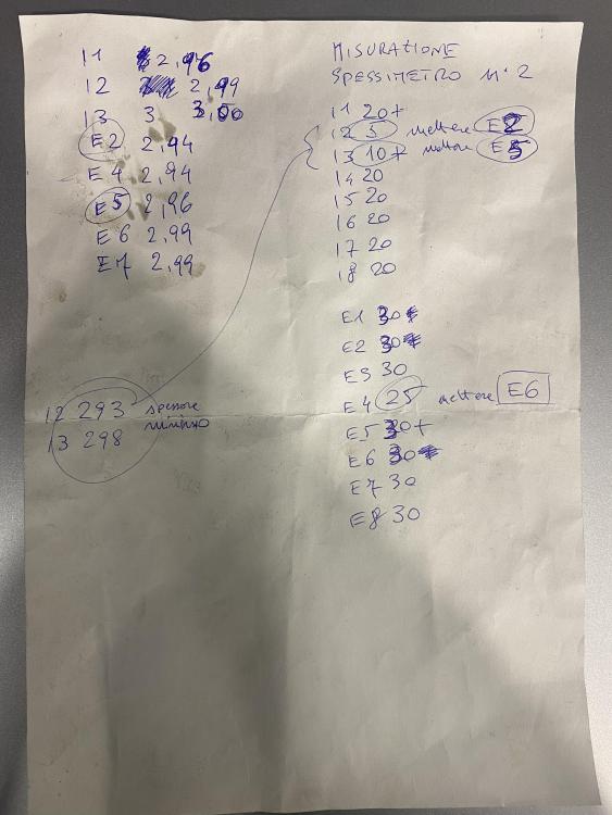
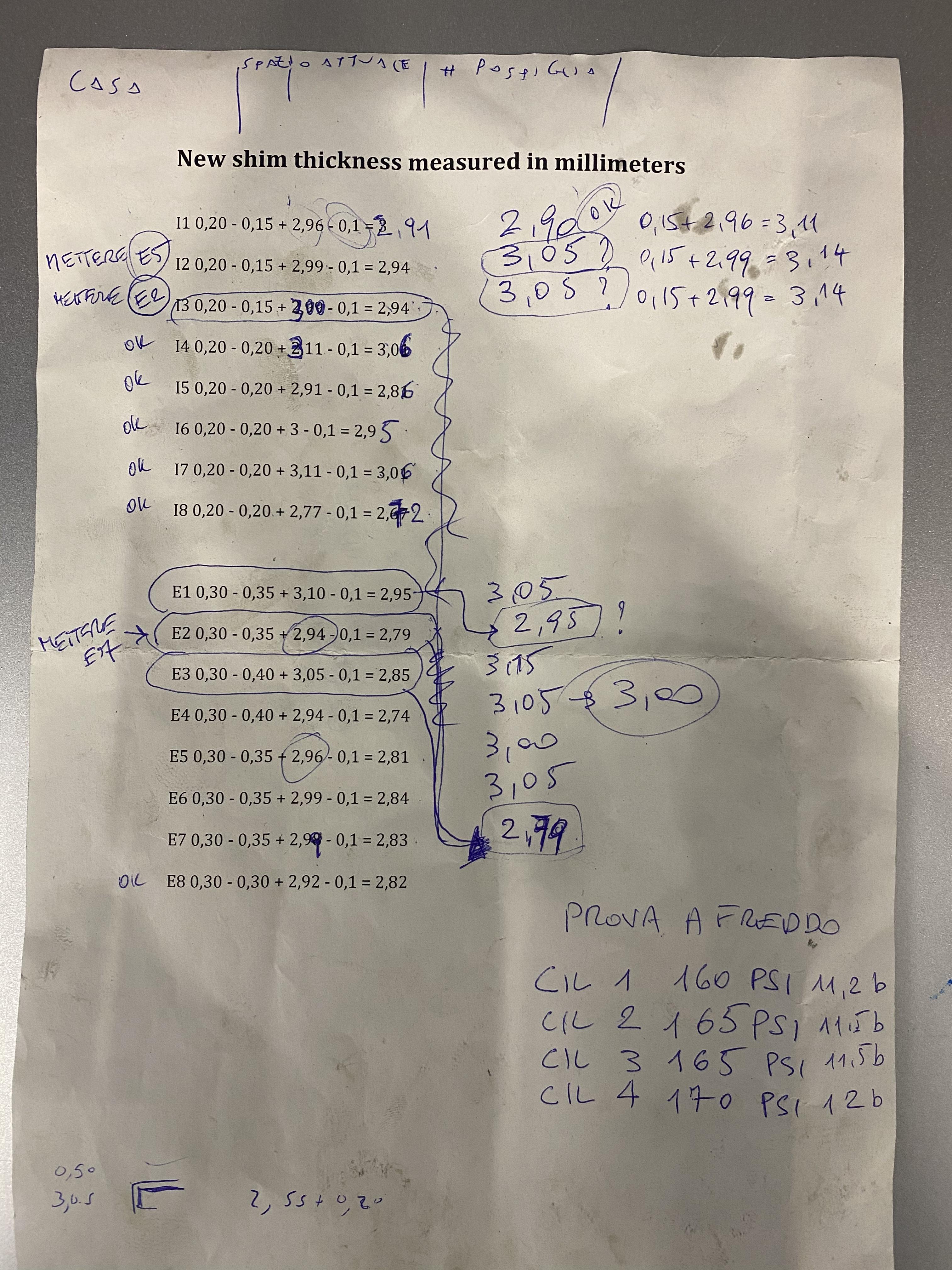
Update.
here are the valve clearance measures we took with the engine that was almost called. Let’s say 25°C.

before we did this I went to see the workshop that will change my echo and map the engine whenever it will be working fine and he ran a compression test when the engine was fairly warm The result was 140, 140, 150, 150 when I bought the engine from England, the seller sent me a video of the compression test that was 175, 170, 160, 165. As the engine temperature matters when it comes to compression test, I cannot be 100% sure of what has been done by the seller and I can only be certain of what I am doing this is sad, checking the valve clearance we have the certainty that the shims are thin enough to let the valves seal. If decompression is down is probably because the rectification work shop did the job wrong and the valves don’t seal properly anymore this is a consideration that my brother gave me and I agree. He also said that maybe the valves will adapt and the compression rate will raise again but who can be sure about that at first I thought that checking the valve clearance would give me a larger value beyond the limit that would mean that the valves don’t seal properly and a shim rectification would have been done it seems that my hopes or a let down.
The question to all. If the formula underneath is correct then how come the engine should have a compression rate psi between 160 and 170? Technically the result is wrong because with an 8.2 compression rate for the 4EFTE engine we are talking about 120 psi can someone explain this? Thank you
8.2 x 14.696 / 1 = 120 PSI
9.6 x 14.696 / 1 0 = 140 PSI
-
33 minutes ago, Sam44 said:
I've just had a read threw this.
I was thinking they had not seated the valve properly or a collet had come loose.the top of valve spring retainer I call the register.
Hope you get it sorted.
We did the cylinder compression test and it went down to 140 psi on the first two cylinders and 150 psi to the other two cylinders. It is obvious that there is a leak and apparently it is not the valve clearance instead it is the rectification done wrong.
-
I spoke to the Toyota chief mechanic and he told me that they usually measure the valve clearance and then the use the table with all the specifics to calculate the right shim thickness. They send the measures to a workshop to customize them. Another mechanic told me that usually they have a kit the use with different measures to see which one fits better but as we can see everybody has his own method.
-
38 minutes ago, Claymore said:
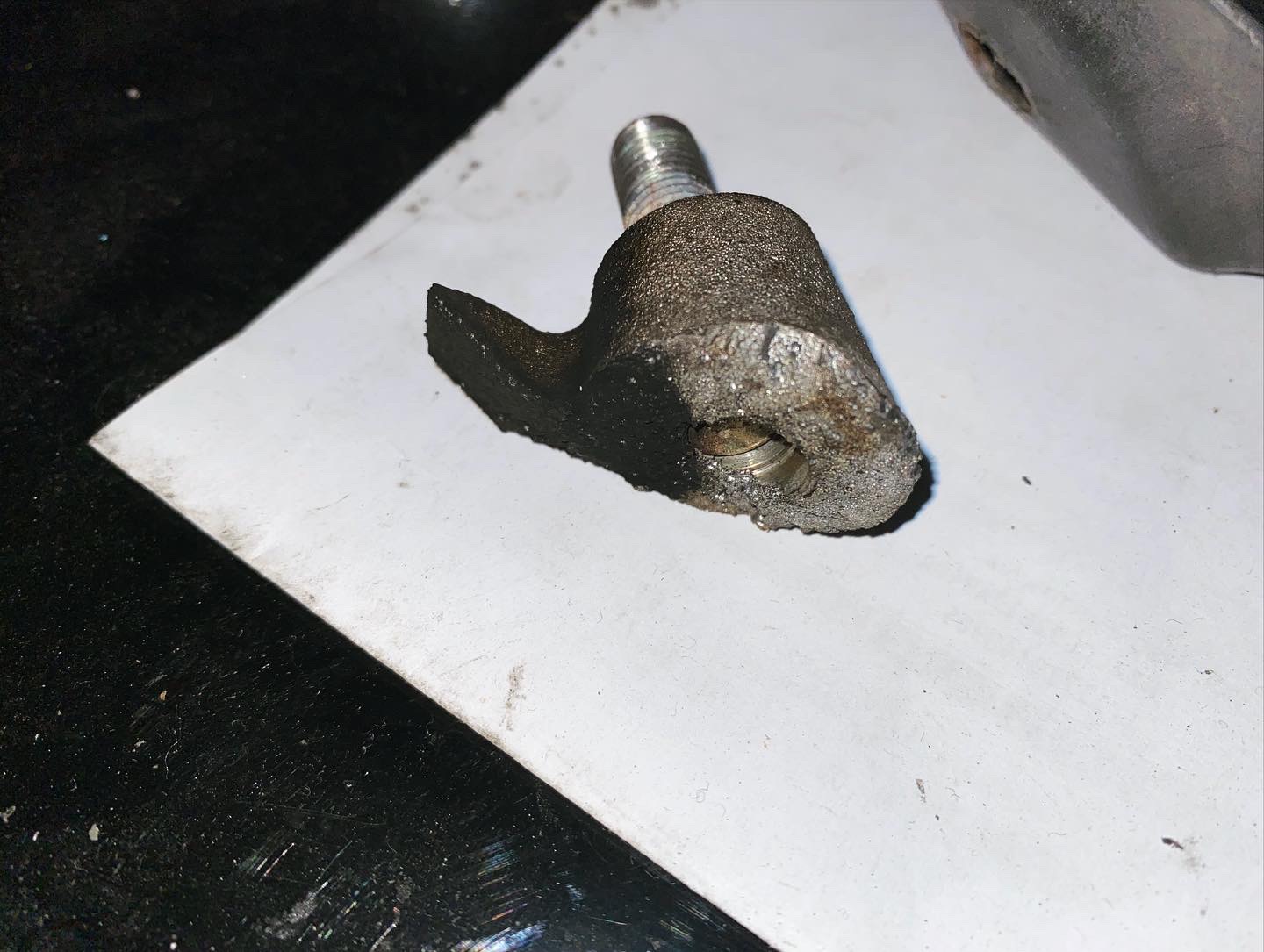
Toyota have special tools something like this:
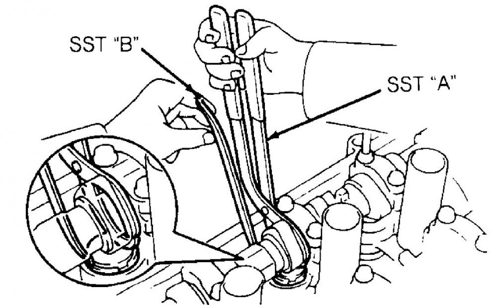
They push down on the bucket pushing the valve down and then you can change the shim.
I have seen it done with the cams in place but its not easy without the special tools and you could damage parts.
Get the clearances measured first. Then we will think about fixing things!
OK I will do that and write down the measures. I will update you in the weekend. Thank you very much
-
8 minutes ago, Claymore said:
Hey Frankie, don't blame yourself.

Depending on what machining work was done to the head and if the workshop put the same valves, buckets and shims back in the same positions will determine if and how bad the clearances are now.
Whatever happened in the past, I would now check the clearances to be safe.
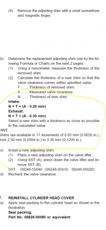
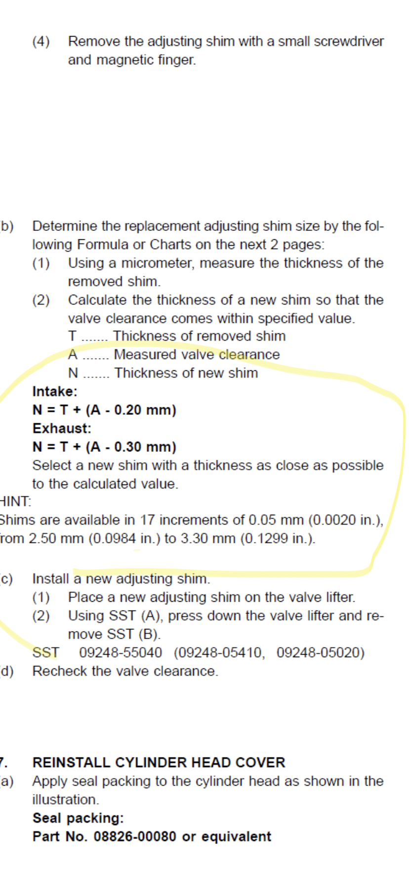
Measuring the clearance is easy all you need are feeler gauges, pen and paper. Once you know the clearances you have, you can then check them against Toyota specification. If any clearances are out of specification you then need to swap / replace shims to make the clearances correct.
@JamesG has the 4efte workshop manual in english, PM him your email and I'm sure he will send you it. It shows how to check the clearances.
Thank you very much. I sent a message to @JamesG I hope he’s going to be able to email me the workshop manual so at least I don’t have to translate from Japanese 😂
question. What if I need extra shims to do the job? Is it possible to pick them out without removing the camshaft? I saw a video of a guy in Thailand doing it with a few accessories. What do you think?
-
@Ryan-11 hello
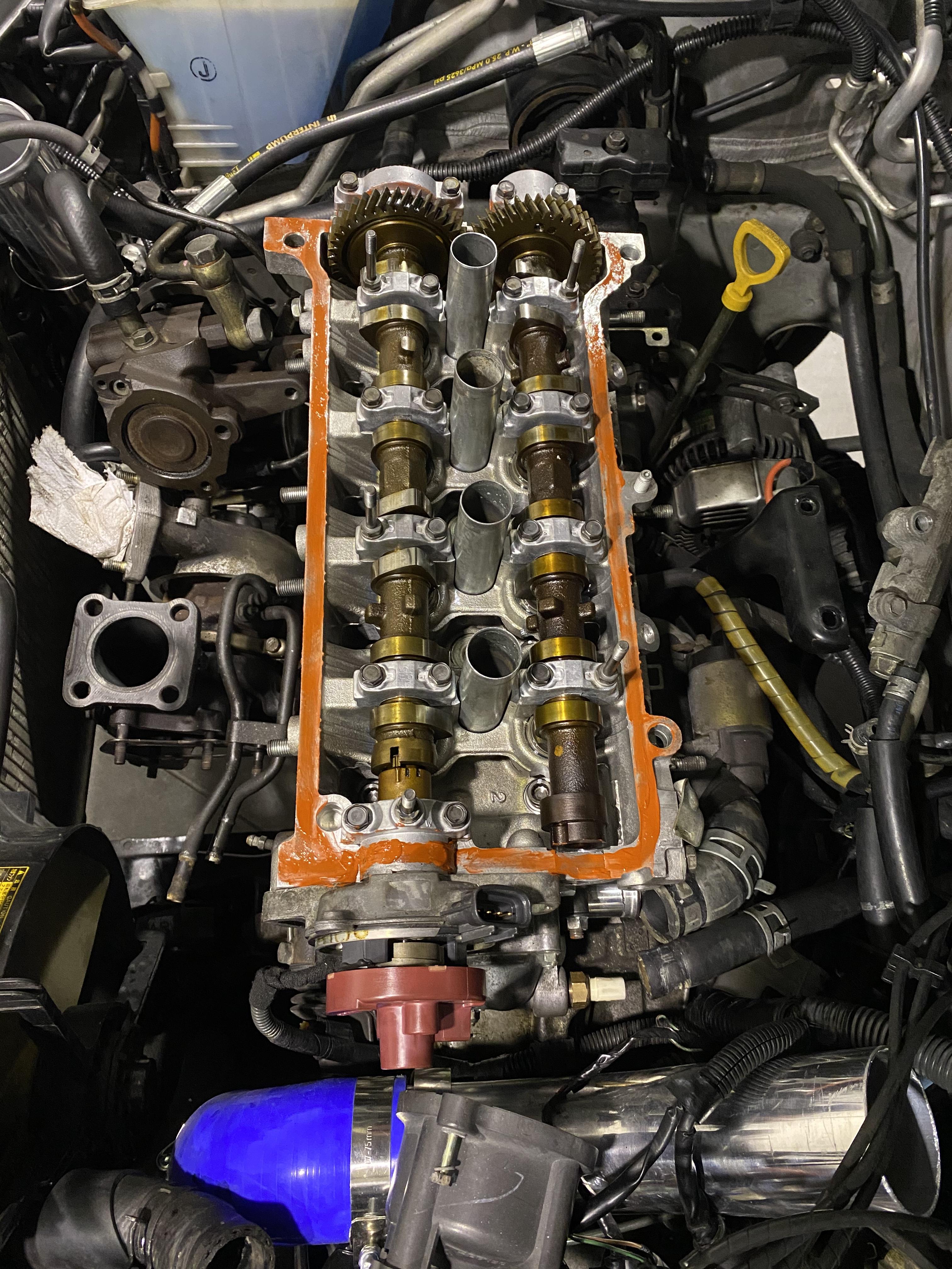
This thread goes way back but the problems to solve are the same. It’s so nice to see many people still loving these cars. I am in the process of solving a valve clearance after forging the head. Rectification has been done and they didn’t do valve clearance for me so I will have to figure it out. The only problem is that I don’t have the shims kit. How do you guys fix the gap when the shims are too thin? In my keys 1/10 mm has been rectified in that valve cup so apparently all shims should be thinner to close the gap. This is essentially theory because I still didn’t check for clearance getting the head cover off. The symptoms are lack of power in mid range and blowing noise that I thought was coming from the turbo. The other symptom is that the engine bangs when changing gear in acceleration. Let me know what you think. Other friends on the forum are already aware of the problem
")
-
16 hours ago, Claymore said:
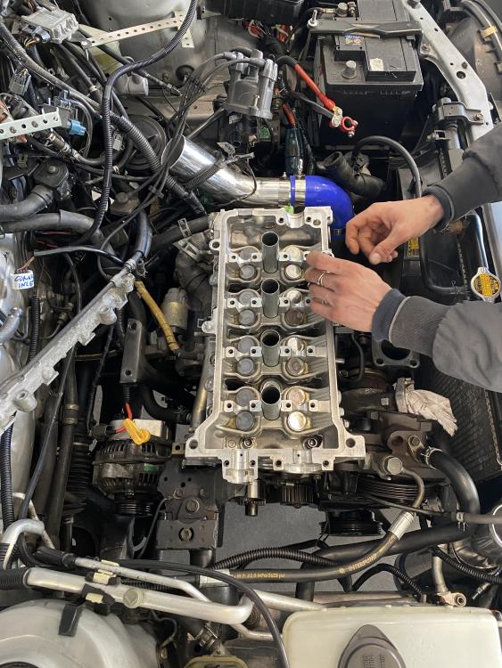
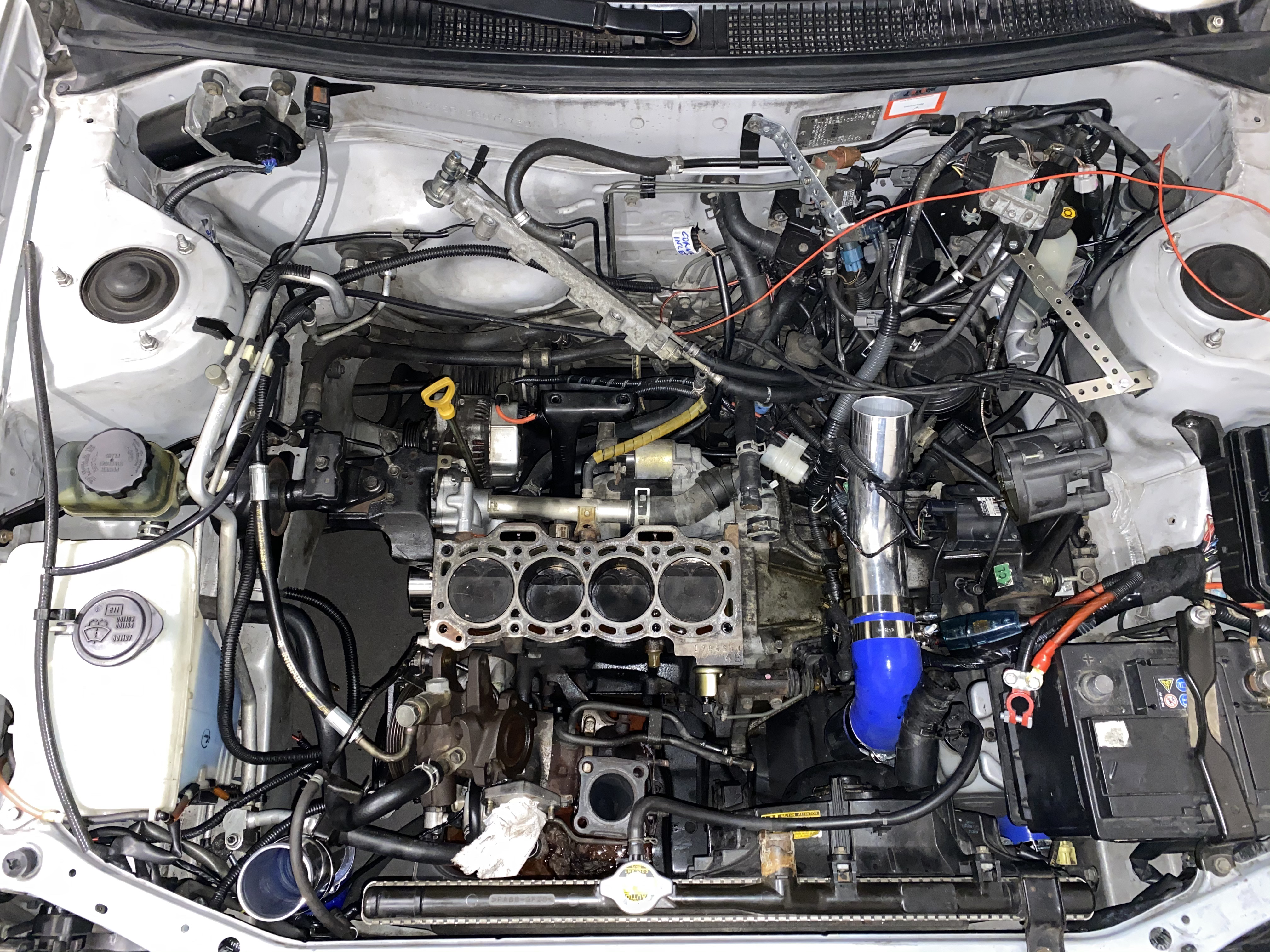
When the cams were installed did you line up the marks on the back of the cam gears correctly (cam to cam)? Is the Timing from the crank to cam still correct? Looks like the distributor was put back in correctly at tdc from your photo.
Yes we checked everything. The turbo is fine because the turbine is smooth and The turbine shaft has no movement. I guess the issue is that the valve clearance hasn’t been checked because the shop doesn’t have the camshaft and I didn’t know I had to do it. Never done this before and I don’t have the specification from Toyota to check clearance between camshaft and cup plates. I am so mad at myself because I didn’t know this and the shop didn’t tell me at all that I had to do it. They said that it’s normal that a mechanic is it gonna check the clearance after ratification but I am not a mechanic and my partner doesn’t have experience with this type of valve movement system without registration.
-
1 hour ago, Sam44 said:
Oh no another machine shop strikes again.
It's so so hard to get good machine done these days.
Really hope you get it sorted and there is no damage to that engine.
My heart is bleeding. They could have explained procedure or just ask me the camshaft in order to do the full job in house. My partner didn’t know the engine and he expected me to know it all. I never went through this process otherwise we would have done it right. I hope there no damage and only tuning needed.
Who has the official Toyota specs for the stock valves clearances with the full procedure?
-
Can you please give me the parameters that the valve gap have to be between?
-
4 hours ago, Claymore said:
Did the valve shims and buckets get removed from the head? If so are the valve clearances correct still?
Here now I just received the truth that apparently seems to be the issue. The valves haven’t been registered. The shop told me that they want to do it without the camshafts. My mechanic didn’t even think about it and put the head back on. I’m so frustrated. I really hope I didn’t bend and evolve or create damage.
-
is it possible that trimming the turbo side of the exhaust manifold would create a noise or change how the turbo CT9 works? Ever since we put the engine back together it is not behaving like before. It’s banging while changing gears and there are holes in the acceleration between 3000 and 3500 RPM. Mechanical timing has been set precise and electric timing has been set as default. What could’ve happened?
-
On 11/4/2020 at 10:22 AM, Claymore said:
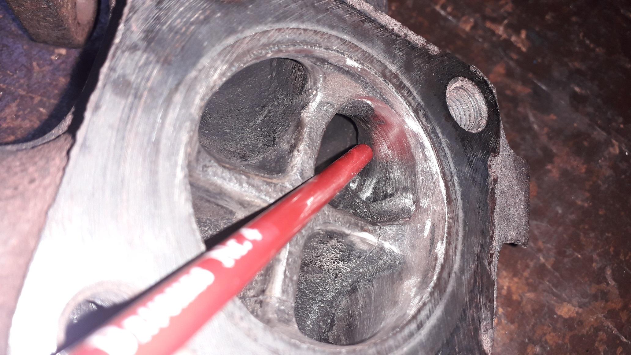
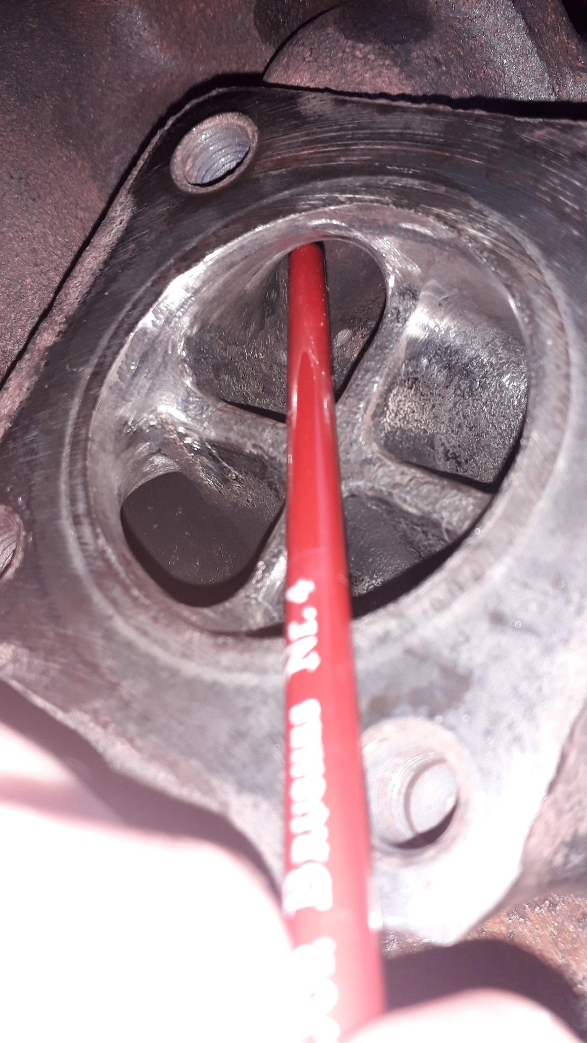
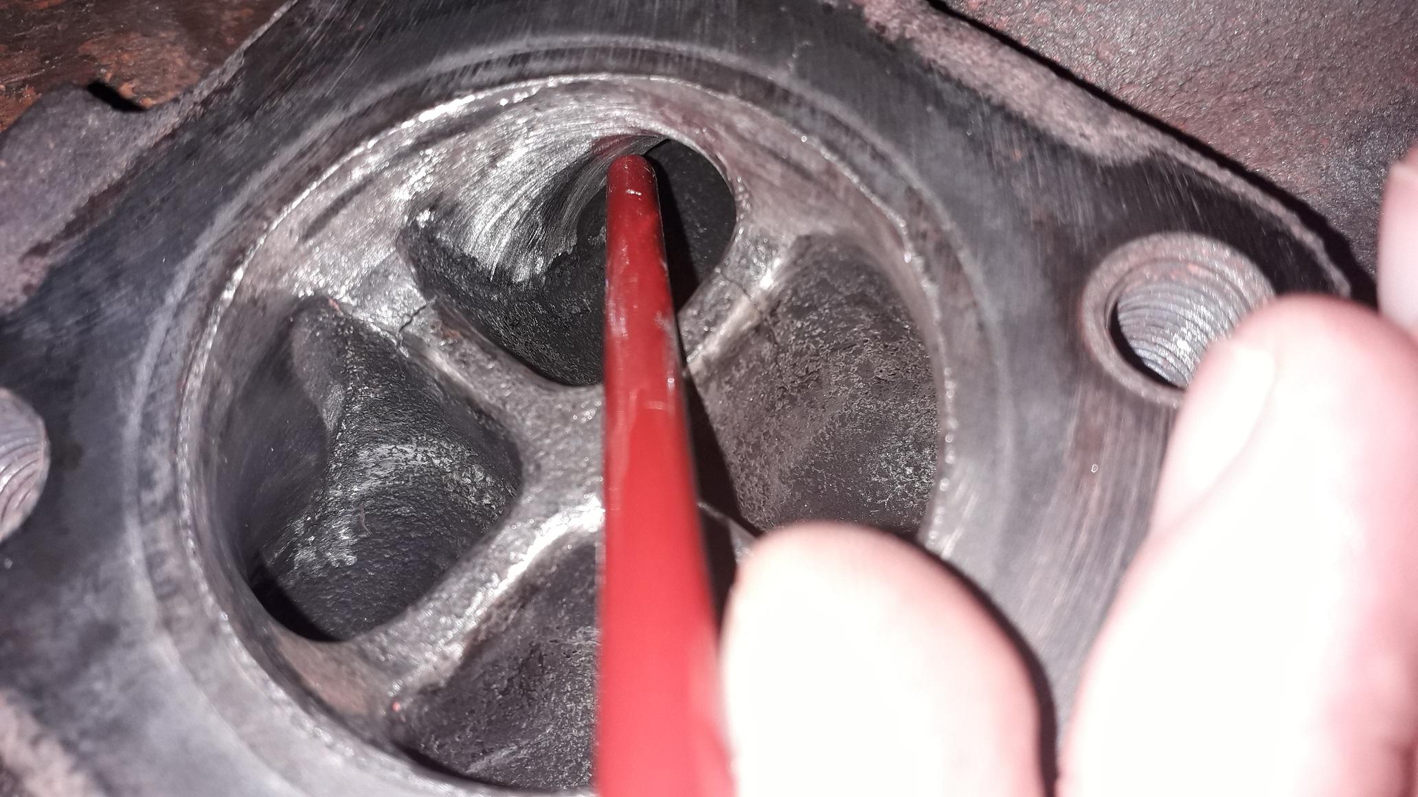
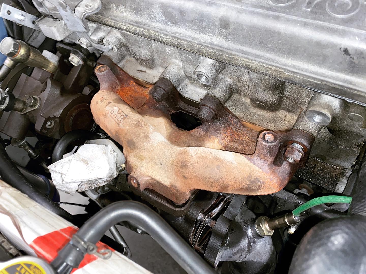
Then I moved on to the main event, the obstructions in runners 2, 3 errrr 1 and 4!
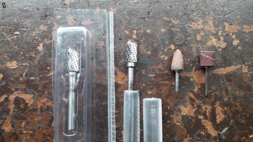
Used an air die grinder with a long and short carbide burr to remove the majority of the material. Size was 10mm diameter x 20mm length round nose. Good size and the round nose is always useful in confined spaces. Grinder for stage 2 and sanding drum to finish.
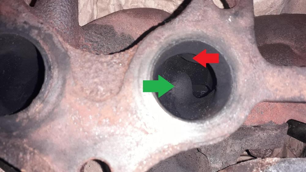
View of no. 3 runner restriction, I removed the green arrow restriction and left the red arrow lump as is because that section of the mani is only approx. 6mm thick.
No. 1 runner had excess material here narrowing the runner. After removal.

No. 2 runner had a lump where the stud is mounted, not as bad as 3 but still needed to be removed. Not easy as you can only see it from the turbo side so had to attack it from both ends. Using the long burr, my best judgment and lots of feeling around I managed to remove the other half of the lump from the head side of the mani. After removal.
No. 3 largest lump under the stud. Easy to remove from both sides with the carbide burr. After removal.
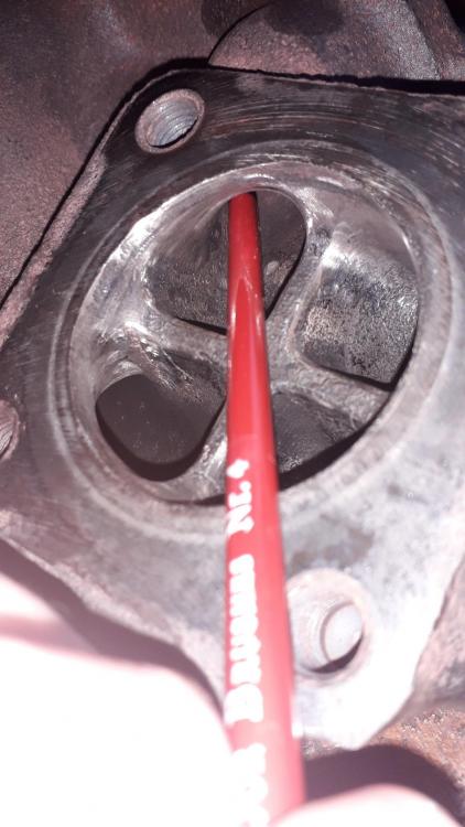
No. 4 runner same as no. 1. Excess material narrowing the runner. After removal.
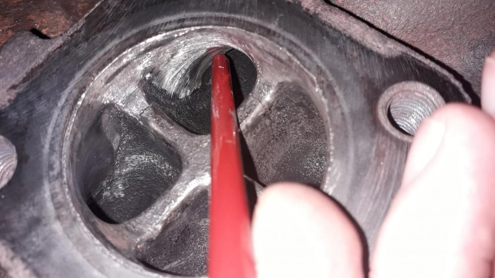
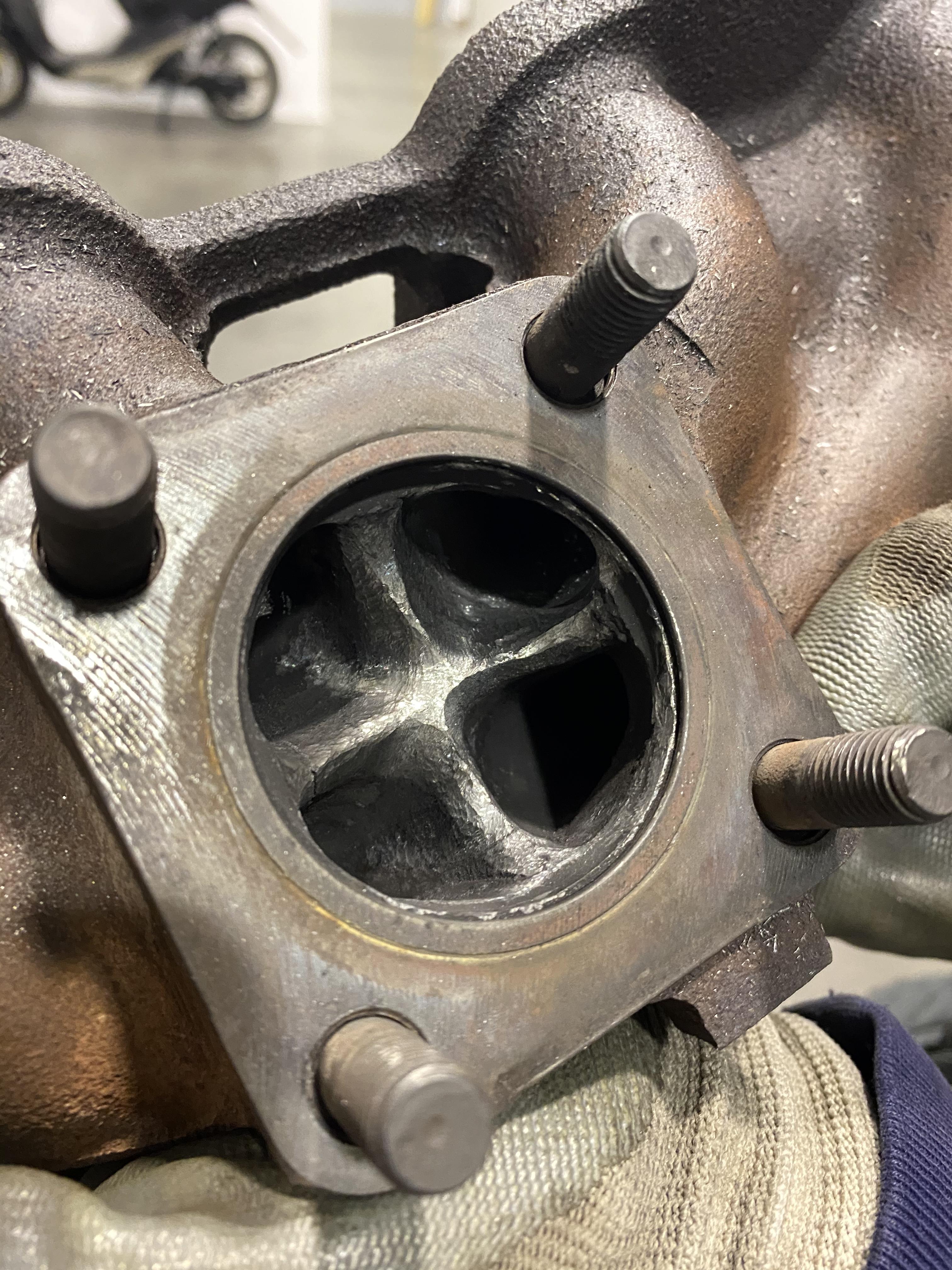
This is what we did we didn’t touch the bolt bumps tho we had to weld two small cracks that are visible in the picture.


-
On 4/17/2011 at 6:55 PM, string said:
high pitched nosies are normally boost leak related. have you checked all ya pipes.
Could this cause loss of power between 3k to4k RPM? The noise I hear feels like air blowing high pitch but my pressure gauge (positioned on the hot pipe) doesn’t show loss of boost. What could it be? We removed the clamp on the efi for convenience purpose and put a screw clamp instead. Yesterday I checked if it was tight enough but it was OK. Also I think that this wouldn’t change the wastegate work in the turbo. I checked the BOV send screwed in a little bit the spring pre-compression I got nothing changed.
-
On 12/30/2021 at 5:39 PM, Claymore said:
The standard 4efte exhaust manifold can be ported by grinding / porting out the restrictions, I did it to one for my build. It will help prevent problems for a small boost increase but not the best option. I also know you don't like to modify rare Toyota parts 😉 (which is fine
 )
)
The CT9 Tubular manifold Tuning Developments sells seems ok as the first upgrade, Hopefully someone using one will comment on its fit and function.
If you want the top level then WEPR make excellent products. But not sure how they will fit in a corolla engine swap vehicle.
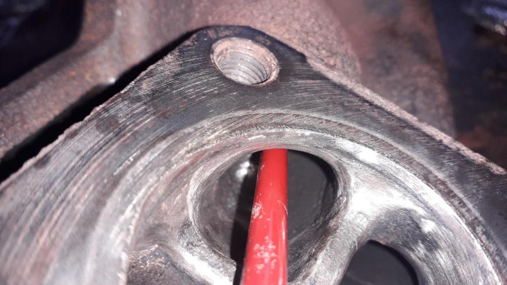
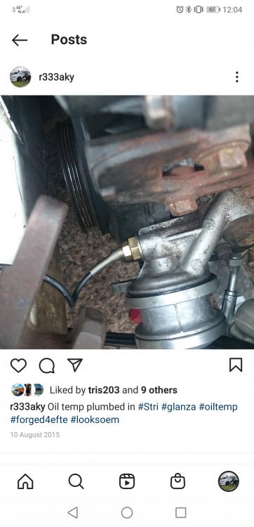
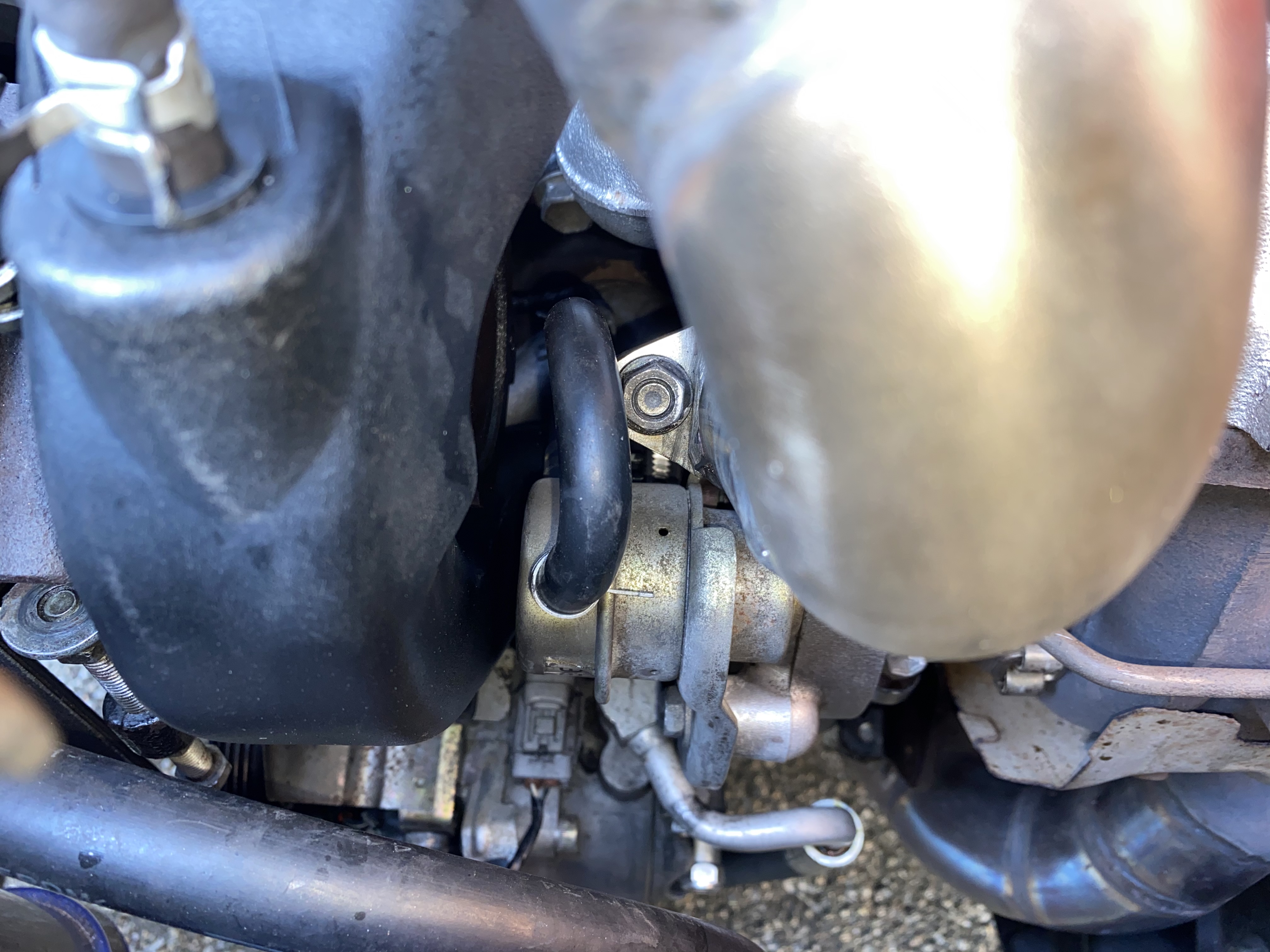
This pipe is where I would weld the fitting for the second boost gauge hose to measure pressure before the intercooler.
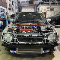
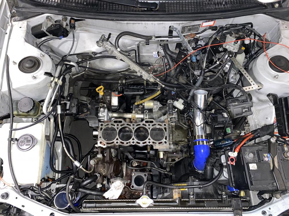
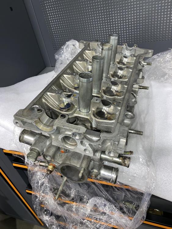
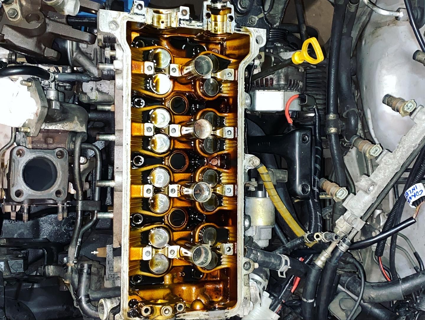
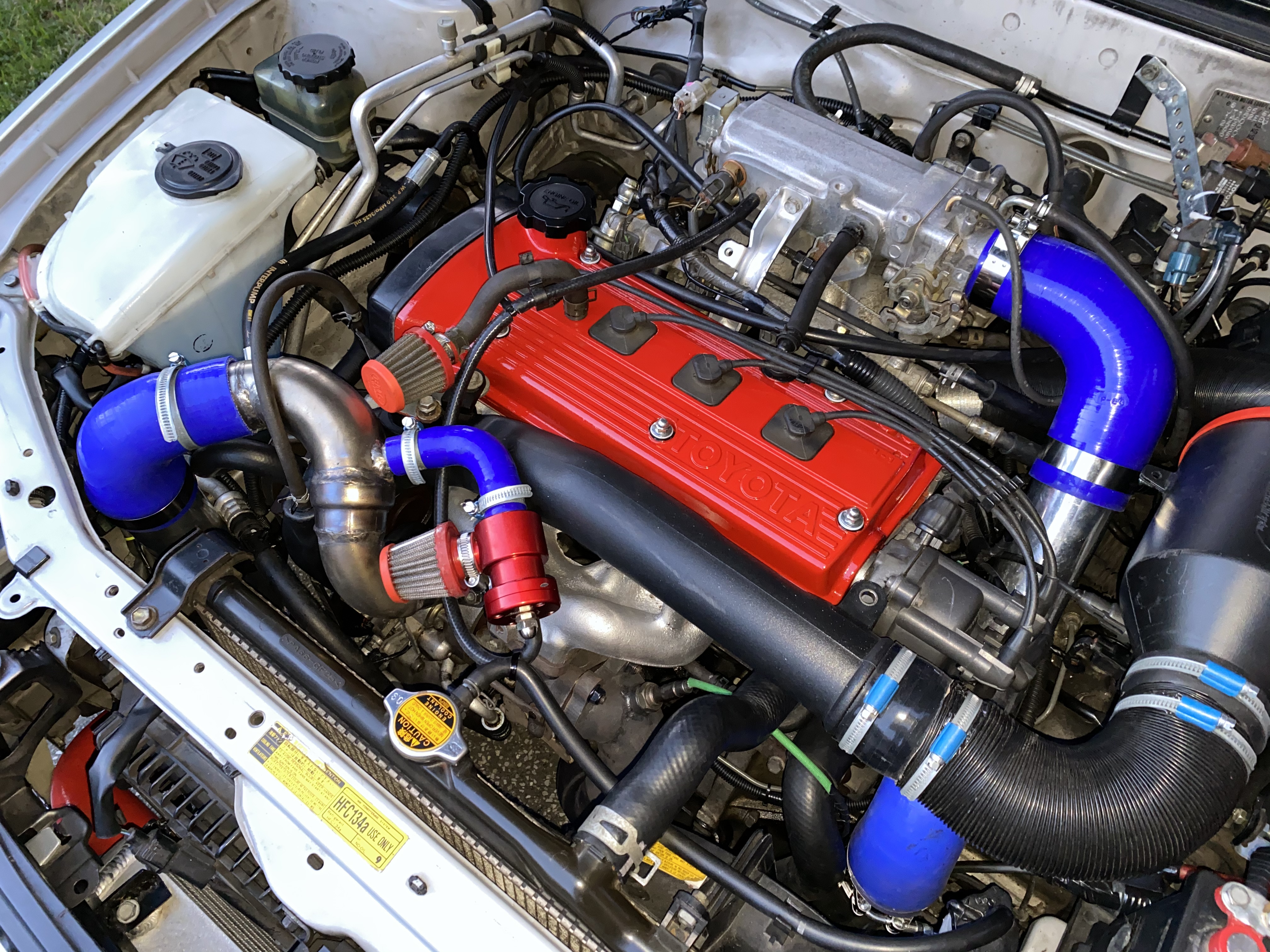
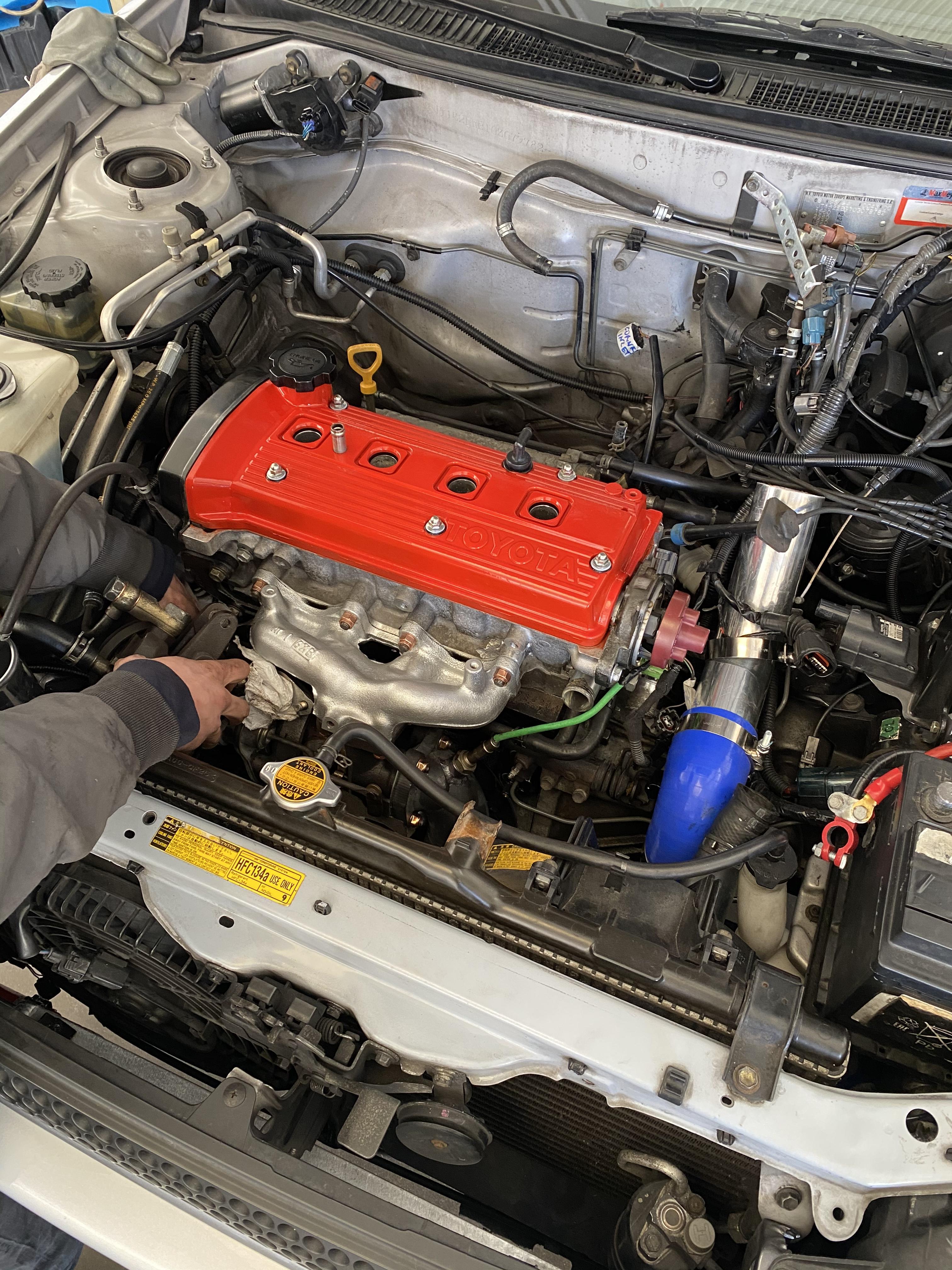
Here is what we did to solve the cylinder crack. We got the head off and sent it to get cleaned. Then sent it to get laser welding. We sent it back to get new valve gaskets on, Valves got cleaned and exhaust and low surfaces got cleaned I got the head back to the shop and cleaned the other parts Luca trimmed and welded a crack in the mani. We painted it and painted the head cover. New gaskets everywhere! New bolts for the cylinder head of course The engine sounds amazing.
But there is a problem! When we first started the engine turbo turbo area was making a squeaking noise. At first thought the oil wasn’t getting to the turbo so the bearing suffered I am not sure about that. How could it suffer after five minutes with the engine on at idle? We fixed the timing in diagnostic mode to set it on 10 it worked fine but I didn’t feel much difference so I put it back to 0 The main issue is the blowing noise like for example the hard intake pipe in the turbo wouldn’t perfectly fit it? Or some silicon hose isn’t properly tight? I checked everything I could and thing is that the turbo isn’t expressing itself how it should and there is a few power drops between 3000 and 4000 RPM I don’t hear a metal bearing noise growing with the RPM I hear constant noise that sounds more like air is blowing from the intake for example? Probably the downpipe? We put new metal gaskets and new bolts and maybe tightened them less than what we should?
What do you guys think?


-
On 7/15/2021 at 1:05 PM, akyakapotter said:
I finally did it and it worked.
-
On 2/7/2022 at 6:38 PM, Sam44 said:
Basically you open out the turbos waste gate port located in the turbos exhaust housing (the little bypass port with a flap/door). What you do is close the door on the port and use spray paint to paint over the top. Now when you open the door fully you can see the edge of the door/flap, as well as see how much the port can be opened out to. You want to leave a 1mm edge so as the door/flap can seal. This is know as porting a waste gate port to stop boost creep
This is some thing I want to try. The spray technique is helpful to understand if the door shots 100%? What is the goal? Shutting 100% or leaving 1 mm open?
-
On 2/7/2022 at 6:38 PM, Sam44 said:
Look into air filter relocation mods on this engine to see how you can go about removing the efi pipe on yours to me you want to go up into the driver's side wheel arch just behind the front bumper, from here you can also get into the engine bay just behind the driver's side front headlamp.
I still need to elaborate this and maybe see some pictures. It’s hard to test on a daily car. I have to be 100% sure that modifications will work. If I haven’t done it before and I have no precise data then I feel uncomfortable trying something new.
-
13 hours ago, Sam44 said:
port the waste gate.
Do you have a description or some pictures of how this has to be done? The boost creep they are talking about worries me. What kind of pipe would I have to replace the EFI with? Silicon? Aluminum? There are many details I am not aware of to do the job before I put the engine back together tomorrow.
-
On 2/3/2017 at 12:07 PM, Starlet__SR said:
Better than the standard though, the port restrictions on 2&3 are an issue.
Hi. I would like to know if I will be able to lower the 2&3 custom exhaust mani restrictions without ruining it. The restrictions are the stud bumps that shouldn't be lowered.
-
On 2/5/2022 at 7:48 PM, Sam44 said:
Yep I will get you one.
The turbo inlet on the compressor housing side.
Sorry to add a link but the insert images button is playing up.
"TOYOTA STARLET GLANZA TURBO EP91 EP82 INLET PIPE | JDM Performance Parts" http://jdmperformanceparts.co.uk/toyota-starlet-glanza-turbo-ep91-ep82-inlet-pipe.html
This pipe is very restrictive.
Once this pipe is removed you will get boost creep.
Info in this topic of how to solve boost creep.
"Porting CT9 wastegate - Intake, Turbo & Exhaust - UK Starlet Owners" https://www.ukstarletowners.com/topic/104815-porting-ct9-wastegate/
You are telling me that I should remove the turbo plastic inlet to have more power but if I do it I will get boost creep. So why should I cause a problem if the ct9 has its own parts studied to be proportioned with the power needed?
so if I get the plastic turbo inlet off, what should I put in the turbo instead?
this is something new to me. If you tell me asap I will do it before I put that plastic inlet back on. Tomorrow we are putting the engine back together. Thanks!
-
18 hours ago, Sam44 said:
It's the turbo inlet pipe, you will see the restriction right at the turbo inlet it narrows, flattens in places and has a few bends all at this point.
Do you have a picture?

-
2 hours ago, Sam44 said:
You might want to port/open out the turbos waste gate port. This will stop boost creep when you decide to remove the efi pipe/turbos induction pipe.
This efi pipe is really quite restrictive on power.
Can u
you please elaborate this? by the way turbo clock cannot be moved. Someone wrote that I could move the hot pipe entrance on the turbo down to be able to reach the rear bolts during disassemble but I doubt that is something you want to do that would compromise turbo clock. Am I wrong or right?


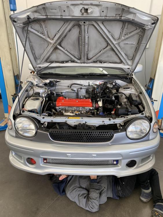
TURBOROLLA (4efe to 4efte ep91) SWAP
in EP91 Progress Blogs
Posted
I’m unable to open the file in italy.