Claymore Posted January 25, 2021 Author Posted January 25, 2021 That's the plan. Seemed to match the smaller turbo / quicker spool characteristics of the ct9 with short runner exhaust manifold. Prefer to rev a petrol engine for power rather than low down torque and breathless top end (great for a daily though). Quote
Sam44 Posted January 25, 2021 Posted January 25, 2021 (edited) totally agreed. you will have a great alround power, and really quite good engine efficiency (nice full power band) with the high torque output were you would want to gear, also helping low rpm traction. with the cam and turbo setup you will get instant spool up. fantastic setup. the e11 corrola inlet does have a sharp power loss just were you dont want it. this tubular manifold with ct9a with a 4efe inlet cam would be a complete mismatch. wheel spin happy, all low to mid rpm torque. as you say. love it great tune. Edited January 25, 2021 by Sam44 Quote
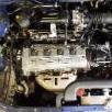
Claymore Posted January 31, 2021 Author Posted January 31, 2021 (edited) Glanza coolant overflow bottle bracket. Need to relocate the current overflow bottle to the passenger side of the engine bay to free up room for air filters etc. So bought a glanza overflow bottle (they never seem to be advertised with the bracket!) which locates there. First job was to move the battery back, the starlet tray has 2 positions available (A / B ) the posts on the underside of the plastic tray locate in the holes. When using the rear position the drivers side hook has to locate in the rear location to clamp at the correct angle. Edited January 31, 2021 by Claymore Quote
Claymore Posted January 31, 2021 Author Posted January 31, 2021 (edited) Time to make the bracket. Started with a piece of scrap alu that was already folded to an L shape. Correct thickness to fit into the pocket on the back of the bottle. Tin snipped, linished and filed to shape. The bottle has 2 rectangular pockets moulded into it to clip onto the bracket. Using a trusty old blunt screwdriver I formed two humps in the plate for this purpose. First on a soft surface and made them deeper by opening the jaws of the vice and tapping the features deeper in the vice gap. Drilled holes for lightness and swaged them for strength. Test fitted to bottle with a nice "snap". After test fitting to the car I cut down the oversized foot section and folded the end 90 degrees to add strength. Then made a U shaped section to be rivet on to add even more strength to the fold of the bracket. Drilled and riveted into place. Painted with acid etch primer (because bare metal / aluminium) and satin black top coat. Edited January 31, 2021 by Claymore Quote
Claymore Posted January 31, 2021 Author Posted January 31, 2021 (edited) Fitting to engine bay. Needed to drill the mounting holes to attach the bracket. So constructed this contraption to add a bit of necessary peril to the proceedings . The holes need to be very close up behind the headlamp so the body of the drill was too large to locate with a regular bit. The bonus of using a step drill is it only penetrates the metal by the depth of the step rather than getting pulled in all the way like a regular bit does. 2 very wobbly hole drillings later...... Fastened down with sheet metal screws, clipped bottle on. Fits well, the mounting holes are oversize to allow any alignment issues to be corrected for. Edited January 31, 2021 by Claymore Quote
RoyalDutchie Posted January 31, 2021 Posted January 31, 2021 Very neat. Good amount of progress lately for sure. Quote
Claymore Posted January 31, 2021 Author Posted January 31, 2021 2 hours ago, RoyalDutchie said: Very neat. Good amount of progress lately for sure. Thanks mate Quote
Pikey009 Posted February 1, 2021 Posted February 1, 2021 Looks great! I’ve literally just one the same thing! Although not quite to the same standard it’s more just to mount it for now and then I’ll be making some tweaks Quote
Claymore Posted February 1, 2021 Author Posted February 1, 2021 35 minutes ago, Pikey009 said: Looks great! I’ve literally just one the same thing! Although not quite to the same standard it’s more just to mount it for now and then I’ll be making some tweaks Thanks mate, Saw your bracket and its nearly there, just needs the humps tapping in to it and a bit of reinforcement at the fold at the bottom. You've done the hard work. Congrats on getting the gt driving, she's looking like a great project. Quote
Pikey009 Posted February 1, 2021 Posted February 1, 2021 (edited) I kind of want to re-do the bracket mate as i'd prefer it to sit the bottle a little higher and the metal is a little thin. At my last workshop I had metal folders etc but there's nothing at my current place. Cheers buddy it is getting there now, I normally only work on it during lunch breaks and the occasional evening inbetween normal work and my degree. Edited February 1, 2021 by Pikey009 Quote
Claymore Posted February 5, 2021 Author Posted February 5, 2021 (edited) 4efte inlet manifold modification. So, with the plate made to fit the fe throttle body to the fte manifold I made some mods to the stock manifold to suit the build better. I won't be needing the IACV hole in the end of the plenum (could be used for a MAP sensor in the future however) So decided to block it off. It's an 11mm diameter hole. Bought an 11mm cup type mild steel core plug. It's an interference fit so needs to be hammered / pressed into place. I softened an appropriate size hex bit socket with masking tape and placed the cap on the end. With the outer surface coated in medium threadlock (just in case it needed help sealing) I hammered it in with a 2kg club hammer. Set in place half way along the hole. Would have preferred a brass version to match the Toyota plug above, but they didn't do one in 11mm. Alternative IACV Blanking plate: https://www.youtube.com/watch?v=tn2yOjUDhZA On the rear of the plenum there are 3 fittings (brake servo, map sensor reference and A/C [I think]) the A/C fitting is 9mm and pretty useless so rather than just block it off I decided to replace it with a barbed hose tail fitting that would suit the piggyback ecu internal map sensor fitting. Removed the old fitting and measured it up. The thread pitch is 28 TPI (turns per inch) and the thread ranges from 9.2 - 9.5mm. The thread pitch and diameter relates to an 1/8" BSPT (British standard pipe taper) thread. So I chose a 3/16" (5mm) barb with a 1/8" BSPT threaded end. Fitting arrived and was promptly shortened by one barb to match the length of the other fittings I applied a small amount of medium threadlock to help seal the root of the threads and screwed the fitting in hand tight. Taper threads in this application don't require a lot of tightening, I have always found anywhere from half, to one full turn will seal perfectly well for low air pressure stuff. Half a turn sufficed and the fitting is in. Now can be used as a dedicated source rather than blanking off and tee-ing into somewhere else. I will be using the fe IAT sensor, so the fte one located in the front of the manifold is also redundant. Upon removal and after measuring it is a m16 x 1.5mm thread. Thankfully this is a common size for drain plugs so.... Drain plug installed with copper crush washer. I installed it to 25Nm as a best guess based on other similar applications recommended figure. Neatens it up and also removes the sensor probe from the inside of the manifold gaining plenum volume as a bonus (approx 1.6cc lol🤣) Edited April 20, 2022 by Claymore Quote
Claymore Posted February 5, 2021 Author Posted February 5, 2021 (edited) 4efte manifold lower bracket. Bought some m 8 x 20 flange head stainless bolts and shortened them to the required m 8 x 12 ish. The bracket is of very generous gauge steel so I also drilled it for lightness and painted satin black. Thankfully the manifold is now ready for install. 💪😃. Still need to mod the throttle cable / bracket but it'll be easier once the manifold is in with the throttle body attached. Edited February 5, 2021 by Claymore Quote
Claymore Posted February 8, 2021 Author Posted February 8, 2021 (edited) ECUmaster DET3+ plug n play harness. https://www.youtube.com/watch?v=dXtzCMs2b6Q Thought I'd make my own pnp harness for the det3 install to save chopping the car loom. Also makes it easier to work on / add connections to it rather than scrabbling around in the footwell.. First, a big thanks to RoyalDutchie and Rob SR at RaceCal Ltd. for their help and guidance. Purchased the necessary wiring loom plugs and the ECU header (socket). They are TE connectors and have 2 different sized receptacle contacts. These are unfortunately only available to buy by the 100. I needed 10 large and 30 ish small 😡 The ECU header is designed for surface mounting so the contacts are 90 degrees to the socket. Thankfully they were tin coated brass and were easy to straighten out. All straightened (Ignore the state of the pliers please) Not all the contacts are used on the starlet so I removed the unnecessary items by pulling the contact out from the "plug in" side (opposite side to shown). This gives more room when soldering the patch wires on later. However it will prevent the potting of the connector as the liquid epoxy would seep through to the plug side. The pins were trimmed down to approx. 15mm. Edited March 24, 2022 by Claymore Quote
Claymore Posted February 8, 2021 Author Posted February 8, 2021 (edited) Moving on to the wiring side of things I needed to make up the required number of patch wires to go from plugs to header. If it was a patch harness all the necessary wires would be installed and then you would cut into them (as if it were the car loom) and then plug it in between the car loom and ECU. It quickly turned into a plug n play loom. The only difference is the intercept wires for MAP sensor and ignition wires are attached directly to the plug and header instead of cutting into a patch wire. This removes some of the connections to improve reliability but will make the harness piggy back specific. Large contacts cut from strip (of 100!!!!). Tails cut off next. Wire stripped Using a W form crimp tool I first squeezed the crimp barrel til the sides were vertical. Inserted into the correct sized jaw. Add wire to barrel and crimp. Then crimp strain relief barrel section closed onto the insulation. Large contacts done. Repeat for small contacts. I took the time to practice crimping some spare wires and terminals to make sure I knew which size jaw to use. I also strain tested the connection to make sure I had learned the correct amount of crimping force required. Each wire was visually inspected and "reasonably" strain tested to ensure it was good to use. Edited March 9, 2022 by Claymore Quote
Claymore Posted February 8, 2021 Author Posted February 8, 2021 (edited) Next I chose the wires I would require and fitted them to the Piggy back ECU plug. I bought the ready made leads with contacts crimped on from ECUmaster to speed up the process. I also loaded the patch wires into the TE plugs, there is a plastic retaining clip to release first, slide wire in (listen for "click" of tab engagement) then close clip. The power and ground needed splicing into the patch wires, so the brass open barrel crimp was loaded into a different pair of "mighty" W crimp pliers. (the light duty ones wouldn't be up to the job) And the part stripped patch harness power wire was crimped to the piggy back power supply. Lots of force required as the pliers were short handled and the splice barrels are very robust. Glue lined heat shrink for added strain relief. Can't solder for shit and didn't fancy learning on this project so I decided to pay my friend (professional electronics engineer) to solder the wires to their corresponding contact. I even got the special old school lead solder as its better than the modern shite. Remember to add heat shrink to wire, prior to soldering. As she stood after soldering. Pleased with the outcome, Tested the harness for continuity and resistance and all was well. If I had to do it over again I would change a couple of things but I'm very pleased with the harness especially as its the first I have made. Edited March 9, 2022 by Claymore Quote
burty Posted February 8, 2021 Posted February 8, 2021 I've said it before and il say it again the effort you put into your thread is mind blowing, threads like this one will be looked back on time and time again for the information/guidance you give out to help others 👏 Quote
Claymore Posted February 9, 2021 Author Posted February 9, 2021 11 hours ago, burty said: I've said it before and il say it again the effort you put into your thread is mind blowing, threads like this one will be looked back on time and time again for the information/guidance you give out to help others 👏 Thanks mate, comments like this really mean a lot. Quote
Claymore Posted February 9, 2021 Author Posted February 9, 2021 Thought I'd add this link here to another thread about the det 3 wiring: Had to splice another couple of wires into the harness I made. Needed to splice the wideband O2 data out ground signal into the sensor ground (not chassis ground) on the ECU. It has to be the sensor ground or there will be an offset in the readout compared to the figure displayed on the gauge. Decided to splice in a length of wire to the harness and attach to that so it would be easier to add more sensor grounds in the future if necessary. Also spliced into the Intake air temp. sensor and connected it to the Piggy back on analogue input #4 so it can be monitored / data logged or even used as a correction factor on the fuelling and timing maps. Quote
RobSR Posted February 10, 2021 Posted February 10, 2021 Nice work on the patch/PnP harness, looks like you’ve done a nice job! It’s worth getting the IAT hooked up for sure also 🙂 Quote
Claymore Posted February 11, 2021 Author Posted February 11, 2021 9 hours ago, RobSR said: Nice work on the patch/PnP harness, looks like you’ve done a nice job! It’s worth getting the IAT hooked up for sure also 🙂 Thanks mate, not a patch on your harnesses (geddit!🤣) but it's a solid first attempt. Would have liked to monitor coolant temps. also but I've runout of inputs 😕. I'm struggling to see the point of the onboard MAP sensor currently as I'll be using the Glanza 2 bar MAP sensor for the modify, load and datalogging signal. The non MAP det 3 would have an extra input which I could have used. Thanks again for the help via PM, it's much appreciated. By the time I'd built it I had learnt alot and I quite enjoyed most aspects, I got quite good at de-pinning connectors as well, but its a learning process. Currently wrestling the setup into the glovebox piggybackbox area. I apologise in advance to the designer at Toyota who worked so hard to package the ECU and wiring all those years ago........ Quote
Dale SR Posted February 12, 2021 Posted February 12, 2021 Amazing the amount of work that's going into your starlet. Love the color of thease ones. Quote
Claymore Posted February 12, 2021 Author Posted February 12, 2021 2 hours ago, Dale SR said: Amazing the amount of work that's going into your starlet. Love the color of thease ones. Thanks mate, appreciate the comment, would love an 8k9 glanza but these seem very rare. Congrats on the new addition to your stable also. Well done for saving another one. Would have been criminal to see that get broken. Quote
Dale SR Posted February 12, 2021 Posted February 12, 2021 3 hours ago, Claymore said: Thanks mate, appreciate the comment, would love an 8k9 glanza but these seem very rare. Congrats on the new addition to your stable also. Well done for saving another one. Would have been criminal to see that get broken. Ye super rare those colours on a Glanza you have the next best thing here though. 👍🏻 Thanks, Ye It really would of been criminal glad I got there in time. Quote
RoyalDutchie Posted February 12, 2021 Posted February 12, 2021 PnP loom looking good and if it does the job I would say it is perfect for what it is right? Looms can set you back quite a bit while the parts aren't too expensive just the amount of hours needed to get it made can add up very quick. Lead solder does solder neat and can flow much better than the new lead free solder, which can be a pain to work with sometimes for sure. Looking forward to the final setup and dyno day always happy to help where I can Quote
Claymore Posted February 13, 2021 Author Posted February 13, 2021 11 hours ago, RoyalDutchie said: PnP loom looking good and if it does the job I would say it is perfect for what it is right? Looms can set you back quite a bit while the parts aren't too expensive just the amount of hours needed to get it made can add up very quick. Lead solder does solder neat and can flow much better than the new lead free solder, which can be a pain to work with sometimes for sure. Looking forward to the final setup and dyno day always happy to help where I can Thanks Dutchie, totally agree on the loom, parts are cheap but it took a few days to get it made that's why these looms sell for the price they do, man hours to design and make. I also had to buy 100 of each contact and splice (only used less than half including trial crimps) and needed to buy 2 pairs of different crimping pliers as I didn't have the specific ones for this type of work. But I learned a lot and no longer fear that side of things. The Haltech you tube channel has some great info regarding loom making etc well worth a look if you like that stuff. The road tax is about to run out, so I can take it off the road and the fun part of the build starts very soon.... Quote

Recommended Posts
Join the conversation
You can post now and register later. If you have an account, sign in now to post with your account.