Stu Posted January 30, 2014 Author Posted January 30, 2014 Few photos from the gearbox work: Ages ago I threw a litre of oil into the gearbox and found there was a really small but incredibly annoying slow leak. I had been avoiding fixing it and being lazy I was harassing my younger brother Ryan to pull the gearbox out and fix it for me, which he actually did as a Christmas present (rad). Was so un-motivated to do it so stoked he did. It was luck that I had only put a litre of normal gearbox fluid in to check for leaks before putting the redline stuff in or it would have been a waste. Anyway, the below is mainly all Ryans good work, I was just the cleaning and passing tools guy which was awesomeRipped the box out leaving the engine in place, stripped it down. I gave the casings a paint strip/wire brush as the original black paint was a bit crappy.When I originally built this combo I only had an auto dust cover so took the opportunity to make a patch and cover hole. Didn't take any finished photos.Gave the everything a once overAlso double checked the diff preload, spot on stillThen back togetherAnd then hit it with some engine paint, hides the sins...So I then refitted the box etc. Quote
morgey Posted January 30, 2014 Posted January 30, 2014 Great work as usual dude!Can you explain what/how you check the diff preload. What is it you are looking for, as this is something I should really do before swapping my lsd's back over! Quote
Stu Posted January 30, 2014 Author Posted January 30, 2014 Thanks dude, more to come shortly, just waiting till I finish it before posting. The diff preload sets the breakaway torque ie the amount of slip required for the LSD to lock up. You don't want this to be too slack or you will get alot of one wheeling going on. The less torque the slower it will be to lock up, the more and it'll be quicker. You have to be carefull with diffs to get it right as if its too tight it can make the car a bitch to drive around corners at slow speeds - especially front wheel drives. And pays to always make sure its not set to 2way or it'll lock up on decel which in a fwd if it happens into corners at speed is all bad (ie no steering). I tend to not let them get down below 45 ftlbs but its each to their own preferences really. To test I use the inner cv's (one with a nut welded to it), a vise and a good torque wrench. The diff will slip to start then as more torque is applied it will lock up. A good digital wrench will give you the reading but even a basic dial wrench you can work it out by dialling more in to find the point of slip, then start say 10 ftlb higher and work back so you can find the range. If its really slack then you should pull it down and check to see if the clutch plates are abnormally worn in which case just buy a new clutch pack from Toyota, or you might get away with fitting a thicker shim. Dependant on how fussy you are (I was) you can work out the preload by taking the shim out and a soft metal coil (like solder) and reassemble. Then measure the amount of compression with some verniers and work out the shim size that way. Double check after by using the torque wrench. There's also the diff bearing preload exerted onto the carrier bearings once the cases are squeezed together. Measure this the same way by assembling using solder instead of the shim and measure for the correct shim size. Usually this is ok unless your putting new bearings in. Quote
morgey Posted January 30, 2014 Posted January 30, 2014 sound, cheers for that. ill do this to the cusco thats fitted when i remove it as im pretty sure that its not how it should be, will be better knowing what im selling if its been set up! do you know if the OEM helical diff cam be set like this or is that a fixed unit? Quote
Stu Posted January 30, 2014 Author Posted January 30, 2014 I believe that they are fixed - its one of the reasons why I like the clutch pack type LSD as you can set them up the way you want Quote
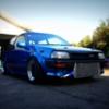
Stu Posted March 16, 2014 Author Posted March 16, 2014 Not alot has been happening I'm afraid - we are buying a new house so have been spending most available time making touch ups on our current place. The rear turrets are all done now and I've trimmed and refitted the plastic interior covers - looks good. Will take some photos when I get a chance later this week. For now just a quick photo of the rear. There is plenty of height adjustment still available but may need to make adjustable arms to push the wheels back 20mm or so. Not a priority now anyway, will raise it up to a respectable height and focus on other stuff. Quote
Stu Posted May 2, 2014 Author Posted May 2, 2014 Rolled it out of the garage today while packing to move house - sooooo want to be working on it but that is having to wait till we are into our new house (next Friday) /useless update Quote
mccartney11 Posted May 30, 2014 Posted May 30, 2014 (edited) any videos of this beast?!!! fair play for the work, can i ask why you wanted to go up a tyre size, but then modified the rear mounts to lower it more? Edited May 30, 2014 by mccartney11 Quote
Stu Posted June 9, 2014 Author Posted June 9, 2014 Sorry there isn't any videos - its winter here but come this summer i'll be getting it out to a few track days etc and will get some then. I think there might be an old drag racing youtube clips around from Meremere but its probably 7-8 years old now Re the tyre sizes, I've got several sets of wheels for the car but with the 14inch equips I really wanted a snug fitment. The 45 series tyres were awesome but the overall tyre height meant the car had very little road clearance but still had a huge amount of wheel to guard gap which wasn't what I was going for. The 55's provided a taller overall height and meant that I could lower the car down to close up the guard wheel gap. Quote
littlegreenmonster Posted August 8, 2014 Posted August 8, 2014 Man please update this !!!! Really wanna see how it goes !! Quote
Stu Posted August 11, 2014 Author Posted August 11, 2014 Shit had forgotten about this- sorry . ' Well I've been working on ALOT of other cars recently which has meant I haven't done much till just last week when I got back into it. I've been working on the inlet manifold again mounting the antilag/idle up solinoid. I've sent my injectors off for a check up and ordered a whole heap of other parts for the fuel setup. Once the inlet and fuel side is together its wire up time - not alot left after that. Here's a few pics from the other week: More updates soon Quote
littlegreenmonster Posted August 11, 2014 Posted August 11, 2014 Thank god !!! Ive been waiting flr these for ages you bugger !! Quote
littlegreenmonster Posted August 12, 2014 Posted August 12, 2014 Hahaha you will be if i ever see you !!! just kidding, she is looking mint matey Quote
Stu Posted August 12, 2014 Author Posted August 12, 2014 Thanks! I've got a few new parts turning up this week so will update soon. The goal is to have it running again before Christmas Quote
littlegreenmonster Posted August 17, 2014 Posted August 17, 2014 Ahhhh i see well good luck with that buddy i look forward to progress (but dont forget this time) ;) Quote
Stu Posted August 25, 2014 Author Posted August 25, 2014 (edited) No photos from my car but Morgey will be glad to know I've finished and tuned the EP82 now - hopefully onto the dyno this week to see how much power it isn't making... My car wise, fuel reg and gauge is here, I've machined the fuel rail extrusion, bought some fittings. Need to do some finishing work on the inlet then I can mount the rail and plumb it up. Edited August 25, 2014 by Stu Quote
Stu Posted September 3, 2014 Author Posted September 3, 2014 So have shifted back to working on the engine again. I hadn't quite finished off the inlet manifold so I spent a few hours with the dremel cleaning up the welds around the injector ports inside the runners. Shaped them all with the carbide bit so they looked like the above then swapped the bit to a sanding drum and tidied them up. Also welded a plate onto the underside and drill and tapped the NPT hose fittings for the brake booster and vac line take offs. Then finalised the mounting of the idle speed controller. This is a two wire PWM bosch unit and will be controlled via the link to handle cold start idle up and load rpm adjustments (for headlight/alternator load etc) along with being the air bypass for antilag. I ran a similar setup on the old engine via the old Linkplus but with the G4+ the control is quite alot nicer. I wont have any of the issues of un-even idle or difficult starting that I'd seen with quite a few customers cars that have come thru. Should be able to adjust idle quite accurately and also have progressive warm up idle speed adjustment like factory. Here's a photo of the old setup - will retain the same bypass piping to the intercooler pipe.I was never very happy with using a stock 4age fuel rail as it had an extra mount that I wasn't going to use and the top mount reg and feed which I was going to have to fill and machine back.So, I bought some Aeroflow fuel rail extrusion and started to make my own fuel rail. I was thinking about centre feeding this with returns from both ends hooking down to the fuel pressure reg that I would mount under the inlet somewhere but in the end I decided this was overkill and end feeding was fine.Stock railAeroflow extrusionChopped then rail to length, then used the milling machine to drill holes for the M5 mounting bolts. Then used a 10mm milling bit to recess the cap screws into the rail so the heads sit flush - trying to make it look tidy.Reamed the ends to allow the aeroflow -6 weld on fitting to slide inside the railThen welded them onSo it looks like thisCopied across and drilled the injector portsSat it all in place and measured up the spacers needed to bolt the rail to the inlet (already had tabs between the runners from fitting the stock rail). You can see the throttle cable bracket welded under the plenum, you can hardly see the cable so its quite tidy. Still need to trim the length of the idle speed controllers bypass hose.You can see the idle speed controller under the inletChopped the fuel rail spacers then drilled/tapped each end and fitted them. The rail is rock solid - fingers crossed there are no leaks. I've started buying the fuel rail fittings but need to mount the fuel pressure reg before finalizing the final fittings and pipe I need. Will be using stock piping from the 044 pump to the fuel filter on the fire wall, then -6 fittings and line from there to the rail > reg > return. If I looks like the stock fuel line will be a restriction then I'll change it but I'm hoping to get away with it.So this is where its at now. Next is mount the fuel reg, fit the fuel pressure sensor for the Link, and make up the lines - then the fueling side is all done. I've started to design the mount for the HEC715 coils, just need to decided on the final spot (somewhere over the gearbox probably) and the Link ignitor mounting location. Will mount the coils like this probably. Quote
Stu Posted September 3, 2014 Author Posted September 3, 2014 Oh, forgot to add, I had the injectors for Garreths car tested the other week prior to tuning so this week I took mine down for the same treatment. Im using some 760cc Siemens units which should do the trick. Here's a photo of Garreths getting flow tested - didn't get a photo of mine being done as I just dropped them off this time. Money well spent making sure they're spot on. Quote
Clinternational Posted September 3, 2014 Posted September 3, 2014 Awesome goodies and skills you got there very nice!!! Did you thought on using not only 4 but 8 injectors ? Twin system ? Quote
Stu Posted September 3, 2014 Author Posted September 3, 2014 Thanks dude. Yeah I have and my ecu will run 8 injectors sequentially so I can still run antilag and sequential idle etc but there isnt much point in running 8 as I can just buy bigger injectors if I need them. Im running a 044 pump so there shouldnt be any reason I wiuld run out of fuel. I wont be running it on e85 so 760s ahould be heaps. Staged sequential setupa just seem overly complicated for not much advantage to me. Quote
Stu Posted September 29, 2014 Author Posted September 29, 2014 Shit/boring update but still heading in the right direction. Inlet is all on for the final time I hope. Just before I refitted it I took the opportunity to replace the clutch master. Obligatory photoWasn't going to use the standard reservoir so took that off and welded up the fitting so I could drill and tap it to suit a 1/8NPT elbow fitting. It got nice and toasty when I welded it.Some matte black paint to make it looks less shitDoneI hate engine conversions that don't have heater hoses - seems such a cop out to not sort them out. The stock EP71 heater lines run via a control valve mounted on a bracket high on the firewall - its pretty gay. In my case it hits the intercooler pipe and throttle body. The stock control valve is a right angle which is a right pain in the vag but I managed to find a straight unit from pick a part so made a bracket off the gearbox and made up some lines from bits of pipe I had laying around. Also moved the control cable which was by far the shittiest job lately - needed to take the heater box out etc. Anyway, photos as you all hate text I can tell...Stock heater lines can just be seen kindaAnd here's my versionHave also done quite a bit on the coils, but no photos /lazy Quote
morgey Posted September 29, 2014 Posted September 29, 2014 Good to see you're still making progress with this. That floating clutch reservoir is pretty handy, could do with doing that to mine! Quote
Clinternational Posted September 29, 2014 Posted September 29, 2014 Looks very clean and tidy! I've also removed that weird gay ass heater pipe control.Don't know what function it have. P8 and P9 doesn't have such a thing.I think it's to block hot water going thru the firewall into the heat exchanger ?? P7 and P8 clutchmaster are exchangeable. P7 stock ones are most of the time leaky. Quote
Stu Posted September 29, 2014 Author Posted September 29, 2014 (edited) It stops hot water entering the heater core, ie controls the heater temp and is something I definitely wanted to work. Later model starlets are electronically controlled with the valve inside the firewall. If you dont have the valve your heater will be hot all the time.Yes this is a EP91 clutch master; direct fit.Thanks Morgey, ive had a break in other work so getting into mine for a change. Have done quite a bit lately. If all goes to plan I will be wiring this shortly Edited September 29, 2014 by Stu Quote

Recommended Posts
Join the conversation
You can post now and register later. If you have an account, sign in now to post with your account.