

vizzioarts
-
Posts
316 -
Joined
-
Last visited
Content Type
Profiles
Forums
Wiki
Media Demo
Events
Everything posted by vizzioarts
-
I know the feeling. Took me all in about 4 hours too. Threw everything I had at them haha!
-
Congrats on the strips! Haha what method did you end up using to get rid of the adhesive? Car looks well now! Very tidy!
-
Clock Conversion : Starlet n/a to Starlet SR cluster.
vizzioarts replied to vizzioarts's topic in Tutorials & Guides
As noel said. Trace it yourself. Not 100% sure why the rpm doesn't work. Hopefully Chris can give you the photos to help. -
Welcome!
-
Vizzio's EP91 n/a Starlet Progress - Update: 04/06/15
vizzioarts replied to vizzioarts's topic in EP91 Progress Blogs
Haha yeah. The student life is holding back funds too. -
Vizzio's EP91 n/a Starlet Progress - Update: 04/06/15
vizzioarts replied to vizzioarts's topic in EP91 Progress Blogs
Cheers! Finally getting the ball rolling with this again. Been slacking over the past few months. -
Looks good! Grids look mint. And the 98 spec lights will tidy it up.
-
Vizzio's EP91 n/a Starlet Progress - Update: 04/06/15
vizzioarts replied to vizzioarts's topic in EP91 Progress Blogs
UPDATE: Long awaited update. Purchased some mint reflet tail-lights from @monty1991. After some messing about with the n/a loom, purchasing a few bits and pieces for them, got the reflet tail-lights fitted this-morning: -Chris -
My bright green starlet N/A update *lock please*
vizzioarts replied to JDMfreak's topic in EP91 Progress Blogs
In my case (and i think most) the signal is already wired into the n/a loom for the cluster. The rewiring just seems to be to reconnect the other connections (warning lights etc) -
Clock Conversion : Starlet n/a to Starlet SR cluster.
vizzioarts replied to vizzioarts's topic in Tutorials & Guides
Yep. That's the idea. -
Haha that was quick. All the best with it!
-
Aye fair enough. Costs me £50/month for the train. I Couldn't run the car for double that.
-
I Wouldn't be driving anywhere near that city Centre around rush hour. Train no good to you? I get it down to Queens every day, wouldn't look back haha. (Feel like a translink advertisement!) Lol
-
Vizzio's EP91 n/a Starlet Progress - Update: 04/06/15
vizzioarts replied to vizzioarts's topic in EP91 Progress Blogs
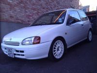
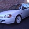
Been seriously slacking on this Got a few updates coming very soon including: - Reflet Tail-lights - Glanza intake mani fitted - Rocker cover painted up Other upgrades in mind - Glanza interior - Colour code mirrors. - Wheel refurb Just need to find the time, especially on the engine work as the car is my daily, and cant really afford to take it off the road for a few days. Updates Coming Soon! EDIT: Also love this pic from a recent meet in September, taken by @JayStar77 -
My bright green starlet N/A update *lock please*
vizzioarts replied to JDMfreak's topic in EP91 Progress Blogs
Need to get that electric window conversion done soon myself tbh. Hope the guide works out alright for the clocks, any problems give me a shout -
Great read and an awesome amount of work! Really enjoy looking for future updates
-
as Chris said. 40mm drop with 195/50/15's are the way to go..
-
PM'd
-
Welcome to UKSO
-
Clock Conversion : Starlet n/a to Starlet SR cluster.
vizzioarts replied to vizzioarts's topic in Tutorials & Guides
Haven't had a look at paseo clocks. Although they shouldn't be far off. If they don't work, draw up a table and trace the lines on the circuit board and find out what everything does. Good Luck -
Clock Conversion : Starlet n/a to Starlet SR cluster.
vizzioarts replied to vizzioarts's topic in Tutorials & Guides
In hindsight it should have been explained better by myself. The wiring tables are the dials circuit boards. Therefore if you trace the wiring on the back of the dials, each pin will correspond to that function on the clocks. The two dial circuits are wired slightly differently. The pictures are just a reference to show my wiring before i moved any of them (reference for myself too, to put it back to standard). In theory, if your module wiring looks identical the ones in the picture it will work. And yes sorry, the modules seem to be flipped in these pictures. i.e. C5 to C6 will be the brown and white wire, to the empty space beside it. Hope this helps, any other questions just ask -
id say ill be there fairly early. 11.30-12 ish.
-
Got notice from Chris earlier ^^ I should be down to spectate with +1. see you there! - Chris.
-
Welcome along
-
Land Rover Defender 110 - WARNING EXTREME ARCH GAP
vizzioarts replied to Chris Green's topic in Other Motors Progress Blogs
That green looks well, something different Menacing looking unit!