

Taggy
-
Posts
2479 -
Joined
-
Last visited
Content Type
Profiles
Forums
Wiki
Media Demo
Events
Everything posted by Taggy
-
 Ok got some trivia for you which will help me at work, basically i get paid a car fuel allowance in work per mile i travel, now i get paid hell of alot more if my car is 2000cc+ the problem is that the basdards in work dont class my 2.0Litre petrol Clio sport as a 2.0l as it has an engine capacity of 1998cc, WANKERS!! Anyway i need to know what cars have 2000cc+ which are petrol, i am going to change my bloody car if i have to as the payments are nearly half otherwise. So come on then post up, cheap to buy also is a plus point!!
 -
cheers dude
-
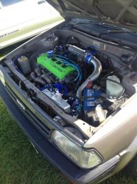
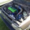
Josh made up some stickers for me the other day for my engine build so thanks to him for his handy work, , just replaced the original 5efe sticker with a 5EFTE Hybrid sticker and also in carbon fibre a "Built by Taggy" and the date, so if i ever sell it on will be good to have a history on it so i can follow where it goes and i also decided to brighten up my fuel cell as it was boring black
-
With Regret... My New Cam Cover #OFFERS??
Taggy replied to StarletMad's topic in Starlet Parts For Sale
ooooo that is nice -
I have tracked a TD04 to death on the starlet with no water lines and have never had any problems, what I did have problems with which is what prompted me to do it after bit of research was when i cooked my engine on track with the lines attached. The rad system on the starlet is quite small and high temp track use boiled my coolant and i spun a bottom end bearing, bloody starlets have no warning system when its overheating and i missed the guage poiting into the red in the heat of racing an evo lol!! I do have mine attached at the moment as my new turbo came with lines but if i went on track i would block them off, its just an extra heat source into the rad system you could do without.
-
.
-
Josh@TunerLifestyle's Project Glanza *20/06/14*
Taggy replied to Josh@TunerLifestyle's topic in EP91 Glanza Progress Blogs
lolz i wasnt expecting the pink! -
No they are both the same and will swap no problem
-
ah just as well i left it in then
-
Yeah i wil cut it out and see if it helps The ignition wiring isnt as bad as it originally looks, if you check on the back of the ignition plug there are codes stamped onto the female section of the plug, they match up between both cars but are in different pin positions so you will have to do some creative wiring, failing that just copy the colour codes i have soldered together
-
How to build a forged 5efte engine - step by step guide
Taggy replied to Taggy's topic in Tutorials & Guides
Yeah i will see if i can find someone whos covered it already -
How to build a forged 5efte engine - step by step guide
Taggy replied to Taggy's topic in Tutorials & Guides
I am just tidying it up to move into the how to section for some reason some of the pics have just started fucking up hmmm -
Taggys Dummies guide to building a forged 4e / 5e fte engine (same applies for stock engine) How to build a 5E - FTE engine from scratch Index Introduction Parts required Machine shop work Tolerances on critical engine parts Bottom end assembly Introduction So you consider your self a dummy but are keen to build engines and save your self some wonga, then read on. With this guide anyone should be able to build an engine who can follow my instuctions. Its not a black art and is actually fairly easy. Most of it is just knowing the correct procedure for everything I am documenting this on my own forged 5E build Now UKSC managed to loose my disasembly guide to go with this so this will currently just cover the reassembly, I'll rewrite it after i have put my engine back together! Note everything in here is for reference and I take no responsibility for anything in building your own engine and stuff going wrong, but follow this correctly and you will be fine. TAKE NOTE! So first rule of thumb in engine building, DO IT ONCE, DO IT RIGHT!!!!! Dont cut ANY corners and read this document about 10 times before you even start building it so you are familure with the build process. If you cut any of the steps out or rush building it, you may as well throw your money down the pan. Engine building is all about minute tollerances between parts and putting everything back together in a set sequence, thats the pep talk over, let go!! 5E Torque specifications TORQUE SPECIFICATIONS TABLE Application Ft.Lbs.(N.m) Accessory Drive Belt Pulley Bolt ................. 14 (19) A/C Compressor Bolt .............................. 18 (24) A/C Compressor Mounting Bracket Bolt ............. 20 (27) A/C Idler Pulley Bolt 12-mm Bolt ...................................... 20 (27) 14-mm Bolt ...................................... 27 (37) Axle Shaft Nut ................................. 159 (216) Ball Joint-To-Lower Control Arm Bolt/Nut ......... 59 (80) Camshaft Sprocket Bolt ........................... 37 (51) Connecting Rod Nut ............................... 29 (39) Coolant Housing Bolt/Nut ......................... 13 (18) Crankshaft Pulley Bolt ......................... 112 (152) Cylinder Head Bolt (1) Step 1 .......................................... 33 (45) Step 2 ............................ Additional 90 Degrees Delivery Pipe Bolt ............................... 14 (19) Distributor Hold-Down Bolt ....................... 13 (18) EGR Pipe Nut ............................................. 22 (30) Union Nut ....................................... 29 (39) EGR Temperature Sensor ........................... 15 (20) EGR Valve Nut .................................... 13 (18) Engine Mount Left (Transaxle Side) Bracket-To-Mount Insulator Bolt ................. 35 (47) Bracket-To-Transaxle Bolt ....................... 47 (64) Rear (Firewall Side) Bracket-To-Transaxle Bolt ....................... 35 (47) Through-Bolt .................................... 47 (64) Right (Timing Belt Side) Mount-To-Cylinder Block Bolt/Nut ................ 47 (64) Through-Bolt .................................... 54 (73) Exhaust Manifold Nut ............................. 35 (47) Exhaust Pipe Support Bracket Bolt ................ 14 (19) Exhaust Pipe-To-Exhaust Manifold Nut ............. 46 (62) Flywheel/Drive Plate Bolt ........................ 65 (88) Fuel Line Banjo Bolt ............................. 22 (30) Idler Pulley Bolt No. 1 Idler Pulley .............................. 13 (18) No. 2 Idler Pulley .............................. 20 (27) Intake Manifold Bolt/Nut ......................... 14 (19) Intake Manifold Brace Bolt/Nut ................... 15 (20) Main Bearing Cap Bolt (2) ........................ 42 (57) Oil Pump Drive Sprocket Nut ...................... 27 (37) Power Steering Pump Adjusting Bracket Bolt ....... 15 (20) Power Steering Pump Bolt Lower Bolt ...................................... 29 (39) Upper Bolt ...................................... 32 (43) Pressure Regulator Valve ......................... 22 (30) Spark Plug ....................................... 13 (18) Throttle Body Bolt/Nut ........................... 14 (19) Tie Rod Nut ...................................... 36 (49) Torque Converter Bolt ............................ 18 (24) Water Pump Bolt/Nut .............................. 13 (18) Wheel Lug Nut ................................... 76 (103) INCH Lbs. (N.m) Air Control Valve Bolt .......................... 69 (7. Air Pipe Bolt ................................... 48 (5.4) Camshaft Bearing Cap Bolt (3) ................. 115 (13.0) Clutch Release Cylinder Bolt .................. 106 (12.0) Coolant Inlet Pipe Bolt ......................... 65 (7.4) Oil Pan Bolt/Nut ................................ 73 (8.3) Oil Pump Bolt ................................... 65 (7.4) Oil Pump Pick-Up Tube Bolt ..................... 89 (10.0) Rear Oil Seal Retainer-To-Cylinder Block Bolt ... 65 (7.4) Rear Plate-To-Cylinder Block Bolt .............. 89 (10.0) Valve Cover Nut ................................. 61 (6.9) numbers in brackets are in Nm , others are ftlbs Parts required for full rebuild This is based on my 5e forged build, so if your building a standard or 4e obviously buy the respective corresponding parts. I will list the prices I paid also as of 28/3/12 So you can use for reference. PEC forged 5e connecting rods - £400 74.5mm Wossner forged pistons - £450 Athena MLS 1.2mm headgasket - £100 ARP Headbolts - £120 Toyota full engine gasket set - £148 Toyota oil pump - £97.50 5E conversion flywheel (so you can use the larger 4e clutch) - £140 Water pump - £29.90 Timing belt - £25.50 Engine stand - £55.00 Piston ring compression tool (to fit pisons in the block) £11.98 ACL main bearings - £43 ACL big ends - £36 ACL thrustwashers -£12 Exedy Paddle clutch - £250 Toyota Paseo Doner engine - £125 Total for parts: £2043.88 Obviously you need a 5e Donor engine from a Toyota Paseo and you also need a 4E head and sump/strainer. Machine Shop work and costs Resurfacing the engine block (Decked) £56 Notching the block to accept 5e rods £75 Rebore oversize and cylinder hone block £104 Polish the crank £13 skim head £39 Machine shop costs £287 FINAL TOTAL PRICE (includes all new parts and machine work) £2330.88!! Now thats the price to just get all the parts you need new to do this build it without cutting corners, it does factor in a new uprated clutch for £250 to handle the HP, so deduct that if you have a clutch already. But your not gonna have much change from 2 grand!! If that hasnt scared the shit out of you then on we go! Now that you have stripped the engine down to its bare parts i.e (This assumes you can take the engine apart into its 4 main parts) Head Block Crank Pistons and rods We can begin to work on these parts to get them ready for assembly. First things first we need to take our block, head and crank down to the local engineering workshop who will inspect them to ensure they are useable (i.e not damaged) and that they are within tolerance, and if not they can be ground, polished etc. In particular you need the following work done: Get the head skimmed Fit new head valve stem seals (you can do this your self if you have the tools) - (Leaky valve seals are common so get these changed with your new full gasket set Head chemically cleaned - Get all the years of shit out of it Had the block bored oversize - So your new oversize pistons will fit Bores Cross hatched and honed - To remove the glaze on the cylinder walls and also to allow your rings to bed in within the first hour or so of starting your engine. Block decked - So the surface is as clean and flat as possible Block Chemically cleaned - Again so no gunk is in there Block notched - 5e forged rods dont fit in a 5e block as standard they are too thick and will catch on the way up at the very bottom of the cylinder block. You need to cut a small groove in as to allow it to spin properly - you can do this with a dremmel if you want to save some money. Had the crank measured and journals polished - Its important the crank journals are as smooth and polished as possible, this reduces the risk of bottom end failure. Your engineer will tell you if you crank is servicable and also if its been ground in the past. He will tell you what bearings you need also i.e size. The Head Before a chemical wash After Nice clean refreshed head with new valve stem seals As part of the build you would have bought a full toyota engine gasket set, so when you give them the head ask them the change the valve stem seals for you (unless you have the tools to do it your self) and also check the head to ensure its straight. As a rule of thumb if your spending this much money on it, for the sake of £30 get it skimmed, even if your Head gasket hadnt failed. This way you know 100% the head is totally refurbed when you put it back together, DO IT ONCE DO IT RIGHT!!, It should also be chemically cleaned So you want to ask for: Valve stem seals changing (unless you can do it, need a special tool to remove valves) Head skimmed Chemically cleaned possibly ported and polished if they do it. The Block The block will need to be cross hatched and honed to fit your standard size pistons, or if you are going oversize then bored out to the size of your pistons. 74.5mm is the common size for forged pistons, or a maximum of 75mm but this give no room for error if you damage the block in future, it will have to be scrapped. Your new pistons will come with a spec sheet so give this to them. Also ensure you ask to get the block decked to ensure its straight and smooth to reveive the new HG (DONT LEAVE ANYTHING TO CHANCE!!). When you get it back give it a coat of high temp paint for the new look, just make sure you mask it all up It should also be chemically cleaned. So you want: Bored oversize if need be if your going oversize pistons Honed and Cross hatched Chemically cleaned Top of the block decked The Crank The crank will either be standard size or it may have been skimmed in the past and be undersize, the workshop will check this for you and advise appropiate bearings. Always use ACL bearings for the main bearings, big ends and thrust washers. The crank journals should be free of scratches to be used and its advisable to get it polished, or ground if damaged. If you dont have the tools to measure the journals your self, get the machine shop to do it, ask them to service the crank, measure it all up to toyota specs and also check for out of roundness. Work required: Polished or ground if unserivcable, you can go undersize 0.25 and 0.50 Pistons and rods First things first, when you get your new rods, you will notice that the caps are already attached to each of them, DO NOT TAKE THESE APART YET!!! Go get your self a marker pen and write on each rod and cap corresponding numbers, i.e 1, 1 then 2,2, 3,3, 4,4 for each rod. This is because if you mix these up it will fuck up the whole build as the rods are machined to only fit the corresponding cap and they are not interchangable between rods, also the direction they are on is VERY important. This may sound daft but when your building it and you have them all off its VERY easy to mix them up like i did, if you mix them then your crank wont turn properly andyou will have all sorts of problems, so for god sake number them on the rod and the cap!!! Give your pistons and rods to the machine shop and ask them to the attach the pistons to the rods, you will need to give them one of the standard ones so they can see what direction it attaches. Once your pistons and rods are together you will also need to gap your piston rings acording to the spec sheet provided with your pistons and also you will need to "Clock" your rings so that they are put on in the correct direction. Again your spec sheet will provide you with this information. Tolerances on critcal engine parts Dependent on what your circumstances are on rebuilding your engine, you need to get a number of things checked to ensure that your engine parts are within tolerance of the specification as set out by Toyota. This is because parts could be worn out of shape or new parts may not be a 100% fit and so you need to check the specifications and get them spot on. DO NOT IGNORE THIS, IF YOU DO YOUR ENGINE WILL FAIL! In fact this is the most important part of engine building and is the main reason people doing this end up with a knackered engine. 5e specs can be googled or search the forum. This is VITAL and includes Measuring your existing bottom end bearings - they will either come in standard or oversize if the crank has been ground previously Measuring your bores - This ensures that they are within specifcation and not worn out of shape past Toyotas recomendations Measuring your piston ring gaps - Again even new new rings for any pistons need to be gapped, Measure the crank for out of roundness - Ensure your crank is not worn unevenly which could cause premature bearing failure. Measuring sideways crank drift - If your thrust washers are worn your crank may have to much sideways play I'll be posting up more details and pictures of each of these processes this week. You need accuarate tools to be able to measure most of the above, if you dont have these then you can do what I did and ask your machine shop to measure it all for you. It costs a bit more but its a must!! Bottom end assembly Parts Required: ACL Main Bearings ACL Big ends ACL Thrust washers Assembly lube Torque Wrench Micrometer (measure your bores, bearings) Vernier gauge (Gap your piston rings) So now you have spent a small fortune to get to this point its time to put it together, dont even think about doing this on a bench or the floor, go out and buy your self an engine stand. You can pick them up for about £50 and it will make things ten time easier as well as keep any dust contaminants away from the engine. This is mine i bought it from machinemart new online for £55 NOTE: IT IS REALLY, REALLY important you build your engine in a clean environment, so your shed aint gonna cut it. One bit of crap in one of the journals, oil ways and the whole bottom end could fail. Build it in your house if your Mrs will let you lol, i went up my mates Get your block and stick it onto your engine stand like this... The first job is to fit the main bearings into the block journals, by this point you should have worked out what bearings you need be it standard or oversize.Measure them with a micrometer to find out or ask your workshop. So go get your ACL main bearings and pop them in like below, then line the notches up so then gently press them in to seat them properly. Make sure the journals are clean and free of any contaminants before you put each one in. Do not put any lube on the back of them or the seat. Click all 5 in as shown below and then put a liberal coating of oil on all 5. Placing the final one in Once you have put them all in it should look like this Next is to fit the thrust washers in the centre on number 3 these stop the crank from floating sideways once its all tightened up, the are maked with lines on one side of them, these markings face OUTWARDS on both sides. Note: There are 4 of them, two for the bottom and two for the top, put the two in now coat them in lube so they stick, the other two go in later on. The right one The left one Next is to get your polished crank and lube the main journals ready to lower it into the engine. Again coat the main journals in oil first onthe crank. Lower it in really carefully and ensure its completly horizontal to snugly fit into the journals, you do not need to force it. Note: The crank has to face the correct direction as shown below, the crank pulley side goes the direction of the timing belt. You can give the crank a little turn to ensure its seated properly, just keep an eye on those centre thrust washers as they might move, just make sure they are flush. If all is good it should turn freely with little resistance. Next is to put the main caps on to hold the crank in place, these also need bearings put into them, there are 5 of of them and they are numbered 1-5, again cover the outside in oil once fitted.. It is very important you put these on the correct way and in the correct sequence. You will notice that each one has a number on the top and also a small peg in the middle to indicate the direction it should go. Number 1 starts on the clutch/flywheel side with the peg facing the timing belt and then 2,3,4,5 all follow the same pointing towards the timing belt side with those pegs. Grab number 1 and put your bearing in (note the number on top) Again like the other bearings, press them in with the notch facing the notch on the cap like above. Dont forget to coat it wil lube after you have put it in Put all your caps on 1 through 5 (facing the correct way) not forgetting to put the last two thrust washers in number 3, again lube them to help them stick. and then hand tighten all the crank bolts, make sure the caps sit nicely on top of its seating position ready to be tightened down. The crank bolts need to be tightened with a torque wrench and need to be done in two stages of tightening. Also its important you put fastner on this bolts like below (follow the insructions for use) Set your torque wrench to 24Nm and then tighten them in a set sequence below ADD TORQUE SEQUENCE DIAGRAM Once tightened increase the torque setting to 58Nm and again follow the above tightening sequence. Next rotate the engine as the next stage is to fit your pistons and rods So your engine should now be in this position Looking down from the top we can see the crank below which is where our pistons are going to be attaching too Note to those who noticed the block isnt decked, yes i sent it back, how much better is that!!!! Da daddd, nice and smooth for the head gasket. Now we will be getting the pistons and rods that the machine shop earlier put together for us, now in hindsight i wish i bloody did it my self, it takes 2 secconds to put the gudgeon pins in with the clips so save your self some money and do it your self If you have got an electronic weighing scales, weigh the piston, rod and gudgeon pin all individually, you will notice that some parts are slightly heavier than others. You want it all balanced so try and get each piston/rod/bearing once assembled within say a 1 or 2 grams of each other. I weighed mine and got them within 1 gram of each other Once thats done again fit the big end bearings to the notches and then apply the lube to the outside (dont cover the inside) they are notched like before so put them in like previous. NOTE: Its really important you do not mix the caps up on the rods,this includes putting them back on the same rod in the opposite direction, they are machined to fit that rod and if you mix them then you can cock everything up. Number these with a pen to the corresponding piston so its impossible to mix them up before you start building it. Gapping piston rings This stage of the build is quite important and ensures we get a good seal on the bore for maximum compression, this needs to be done on any new pistons and ensures the rings get a good seal and allow adequate room for them to expand when they get hot. Different rings have different specs so if your using standard rings use the 5e manual specs or if your using forged Wossner ones like me, use the spec sheet provided. Here are the Wossner 74.5mm piston ring spec table. The top ring, the bottom ring and the oil rings have different gap requirements, so make sure you gap all of them. You need to measure each bore size with an internal micrometer or as i have done used telescopic measuring guages and then measured them with an accurate micrometer get the width of the bore with the telescopic tube then measure it with a micrometer once you have the bore width x it by the value in the box. Obviously its turbocharged so use that value So for the 1st ring gap size (top) as an example my bore size is 74.5mm x 0.0055mm = 0.40975mm 2nd ring 74.5mm x 0.0065 = 0.48425mm Oil rings can be between 0.35mm - 1.00mm Now that we have these values we can fit the rings into that particular bore, remember you need to do this process for each bore as each bore may be slightly different in size. So get the piston ring, coat it in oil and press it in, use the piston to push it in and get it square as shown. Once in you can see where the gap is, this is what we are going to measure. To measure it you will need some feeler guagues, they are only cheap about £5-10. Just make sure you get one that can go up in 0.01 0.02 and up increments as it has to be quite precise. So the top ring gap has to be a minimum of 0.40975mm, get your feeler guague like above and put in say 0.4mm and then in an extra 0.01 and see if it fits, if it does, brilliant, if not you need to file down the gap until you get the desired size. Read this on gapping rings, it will explain the best method on how to do it http://www.circletra...1818/index.html Then repeat the process for the rest of the rings on that piston, you need to repeat this process for the rest of the cylinders, remember to remeasure the bore and recalculate the figure for the correct gap size. If its all a bit confusing feel free to drop me a line! How to correctly fit your rings (clock them) Your rings cant go on in any order so ensure you have the correct top, middle, and oil rings in place. The top two rings also need to go on in the correct way around, the Wossner ones have the writing on the top. Where the gap is on the rings, you need to face this gap in the correct direction, each one needs to point a particular direction as shown in the diagram below. Now that the rings are gapped and pointing in the correct direction you are ready to put it into the bore. In order to get it to fit you need a piston ring compression tool, again about £11 from machine mart. Its very easy to do you wrap the piston in it, tighten it and then place the piston into the bore. You can then tap it into position with a rubber mallet etc. Note how the direction of the piston faces the intake side of the engine Once you have fitted the first piston, you will need to line it up with the crank journal underneath and then put the matching cap on with your ARP bolts. I missed the photos of the first piston being attached but here is a shot of me putting the 3rd one on, You can see that the cap is on ontop of the crank journal and i am tightening it up with a torque wrench. Make sure you put the main bearing on each side of the cap, coat it in oil and then tighten up. The big end ARP bolts need to be tightened down to a specefic torque, THIS IS VERY IMPORTANT. The torque setting will be supplied with your rods, so again if your standard check the manaul or if your forged, use the spec sheet. Here is the Pec 5e Forged spec sheet. Its the top value that we are interested in, i converted it to Nm for my torque wrench so 40.7Nm, make sure you put on your ARP fastner lube and it will ensure you get the desired torque setting first time around. Once all the pistons are in and connected up well done, we can move on towards getting some of the other parts attached. Oil pump fitment Really important part of the engine, the oil pump! Always put a new one in if your doing a full rebuild, its not worth the risk of using an old one. Remember these engines are over 15 years old! Before we change it though we will change the rubber gasket which sits behind it, pry it out and put a nice new one in from your gasket set. Once thats in you will need to press a new crank oll seal into your new oil pump, its that brown one in the picture already attached to the pump. Note this is a common failure point for oil leaks so make sure put a seam of oil on it to fit it and tap it in so its completly flush not ofset, make sure you dont ding it either! Dont forget that you need to put instant gasket on the back of the oil pump before you fit it, If i remember correctly there are 10 bolts to fit it on, one has a little metal tag which is used to attach a spring to the cambelt tensioner. Tighten them all up ensuring the oil seal is snug on the crank. head gasket fitment make sure both your head and block are clean and skimmed ready to accept the new gasket, i used an athena on mine. fit the gasket on the dowles, then lower you head on in the correct direction as shown. Then tighten up the head using your ARP headbolts in the sequence shown below I have missed a big chunk out about timing the engine up and putting the cams back in, but its info thats been covered a million times already so didnt see much point going over it again. At this stage you just need get your head torqued down to the set requirements in the correct sequence and put back in your cams and caps the way you removed them. There are some brilliant videos here on putting a 4e/5e together and will help no end in putting the final parts back together! Look at his other videos as its split into about 12 parts but it tells you everything you need to know!! Video about 4e-fte assembly! First video is the parts recipe i used so the torque settings reference to the other video is valid. If different parts are used you need to follow different torque settings. (part 1) there are 12 parts Here is my engine nearly finished
-
i did the exact same thing, bloody easy to do and was a complete pain in the ass lol.
-
I did it for the 1st time using this guide, it covers nearly everything. Basically just unplug everything Take some before pics to help put it back together
-
I am so good "How to remove a 4efte engine guide" />http://www.toyotagtturbo.com/forums/showthread.php?16067-How-to-Remove-an-Engine-Guide-*
-
That is pretty much what i did, if you get stuck with anything though give me a shout and I can help out
-
I cant find the help section, am i blind or something?
-
i checked the plumbing on my brake servo and strangely its the same, hmmm that is odd!
-
Me too Please
-
bloody hell your not hanging about are you What did you plan to do for the electrics?
-
ah cool, good reasons At least i know where to put them now Thanks
-
If you have access grab it wth both hands and yank it out, or use a bar against the grooves on it and wedge it out, they can be a bit stiff but keep at it, it will come out
-
I have made a load of articles over the years of starlet ownership, wanted to help populate the wiki, but i cant find any options to add to it? Isnt the whole point of a Wiki that its populated by the users, such as Wikidpedia?, if its just admins doing it wont that take forever??
-
Hey Neil, love the work you have done so far, I am particularly interested in how you have wired in your front brake servo. Since putting mine in my brakes are no where near as sharp as they used to be on the EP82 with the same brake setup. I Am just looking at the routing of your brake lines to see if i have some routed them wrong. will have to compare them. Are you going to be using your stock fuel tank from the Ep70 for some how making the ep82 one fit onto the ep70. Only asking as the ep70 fuel tank isnt suitable for a turbo charged car which is why i put in the fuel cell, its got no swirl pott or baffle in it so if you bank hard around a corner your pump is going to suck up lots of air and run lean.