Claymore
-
Posts
660 -
Joined
-
Last visited
Content Type
Profiles
Forums
Wiki
Media Demo
Events
Everything posted by Claymore
-
The reason for linking the videos of the det 3 install on the EP8? was to show the installation / settings and tuning of the piggyback nothing more. They are the most detailed videos available and were a great help to me getting to were I am and the information was well presented and accurate. At no point did I say the engine had the same management system as the EP91. If there were videos of this setup on the EP91 I would have used them instead, sadly there are not. I see that you have linked the same videos at the beginning of your build thread, so by your definition and behaviour this means you also think the 82 and 91 have the same management? More hypocrite behaviour? I'm glad that the input is helpful, its never my intention to end up in an argument, its purely a discussion around the information that is presented.
-
Coming along nicely mate 👍
-
The reason I comment when I see posts like this is because you present these ideas as a "silver bullet" to fix a tuning problem (intentionally or not). In the above example, sometimes the important downsides / negative effects are overlooked / forgotten or missing for what ever reason. It fixes one problem but causes 3 more and you only mentioned 1 of these. For the less experienced reader, they are not presented with a balanced view / whole picture and may make decisions they regret.
-
Claymore's sleeper 4efe+t-t+t build (R.I.P. the Nanza)
Claymore replied to Claymore's topic in EP91 Progress Blogs
Thought I'd add this link here to another thread about the det 3 wiring: Had to splice another couple of wires into the harness I made. Needed to splice the wideband O2 data out ground signal into the sensor ground (not chassis ground) on the ECU. It has to be the sensor ground or there will be an offset in the readout compared to the figure displayed on the gauge. Decided to splice in a length of wire to the harness and attach to that so it would be easier to add more sensor grounds in the future if necessary. Also spliced into the Intake air temp. sensor and connected it to the Piggy back on analogue input #4 so it can be monitored / data logged or even used as a correction factor on the fuelling and timing maps.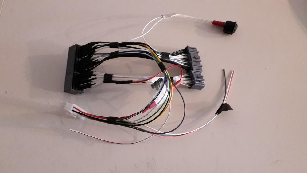
-
It looks like the B7 and B8 pins are now bridged, The IGF wire signal is now being sent to pins B7 and B8 on the ECU (ignition feed back from the B8 wire of the EP91 plug, B7 is empty on the EP91 plug). Essentially you are taking the engine management back a generation. To get rid of the variable TPS on the EP91? You'd need the 50mm fte TB (which you've already said in a previous post on a different thread will hurt drivability on an N/A+t.) The ignition conversion loom you said about earlier. There is also the IACV differences to deal with. The EP91 has the water heated electrically operate valve on the throttle body and afaik the gen 1's were the wax stat on TB and electronic valve separate on the manifold. So for turboing an EP91 4efe you sacrifice low down drivability for an easier to tune ECU with a piggy back? This thread is a bit all over the place now mate, N/A+t, N/A gen 1, piggy backs, rrfpr +FCD. Best to try and stay on topic or what you are trying to get across can easily get lost. I know Gavin on here has got a setup similar to this in his N/A which he's happy with.
-
Claymore's sleeper 4efe+t-t+t build (R.I.P. the Nanza)
Claymore replied to Claymore's topic in EP91 Progress Blogs
Thanks mate, comments like this really mean a lot. -
I've already said my opinion on this style of tuning on the other low boost thread. It seems at best to be a very old fashioned way of making something run at an OK level. Or get it wrong and ....... The modern piggy back is cheap, convenient and effective. It will have better fuelling control than the above method (nothing can be exact with a piggy back but it will be more accurate and easier to calibrate than mechanical tuning methods). It can also retard timing when necessary based on a table, something not addressed in your plan outlined above. If cost is the deciding factor then don't forget even a cheap det 3 also has, boost control facility (so no separate EBC required) and datalogging etc. Personally I don't think the results will justify the effort / risk vs piggy management. If your doing it as a technical exercise then enjoy. Look forward to the results / dyno graphs etc.
-
At the beginning of the thread you said you thought it had an FCD. Glad it doesn't. This is the only reason I keep mentioning it. There were different types of FCD some people say they are a voltage clamp (i.e. no modifications of sensor signal output voltage until a set point and then the voltage is clamped at 4.5v for example). This removes boost cut but puts you in "no mans land", boost increases, no more voltage increase and no safety net. Too much boost, engine go boom. Some FCD's are a signal conditioner constantly, they remove a set amount of voltage throughout the sensor 0-5v range. same as an offset in the det3. So 1v becomes 0.8v 2v becomes 1.8v etc. The voltage modifiers won't stop a sensor going out of range and not reporting boost increase: i.e. 5v flatlined on boost it just clamps it at 4.5v with no increase as boost increases. Or turns it down from flatlined 5v on boost to 4.5v with no increase in voltage as boost increases either. Won't work for 1bar sensor on NA+T but was used back in the day to defeat / delay boost cut on Glanza's running close to limit. And again, none of this is recommended.
-
Claymore's sleeper 4efe+t-t+t build (R.I.P. the Nanza)
Claymore replied to Claymore's topic in EP91 Progress Blogs
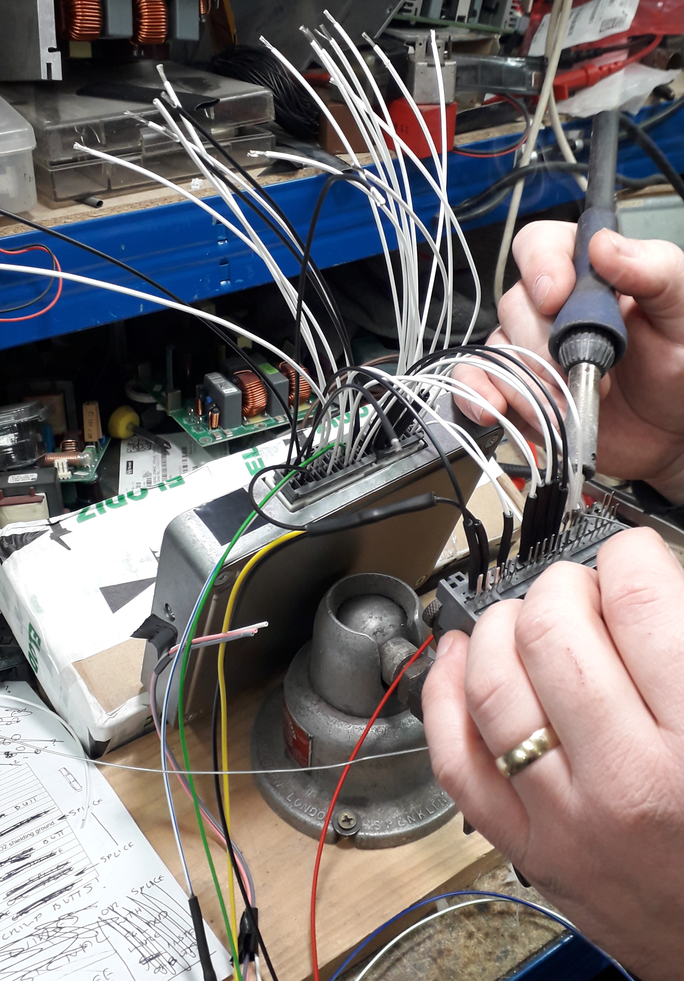
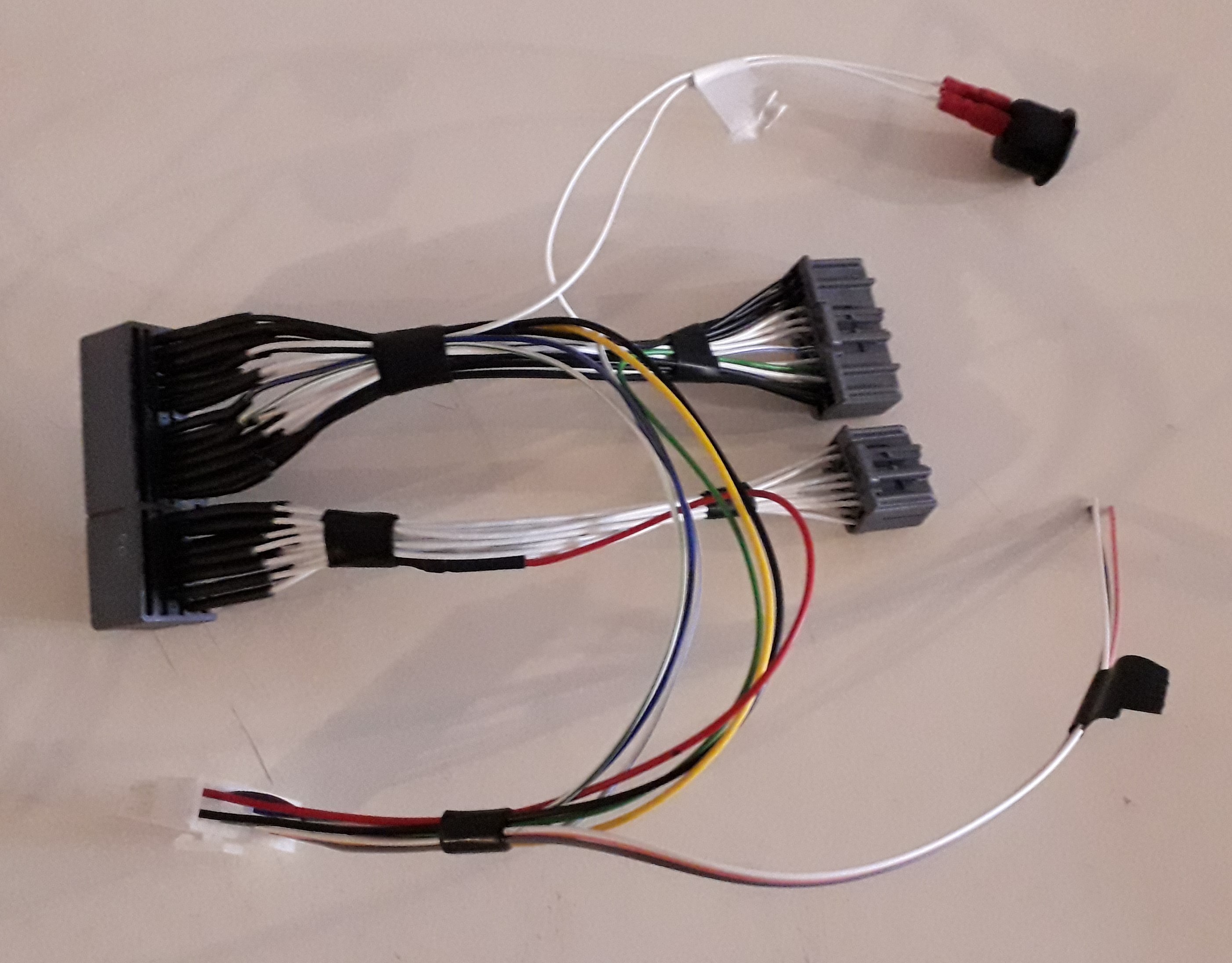
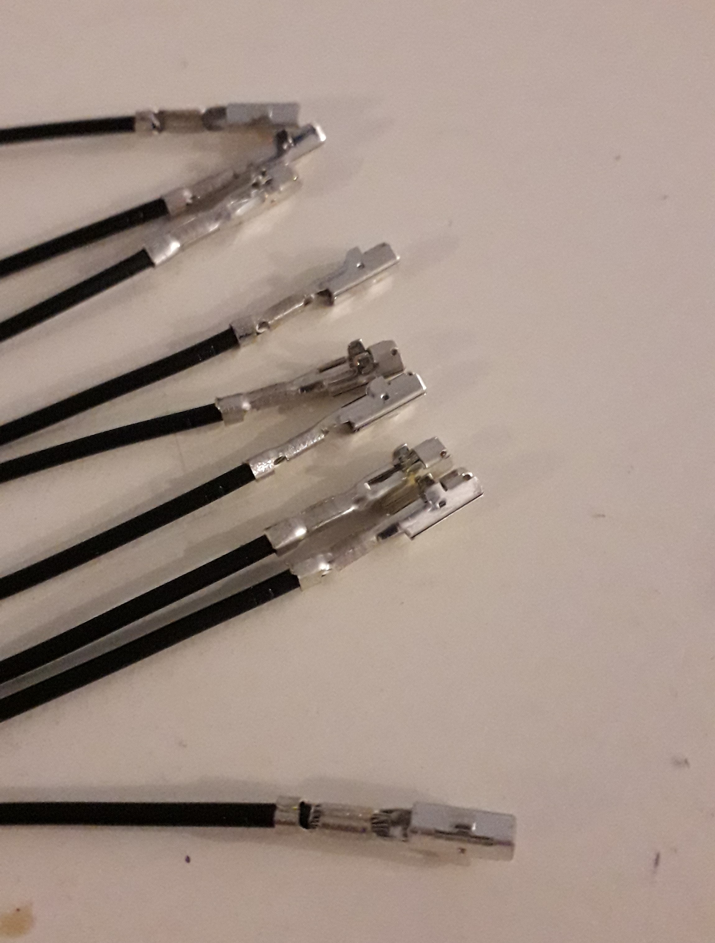
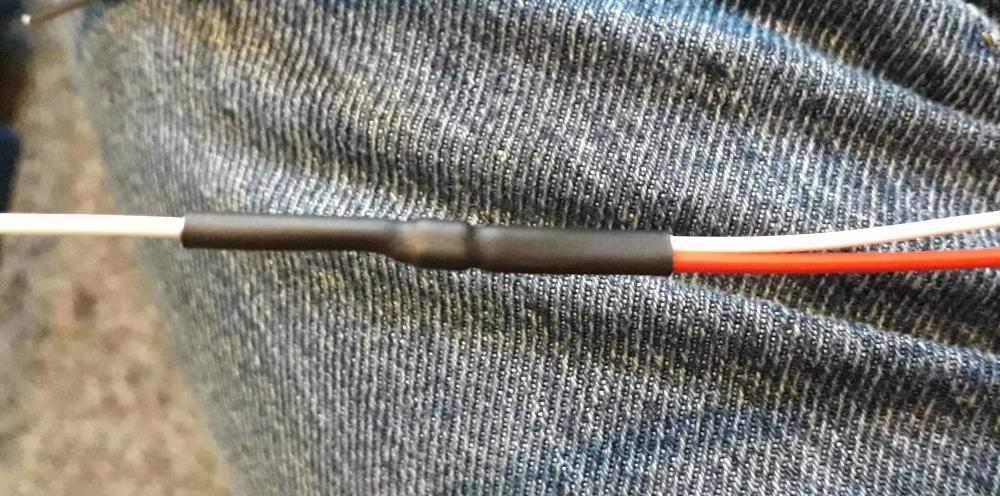
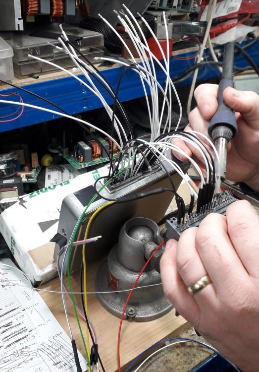
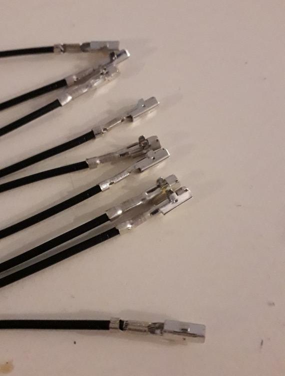
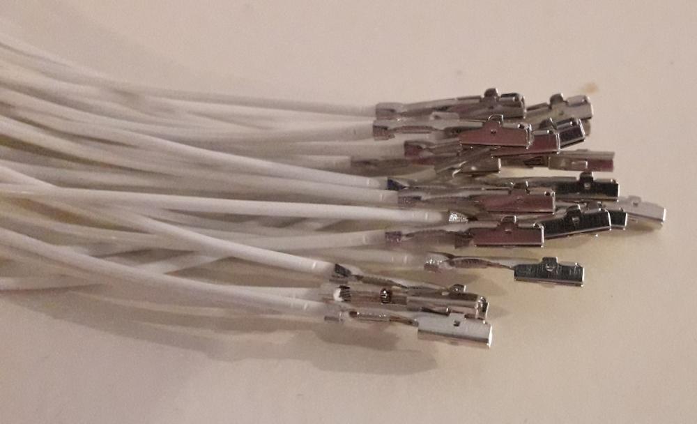
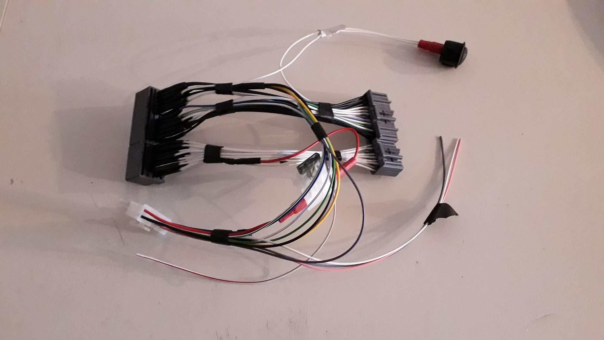
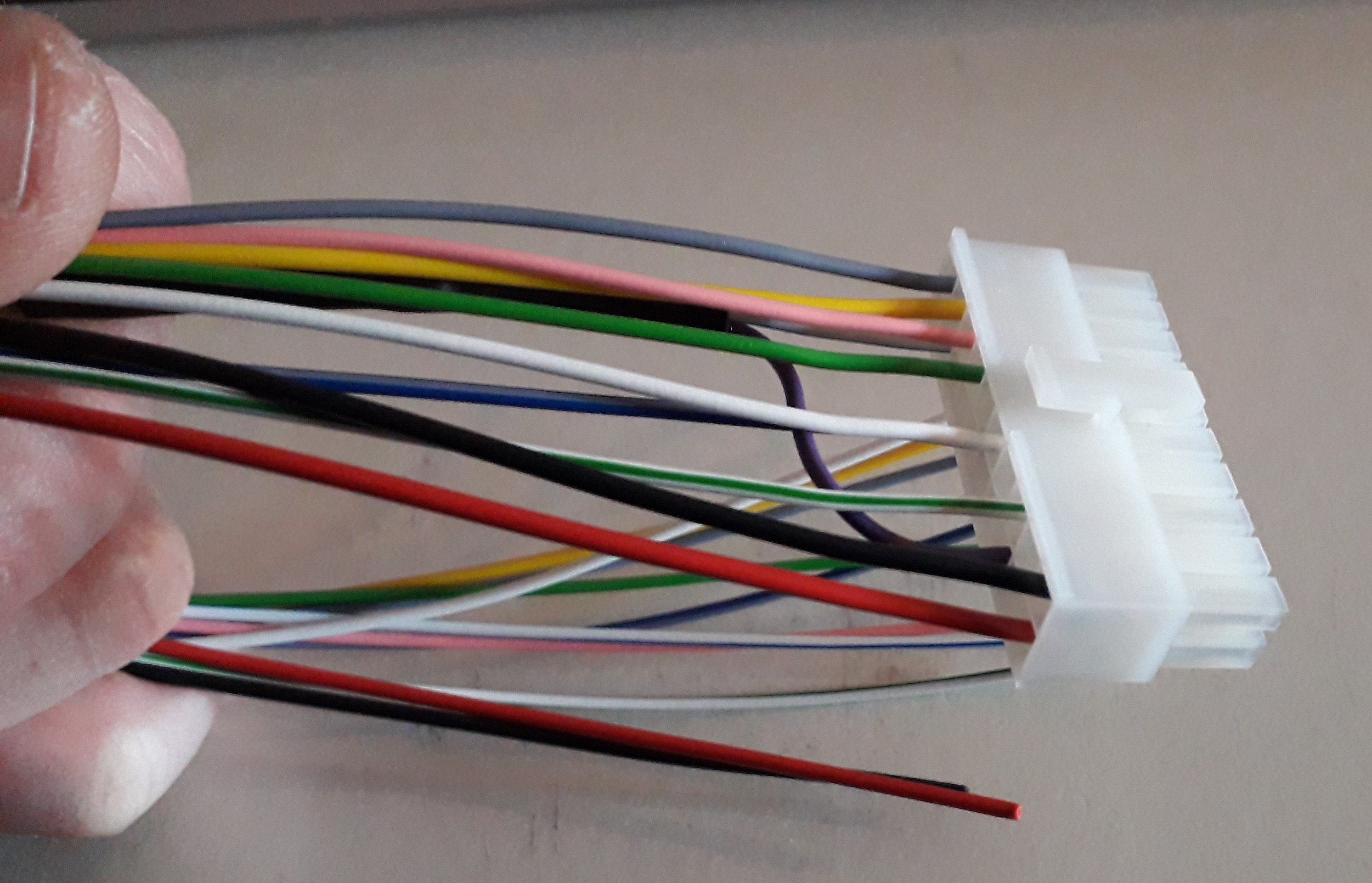
Next I chose the wires I would require and fitted them to the Piggy back ECU plug. I bought the ready made leads with contacts crimped on from ECUmaster to speed up the process. I also loaded the patch wires into the TE plugs, there is a plastic retaining clip to release first, slide wire in (listen for "click" of tab engagement) then close clip. The power and ground needed splicing into the patch wires, so the brass open barrel crimp was loaded into a different pair of "mighty" W crimp pliers. (the light duty ones wouldn't be up to the job) And the part stripped patch harness power wire was crimped to the piggy back power supply. Lots of force required as the pliers were short handled and the splice barrels are very robust. Glue lined heat shrink for added strain relief. Can't solder for shit and didn't fancy learning on this project so I decided to pay my friend (professional electronics engineer) to solder the wires to their corresponding contact. I even got the special old school lead solder as its better than the modern shite. Remember to add heat shrink to wire, prior to soldering. As she stood after soldering. Pleased with the outcome, Tested the harness for continuity and resistance and all was well. If I had to do it over again I would change a couple of things but I'm very pleased with the harness especially as its the first I have made.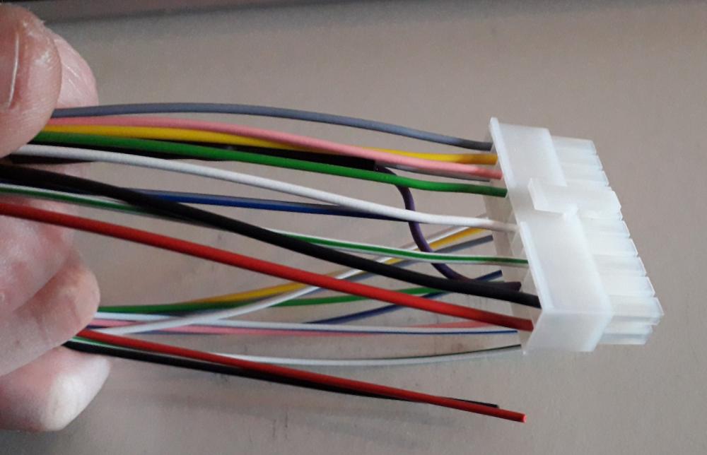
.thumb.jpg.9ca0a17b6c5e297ec4e5de9bf9af1e5d.jpg)
-
Claymore's sleeper 4efe+t-t+t build (R.I.P. the Nanza)
Claymore replied to Claymore's topic in EP91 Progress Blogs
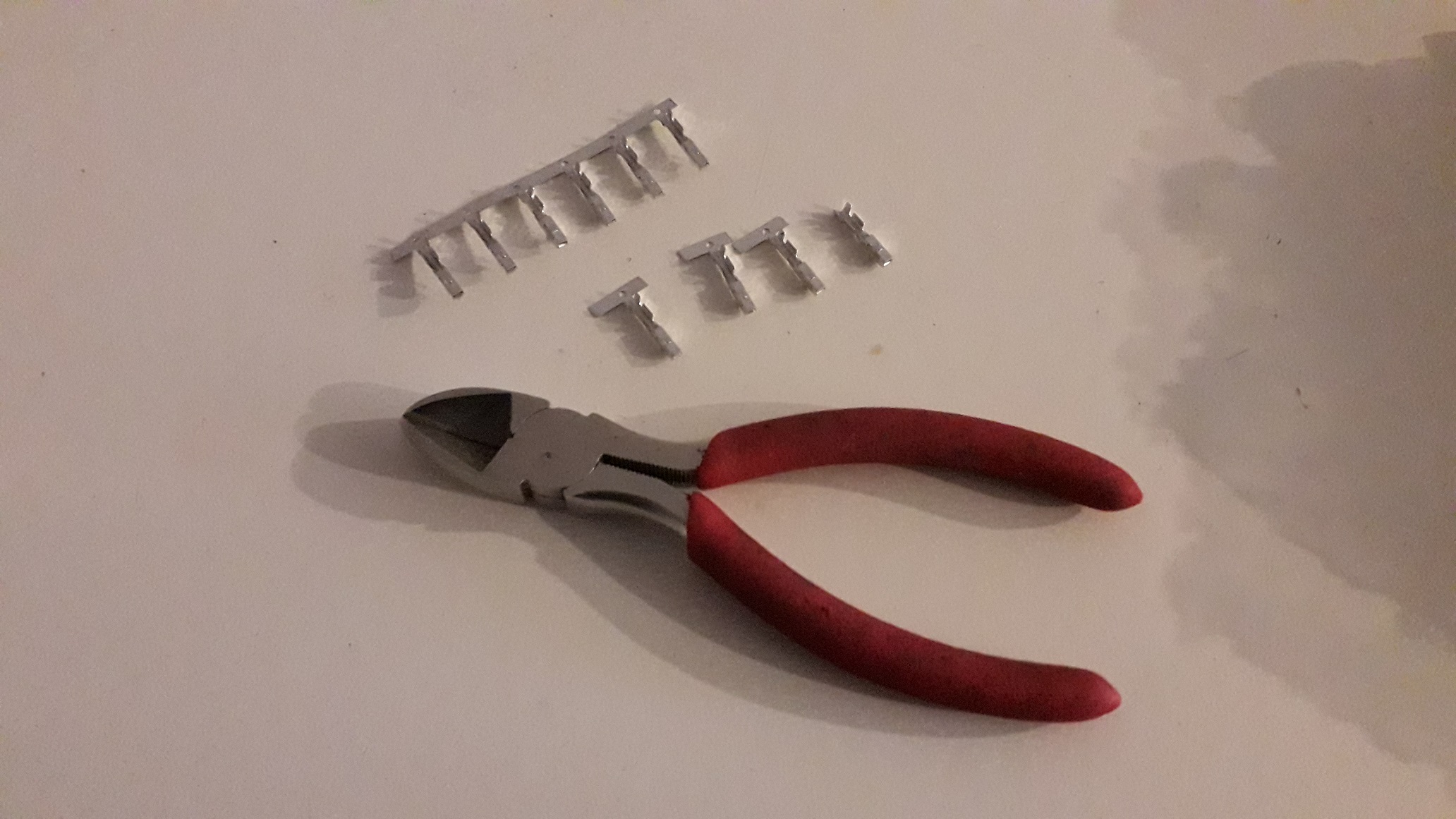
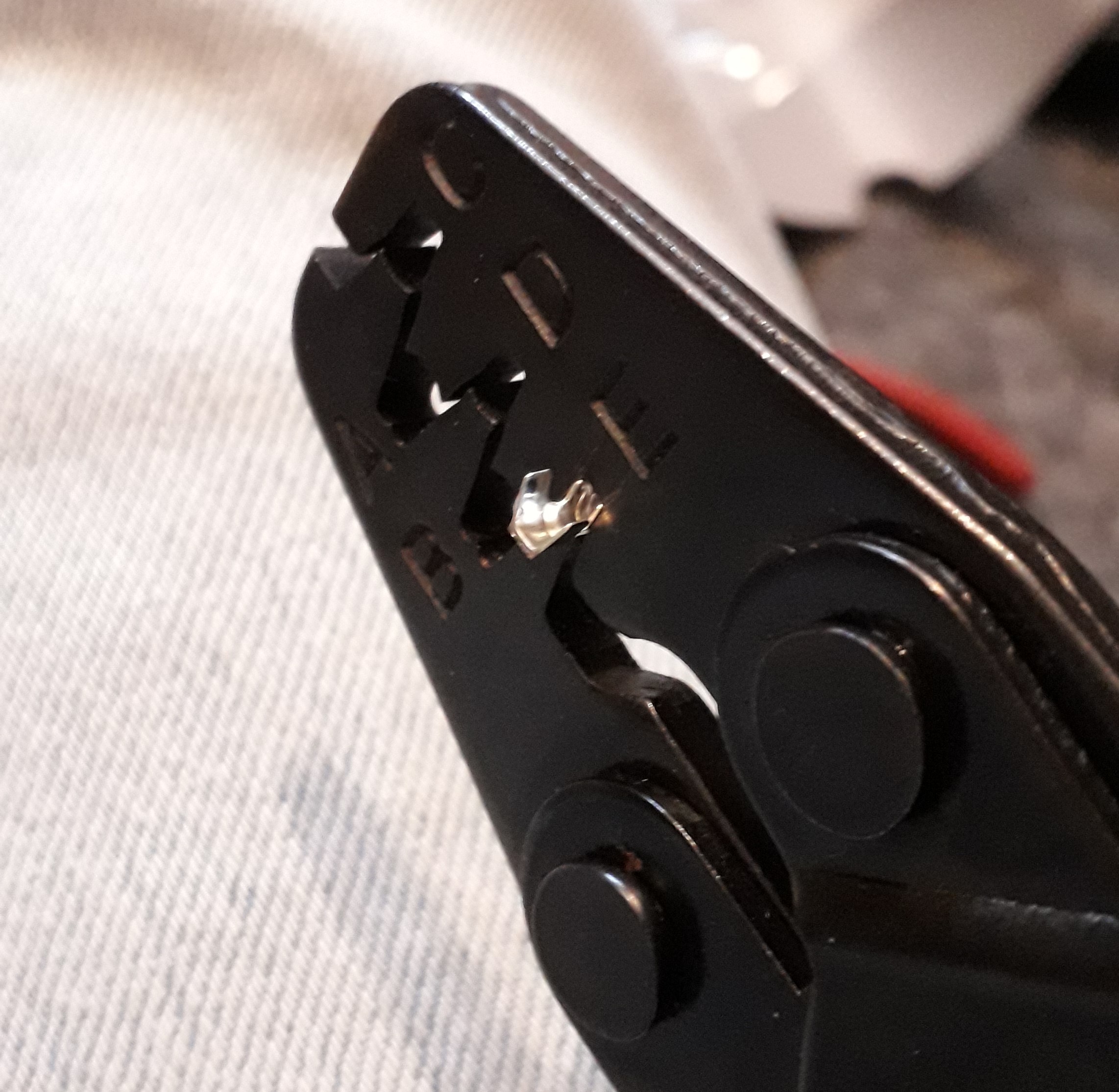
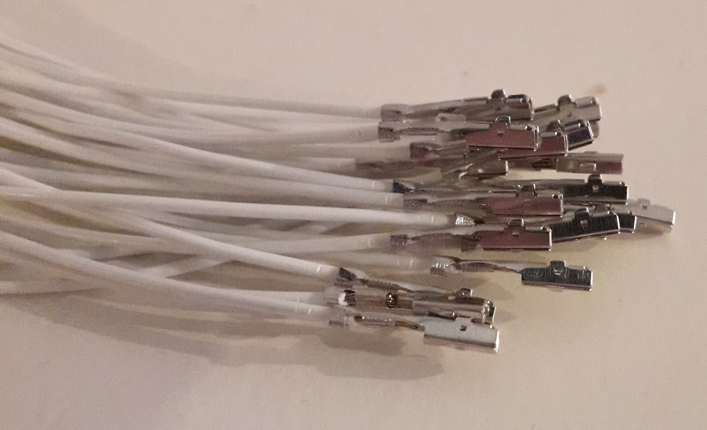
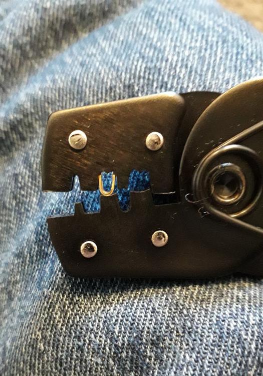
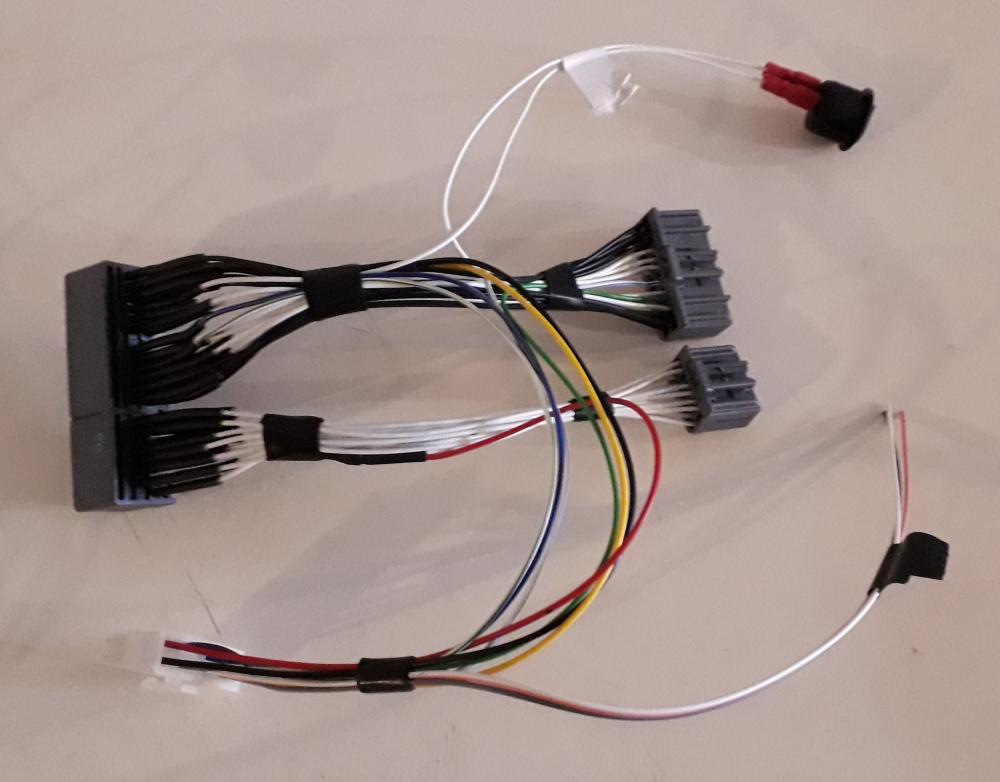
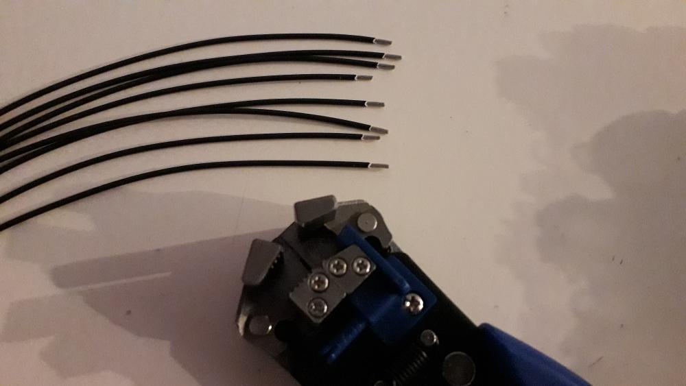
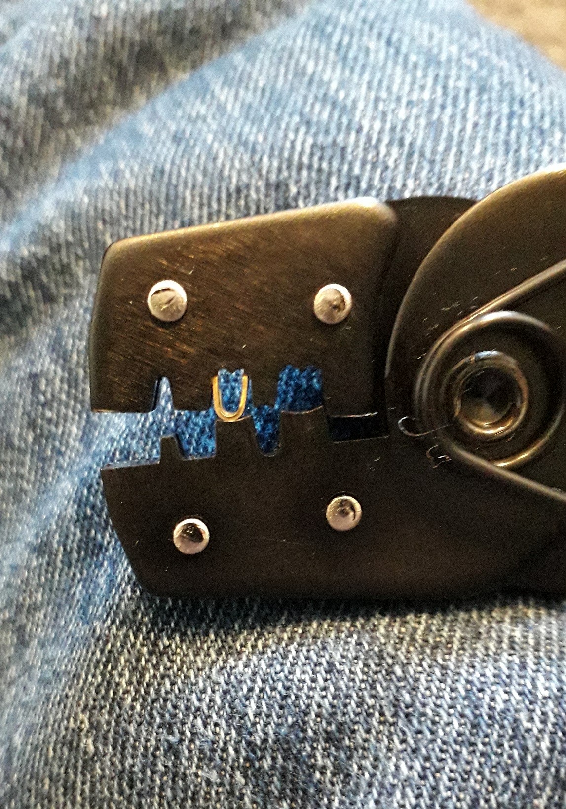
Moving on to the wiring side of things I needed to make up the required number of patch wires to go from plugs to header. If it was a patch harness all the necessary wires would be installed and then you would cut into them (as if it were the car loom) and then plug it in between the car loom and ECU. It quickly turned into a plug n play loom. The only difference is the intercept wires for MAP sensor and ignition wires are attached directly to the plug and header instead of cutting into a patch wire. This removes some of the connections to improve reliability but will make the harness piggy back specific. Large contacts cut from strip (of 100!!!!). Tails cut off next. Wire stripped Using a W form crimp tool I first squeezed the crimp barrel til the sides were vertical. Inserted into the correct sized jaw. Add wire to barrel and crimp. Then crimp strain relief barrel section closed onto the insulation. Large contacts done. Repeat for small contacts. I took the time to practice crimping some spare wires and terminals to make sure I knew which size jaw to use. I also strain tested the connection to make sure I had learned the correct amount of crimping force required. Each wire was visually inspected and "reasonably" strain tested to ensure it was good to use.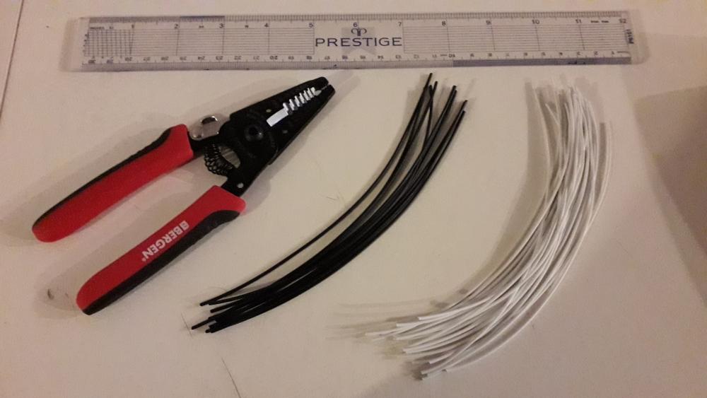


-
Claymore's sleeper 4efe+t-t+t build (R.I.P. the Nanza)
Claymore replied to Claymore's topic in EP91 Progress Blogs
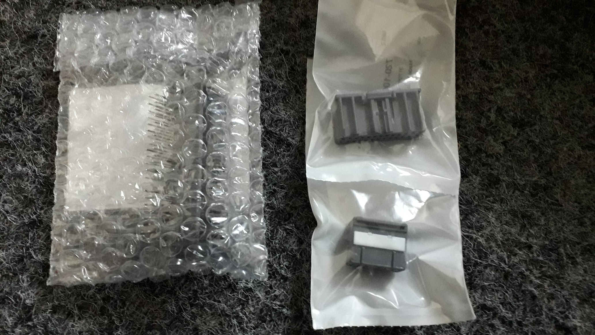
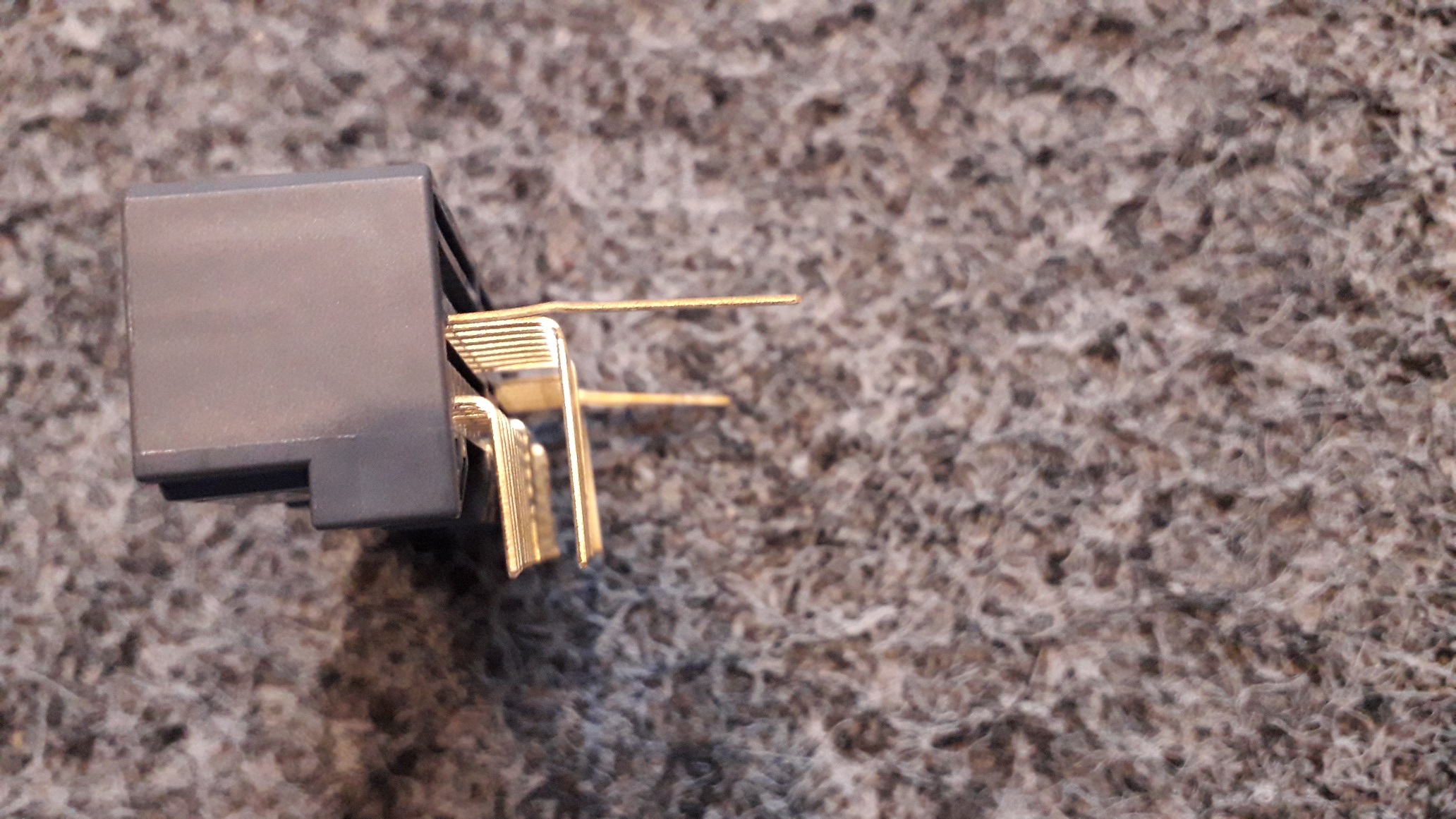
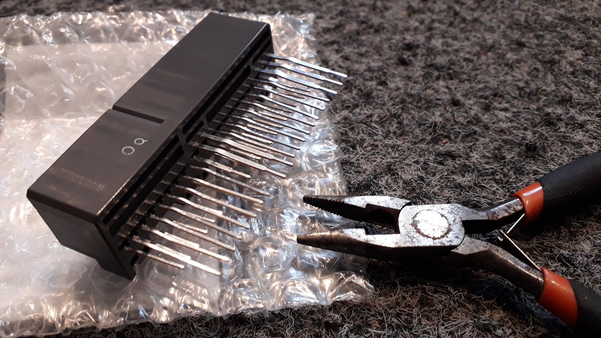
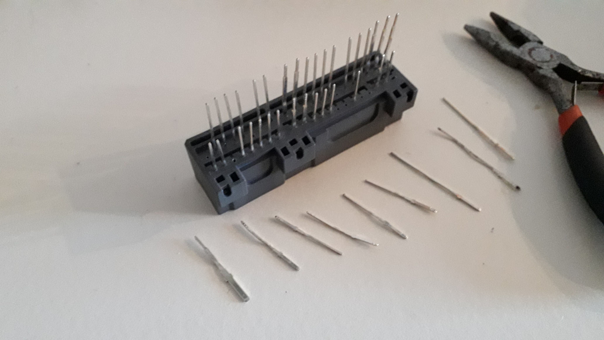
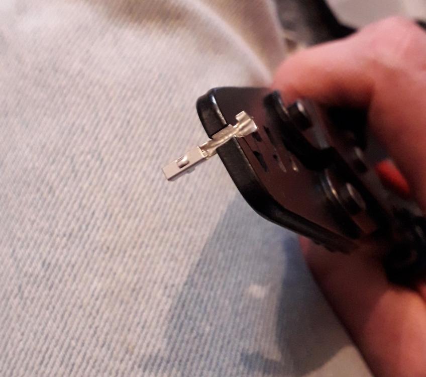
ECUmaster DET3+ plug n play harness. https://www.youtube.com/watch?v=dXtzCMs2b6Q Thought I'd make my own pnp harness for the det3 install to save chopping the car loom. Also makes it easier to work on / add connections to it rather than scrabbling around in the footwell.. First, a big thanks to RoyalDutchie and Rob SR at RaceCal Ltd. for their help and guidance. Purchased the necessary wiring loom plugs and the ECU header (socket). They are TE connectors and have 2 different sized receptacle contacts. These are unfortunately only available to buy by the 100. I needed 10 large and 30 ish small 😡 The ECU header is designed for surface mounting so the contacts are 90 degrees to the socket. Thankfully they were tin coated brass and were easy to straighten out. All straightened (Ignore the state of the pliers please) Not all the contacts are used on the starlet so I removed the unnecessary items by pulling the contact out from the "plug in" side (opposite side to shown). This gives more room when soldering the patch wires on later. However it will prevent the potting of the connector as the liquid epoxy would seep through to the plug side. The pins were trimmed down to approx. 15mm.


-
My main post was regarding the Toyota 1bar sensor and trying to use it on a 4efe+t. In response: If the Toyota Hylux sensor you are using (that says vacuum sensor on it) can see 1 bar atmos and 1 bar boost (2bar sensor) why is there a FCD fitted to the vehicle? If you boost more than 1bar then you will be in "no mans land" as I described above? Seems unnecessary unless it is to add an offset voltage to the signal if the AEM can't do it? Just seems weird. I remember reading in the Jeff Hartman book that some Honda map sensors (used on N/A) can read up to 0.8 bar boost. Looks like this was what you had. The problem maybe that the 0psi voltage (3v? ish) when sent to the honda ecu causes boost cut like when the Toyota 4efe ecu sees 5v?ish. Dunno. The point I was trying to get across is to choose the correct size (2bar, 3bar, 4bar etc) MAP sensor for the intended boost level. With enough room to spare for the cold, dense weather days. Yes I see what you mean with the TPS influencing fuelling in the Toyota ECU as a "correction" to the MAP signal used for load. My previous car had the basic tps switch (idle, nothing and then full throttle). When off idle switch: it used a flap style AFM with NB O2 feedback (closed loop) and on full throttle switch it went open loop and only used speed density (AFM vs rpm). All very 80's technology. Not sure about fuel cut voltage on the 4efe, must be around 4.5v or higher if the Glanza is anything to go by. Should be easy to test with a 1bar sensor plugged in (N/A+T) and the piggy scale set to volts....then change back to a 2bar obviously. Yes, I will have to run a cat for MOT / street legality. 200 cell sports type. I will also be using the O.E. NB lambda as long as it doesn't intrude too much regarding short term / long term fuel trims in (closed loop) that are contrary to the requested fuel trims in the piggy back. (I have actually put a switch into the plug n play harness I made to disable the NB O2 signal to the Toyota ECU if necessary 😉). I will try to record my mpg figures but as this is a weekend toy and not a daily driver it's a low priority for my build. I'll see what she does on cruise for a laugh but I'm not spending hours of time and money to develop that side of the build. With 2 map sets available in the piggy, a lean cruise / low boost table could be built if necessary as an easy / uncomplicated half fix. Press the button again and full boost party mode enabled! Still at the beginning of the build really for me, but looking forward to it more than ever.
-
1 hour ago, Sam44 said: im also going to try and setup the output of the original map sensor to accept boost pressure like i did on the turboed civic d16y8. ----------------------------------------------------------------- The problems as I see them is, when the 1bar sensor reaches 0psi boost (1bar atmos, at sea level, relative humidity etc.) the signal produced is 5v. If it receives 1psi boost or 100 psi boost the voltage stays at 5v. The ECU has a fit at 5v so you can use an offset in the signal (say -1v) so now we hit boost, the signal is a constant 4v. This signal is acceptable to the Toyota ecu but whenever the engine is on boost there is no increase in voltage to differentiate between 1psi or 100psi. So you will have to add or subtract the necessary voltage to the constant 4v signal to increase or decrease the fuelling from the Toyota ECU. This may be ok if the det 3 has enough scope to get the fuelling right, if not the 4v + 0.5v you add won't fuel enough for example. The other issue is if you use this signal for load also (the signal that moves you around the fuelling and ignition tables in the piggy back) when you are on boost the cursor will just go up and down on the 5v line of the table corresponding to the revs, no influence from boost pressure so if you have 1psi (5v) at 2000rpm or 100psi (still 5v) at 2000rpm you will be in the same cell. Obviously this would require seriously different fuelling. You could use an inbuilt 4bar map det 3 and use its inbuilt map sensor for load. This would move you around the map with a 4v signal to modify. Let us know how you get on. You mentioned that your current setup has a vac sensor and FCD and piggyback. It's not that different from the setup above. The vac sensor is voltage offset / clamped by the FCD (otherwise what's the point in fitting it?), sent to the piggyback where it is most likely moved around the table by the inbuilt map sensor of the AEM whilst the piggy adds or subtracts the necessary voltage to the signal to fuel it. Just a thought I had over xmas when you mentioned it. Might not be the setup at all but its the only logical reason to use the components he did!? Just to add, if this is right, its a bad idea and I don't recommend it. I'm just thinking out loud.
-
I did think about the 1bar MAP sensor thing, not sure it can work if used for load. I'll put a post on the below thread to try and keep this one on topic.
-
Good shout on the IAT sensor for logging. I only have the Analogue input #4 left empty so could splice into it for the signal.
-
Yes, have got a timing gun. Might as well link these vids here (try and get some sort of database): https://www.youtube.com/watch?v=_z5hnVmlyuI
-
https://www.youtube.com/watch?v=psa4l2wEOYs Setup I'm using for det3+, IGT (currently, may go VR) and Glanza 2 bar MAP fuel table modify= analog in #1 (Glanza 2 bar MAP sensor) load = analog in #1 (Glanza 2 bar MAP sensor) correction #1 = disable correction #2 = disable ignition load = analog in #1 (Glanza 2 bar MAP sensor) correction #1 = disable correction #2 = disable scale configuration analogue #1 = vw 200kp (2bar map. same scale as glanza sensor (I think) changes the table scale to bar instead of 0-5v. Need to compare to actual boost gauge to check they match) analogue #2 = Det3_with_400kpa_MAP (This is the inbuilt map sensor that is hard wired to analogue 2 on the board. Don't try to use analogue input 2 as it doesn't work! None of this is mentioned in the manual. Had to call customer services to find out which input the inbuilt MAP was on and how to choose this as a datalogging / load / modify signal) analogue#3 = AEM AFR (I will have the wideband O2 sensor signal connected here for datalogging, might be able to use it as a correction on the fuel / ignition table also !??) analogue#4 = 0-5v scale (IAT sensor signal input for data logging. Currently using generic voltage scale until I can work out the calibration volts vs deg C. Might be able to use it as a correction on the fuel / ignition table also !??) ignition configuration Ignition mode: Retard a single signal (for IGT. Not sure for VR) Ignition input type: Hall effect or optical (for IGT. This will change if going VR.) maximum rpm 6500 (I've read that 6200 is redline for the 4efe, managed to rev mine to 6200 last night hence the 6500 limit for tables) number of signals per 720 = 4 maximum retard = 50deg (maximum possible in the det3 afaik. Need to be careful how much you use as it may end up firing down another plug lead.) Leaving the analogue input / output configurations for the minute but these will be "sized" as appropriate for the sensor range the engine actually uses when its up and running with turbo. Don't need to clamp the output so probably leave as is. Hope this helps. Some of this is from the budget starlet turbo build video on youtube so thanks to that guy for helping already also!
-
Currently (IGT, no pullup) the car runs, has rpm signal (700rpm at hot idle) has ignition state as synchronized and moves the cursor around the map when throttle is applied. I haven't yet tried to adjust anything in the ignition table. Might be best to attach a timing light, pull out 10 deg at idle and see if the timing marks go from 10 btdc to 0 deg on pulley. At least I'll know if the timing is actually moving! Also, if I were to go the VR wiring route, does it matter which wire is used? NE or NE-? I'm fine with mechanicals but this is my first foray into engine management. Couldn't find any info on a google search about what others had done, there must be plenty of users out there so hopefully people will want to share. (PM if you want to)
-
Stupid double post
-
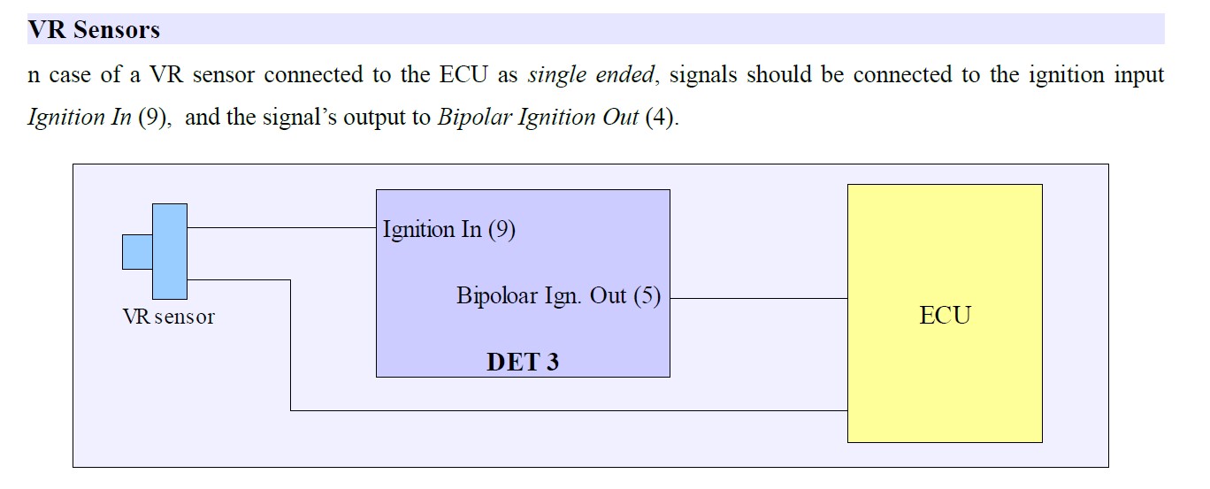
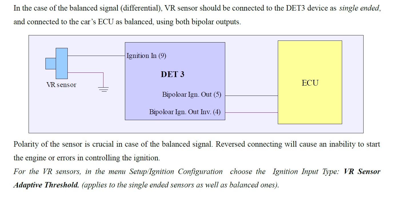
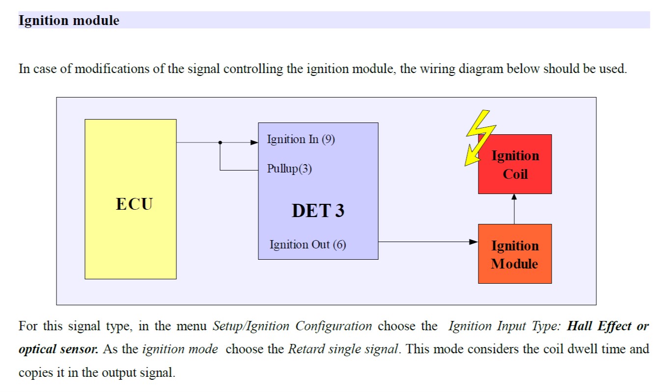
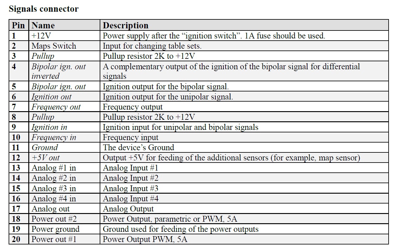
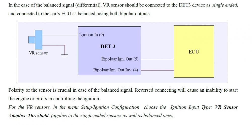
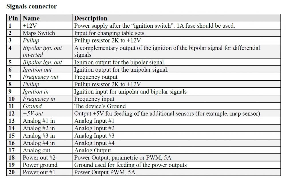
Currently the NE and NE- aren't involved. Not tapped into and not intercepted. The Det 3 only has one ignition input and so you have to choose. I used the IGT signal as it seemed to fit with the diagrams relating to ignition module controlled by Toyota ECU found in the 4efe and the advice in this post: I also checked other piggy back wiring instructions (EMU) and it always said intercept the IGT and PIM to modify (4efte), splice into the other wires for reference values!?!? The analogue inputs are for 0-5v sensors i.e MAP, iat, tps etc. I am modifying the Toyota MAP signal which will be the glanza 2 bar sensor for fuelling changes. I am using the Toyota map signal as the load signal vs rpm also on the fuelling table. Current wiring = pin1 : switched +12v (spliced to Toyota ECU switched wire) pin3 : Pullup spliced to 9 (currently depinned as won't run if connected to det 3 plug) pin6 : Modified IGT signal to ignition module (intercept) pin9 : IGT signal from Toyota ECU (intercept) pin 11 : ground (splice to Toyota ECU ground) pin13 : MAP sensor signal wire into det3 (intercept) pin14 : No wire connected (Internal MAP sensor of DET 3 is hard wired on board) pin15 : Wideband O2 signal input. pin16 : IAT signal (spliced to Toyota sensor signal wire) pin17 : Modified MAP sensor signal wire to Toyota ECU (intercept) pin18 : Shift light (wired to LED) pin19: Additional earth required when using power outputs pin18 and 20 (spliced with pin11 to Toyota ECU ground) pin20: Boost control solenoid (wired to boost solenoid) I do have other unterminated wires in place for other analogues, boost control and shift light etc. but these are not the concern currently. The wire options are: IGT (ignition timing to ignition module), IGF (Ignition feedback - not of any use), NE and NE-. The wiring diagrams for VR are: There is also optical / hall diagrams or SAW EDIS.

-
I've installed the det 3 in the Starlet today (97 model EP91 4efe) and made a plug n play harness also. I followed the diagram below (splicing the no3 pullup wire [2k to12v] into the no9 ignition wire) found in the instruction manual. Configured the setup menu's but the car wouldn't start. I checked everything twice before and after install, returned everything back to stock and it ran. Re-installed the piggyback and harness. The software client said Ignition status: no synch. So I depinned the no3 wire from the piggyback plug and the car fired up instantly on the next try and ran well. So to make sure the diagram didn't mean add a 2k resistor from pin 3 to pin 9's wire I tried that and the car wouldn't start again. My question is: how has everyone else wired in their det 3 for ignition. With pullup connection or without? Currently I have the cut ignition wire (IGT) into the piggyback on 9 and out on 6? If I follow the instruction manual with the pullup connected the car won't run.

-
Claymore's sleeper 4efe+t-t+t build (R.I.P. the Nanza)
Claymore replied to Claymore's topic in EP91 Progress Blogs
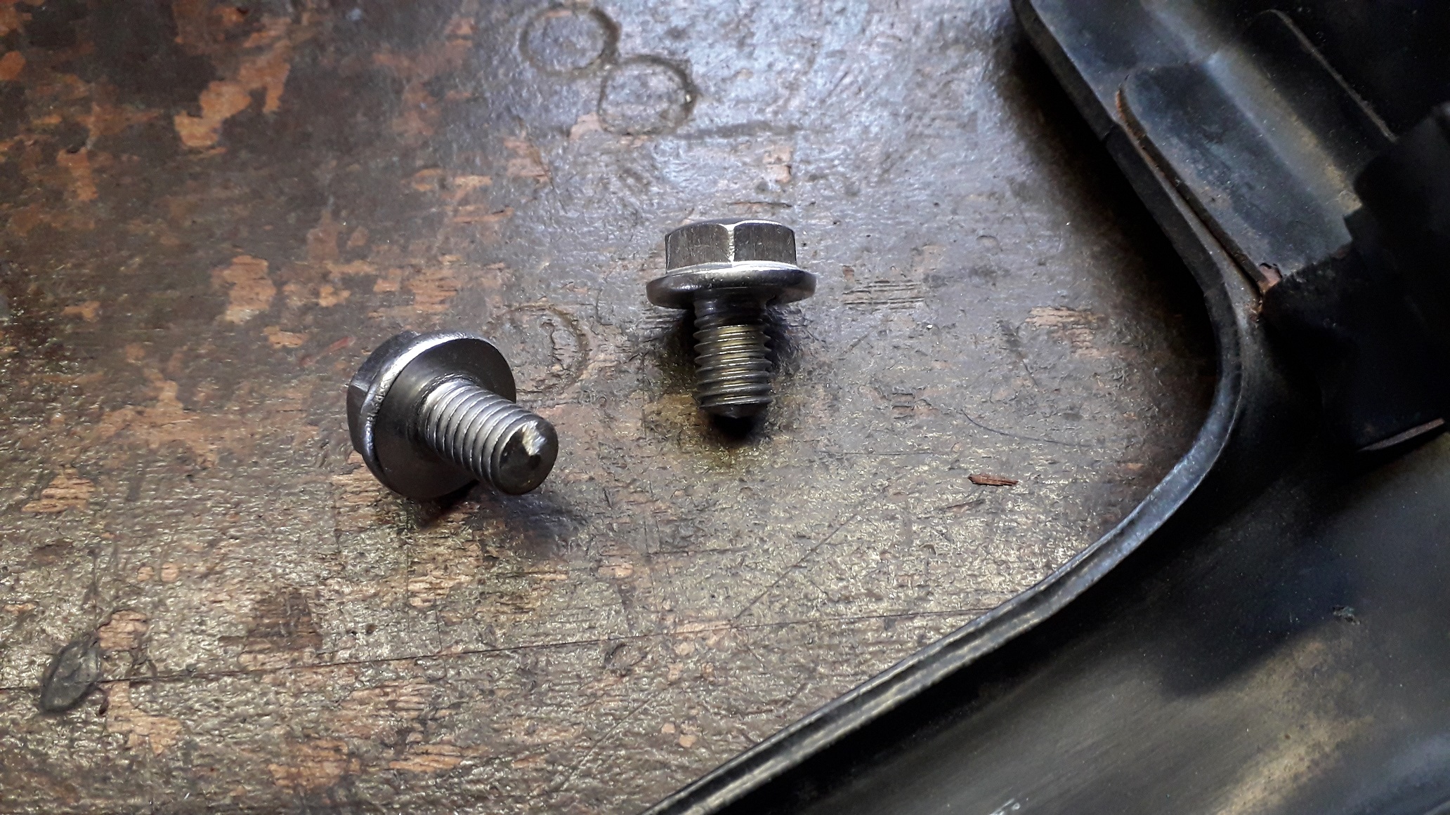
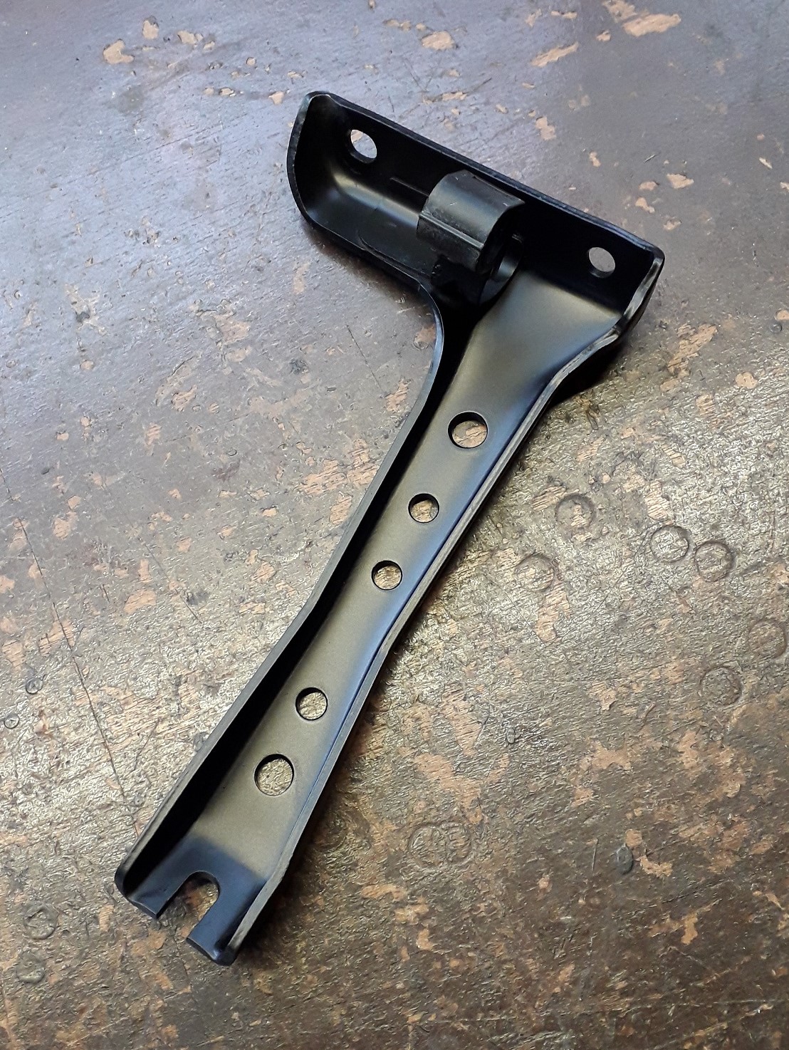
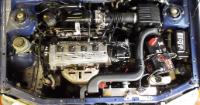
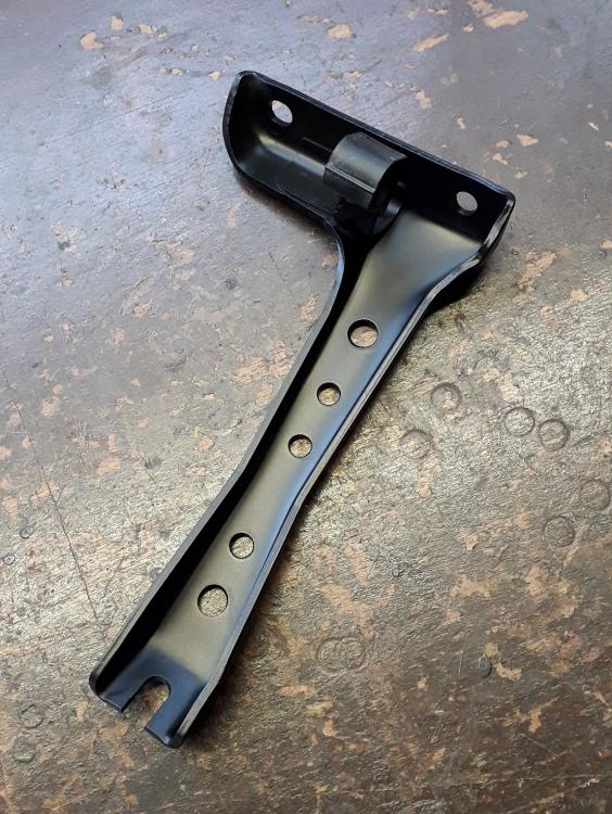
4efte manifold lower bracket. Bought some m 8 x 20 flange head stainless bolts and shortened them to the required m 8 x 12 ish. The bracket is of very generous gauge steel so I also drilled it for lightness and painted satin black. Thankfully the manifold is now ready for install. 💪😃. Still need to mod the throttle cable / bracket but it'll be easier once the manifold is in with the throttle body attached.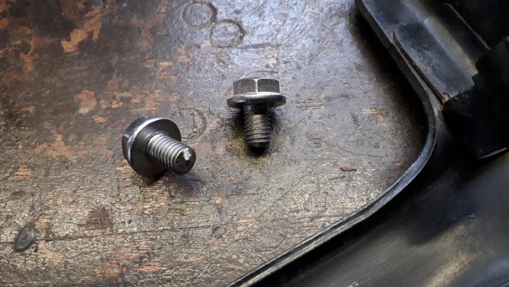
-
Claymore's sleeper 4efe+t-t+t build (R.I.P. the Nanza)
Claymore replied to Claymore's topic in EP91 Progress Blogs
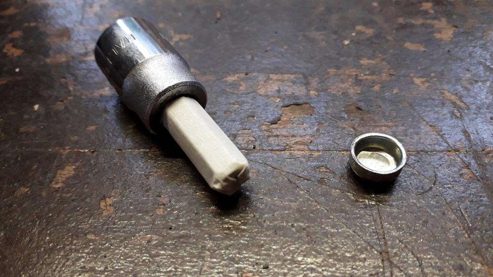
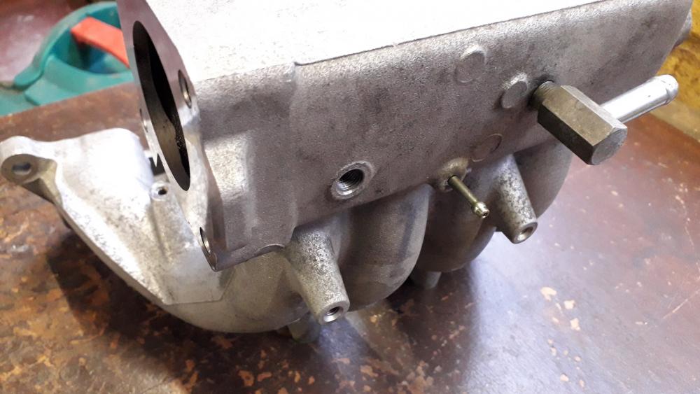
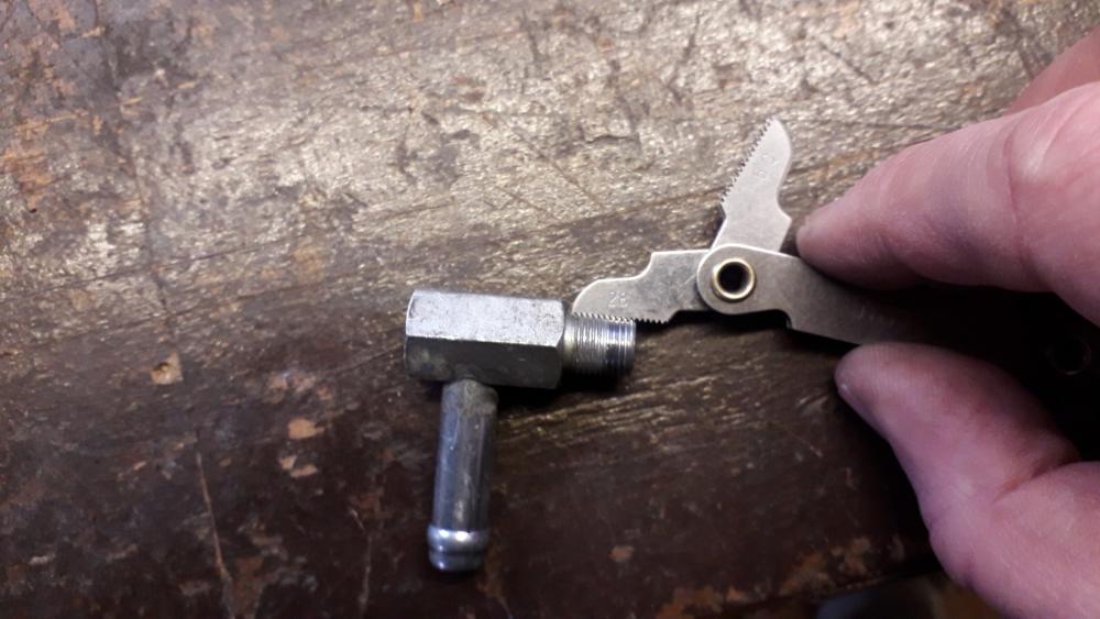
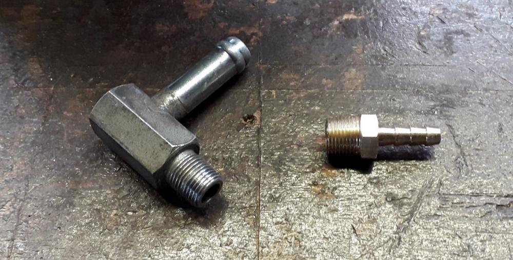
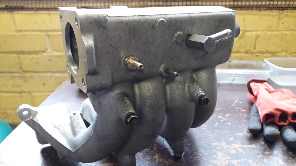
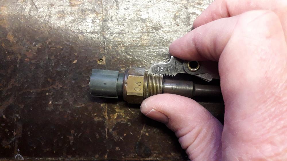
4efte inlet manifold modification. So, with the plate made to fit the fe throttle body to the fte manifold I made some mods to the stock manifold to suit the build better. I won't be needing the IACV hole in the end of the plenum (could be used for a MAP sensor in the future however) So decided to block it off. It's an 11mm diameter hole. Bought an 11mm cup type mild steel core plug. It's an interference fit so needs to be hammered / pressed into place. I softened an appropriate size hex bit socket with masking tape and placed the cap on the end. With the outer surface coated in medium threadlock (just in case it needed help sealing) I hammered it in with a 2kg club hammer. Set in place half way along the hole. Would have preferred a brass version to match the Toyota plug above, but they didn't do one in 11mm. Alternative IACV Blanking plate: https://www.youtube.com/watch?v=tn2yOjUDhZA On the rear of the plenum there are 3 fittings (brake servo, map sensor reference and A/C [I think]) the A/C fitting is 9mm and pretty useless so rather than just block it off I decided to replace it with a barbed hose tail fitting that would suit the piggyback ecu internal map sensor fitting. Removed the old fitting and measured it up. The thread pitch is 28 TPI (turns per inch) and the thread ranges from 9.2 - 9.5mm. The thread pitch and diameter relates to an 1/8" BSPT (British standard pipe taper) thread. So I chose a 3/16" (5mm) barb with a 1/8" BSPT threaded end. Fitting arrived and was promptly shortened by one barb to match the length of the other fittings I applied a small amount of medium threadlock to help seal the root of the threads and screwed the fitting in hand tight. Taper threads in this application don't require a lot of tightening, I have always found anywhere from half, to one full turn will seal perfectly well for low air pressure stuff. Half a turn sufficed and the fitting is in. Now can be used as a dedicated source rather than blanking off and tee-ing into somewhere else. I will be using the fe IAT sensor, so the fte one located in the front of the manifold is also redundant. Upon removal and after measuring it is a m16 x 1.5mm thread. Thankfully this is a common size for drain plugs so.... Drain plug installed with copper crush washer. I installed it to 25Nm as a best guess based on other similar applications recommended figure. Neatens it up and also removes the sensor probe from the inside of the manifold gaining plenum volume as a bonus (approx 1.6cc lol🤣)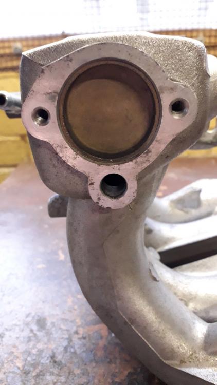


-
I personally prefer a new post for the progress as it happens. That way it's a free bump as well. If I can't remember what happened historically I can always go back and read the older posts. It's your blog mate but I prefer it represented in "real time" if you get what I mean?! A story to follow rather than a refence guide to "refer to page 7 for the gearbox". I rarely go back through older pages of blogs, so unless you've told us you've updated most of us will miss out. Awesome work whatever you decide.
-
I think there are plenty of cheap piggybacks available (like the ecumaster det 3) esp. if you find one second hand. One big problem with not using a piggy back and just "fudging the fuelling" on the n/a is that you won't be able to adjust the timing correctly and the fuelling would probably be wrong somewhere in the rev range. Not worth the risk.
.jpg.acc532ccdf209adc6cf9a108e8a93029.jpg)