Claymore
-
Posts
660 -
Joined
-
Last visited
Content Type
Profiles
Forums
Wiki
Media Demo
Events
Everything posted by Claymore
-
LED's look great and the voltage readout on the charger has to be the easiest way to get a volt gauge installed! Don't forget that editing old posts doesn't move the thread up the list so we don't know you've been updating 😉 Looking more modern every time
-
Good stuff. Welcome back
-
Claymore's sleeper 4efe+t-t+t build (R.I.P. the Nanza)
Claymore replied to Claymore's topic in EP91 Progress Blogs
Thanks mate, Saw your bracket and its nearly there, just needs the humps tapping in to it and a bit of reinforcement at the fold at the bottom. You've done the hard work. Congrats on getting the gt driving, she's looking like a great project. -
Claymore's sleeper 4efe+t-t+t build (R.I.P. the Nanza)
Claymore replied to Claymore's topic in EP91 Progress Blogs
Thanks mate -
Claymore's sleeper 4efe+t-t+t build (R.I.P. the Nanza)
Claymore replied to Claymore's topic in EP91 Progress Blogs
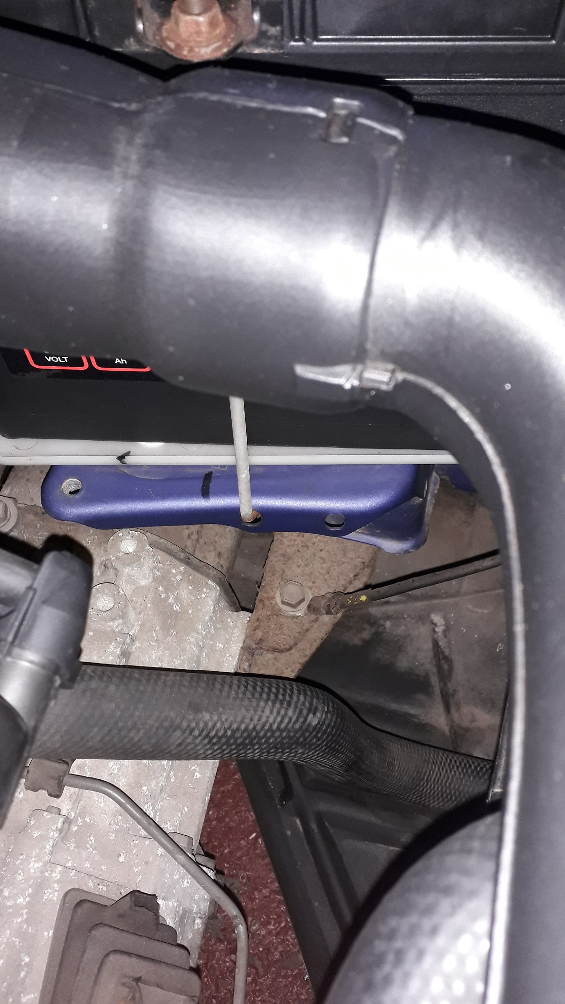
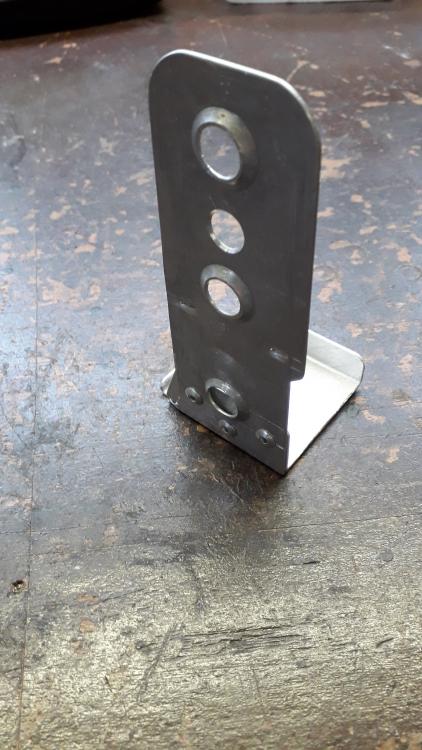
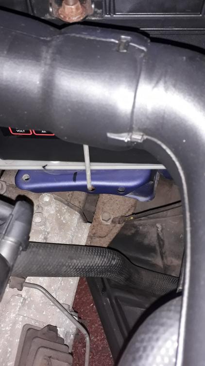
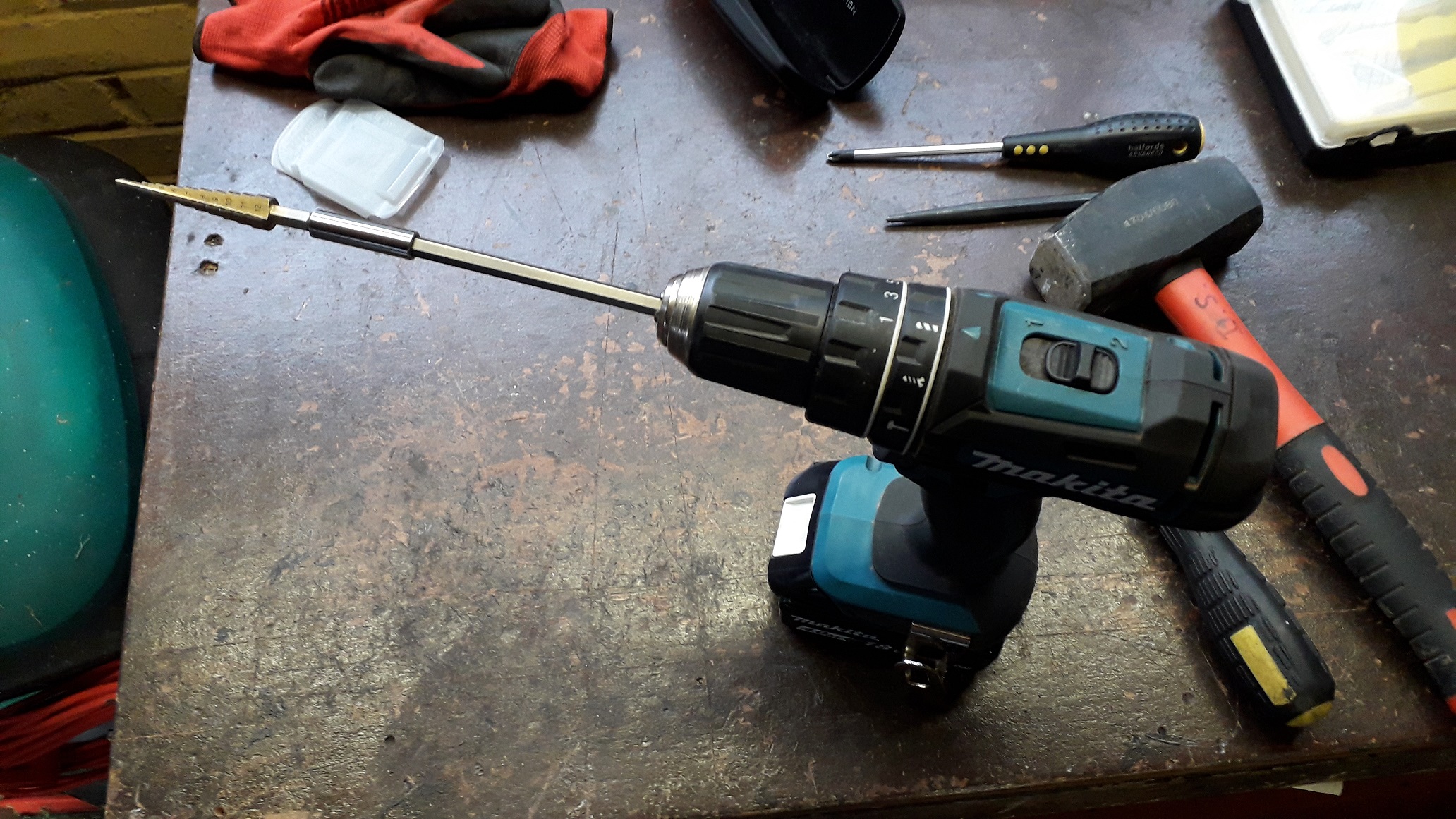
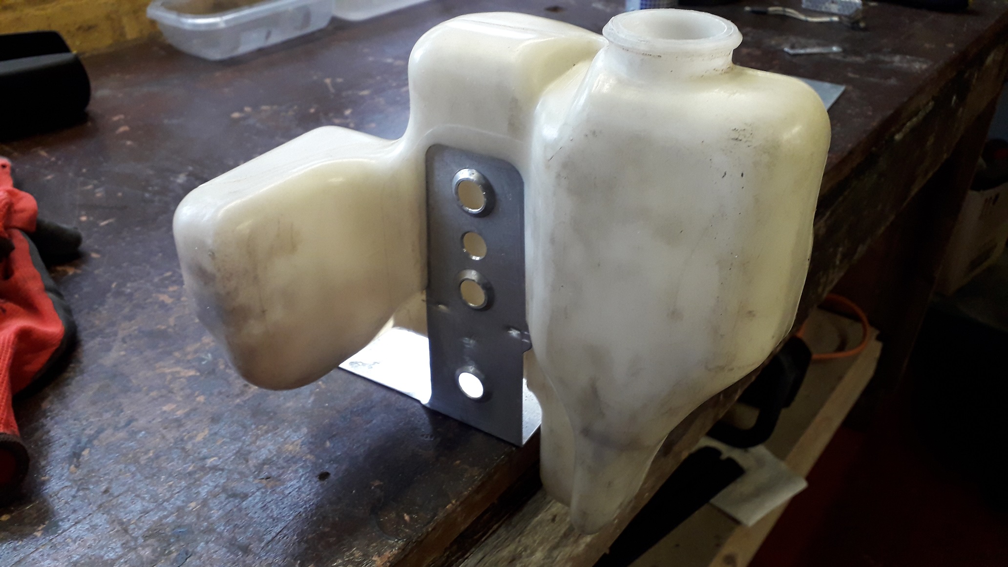
Fitting to engine bay. Needed to drill the mounting holes to attach the bracket. So constructed this contraption to add a bit of necessary peril to the proceedings . The holes need to be very close up behind the headlamp so the body of the drill was too large to locate with a regular bit. The bonus of using a step drill is it only penetrates the metal by the depth of the step rather than getting pulled in all the way like a regular bit does. 2 very wobbly hole drillings later...... Fastened down with sheet metal screws, clipped bottle on. Fits well, the mounting holes are oversize to allow any alignment issues to be corrected for.

-
Claymore's sleeper 4efe+t-t+t build (R.I.P. the Nanza)
Claymore replied to Claymore's topic in EP91 Progress Blogs
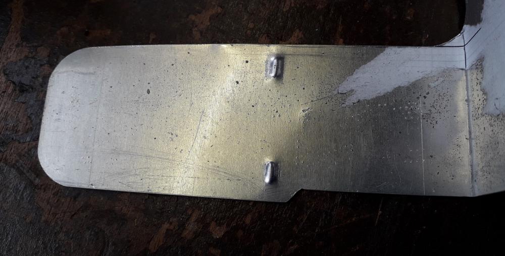
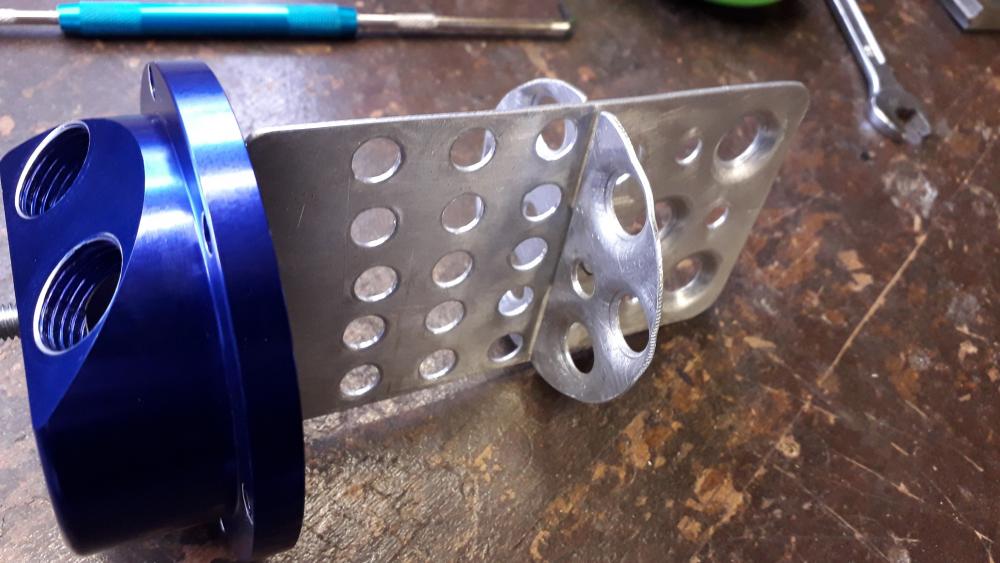
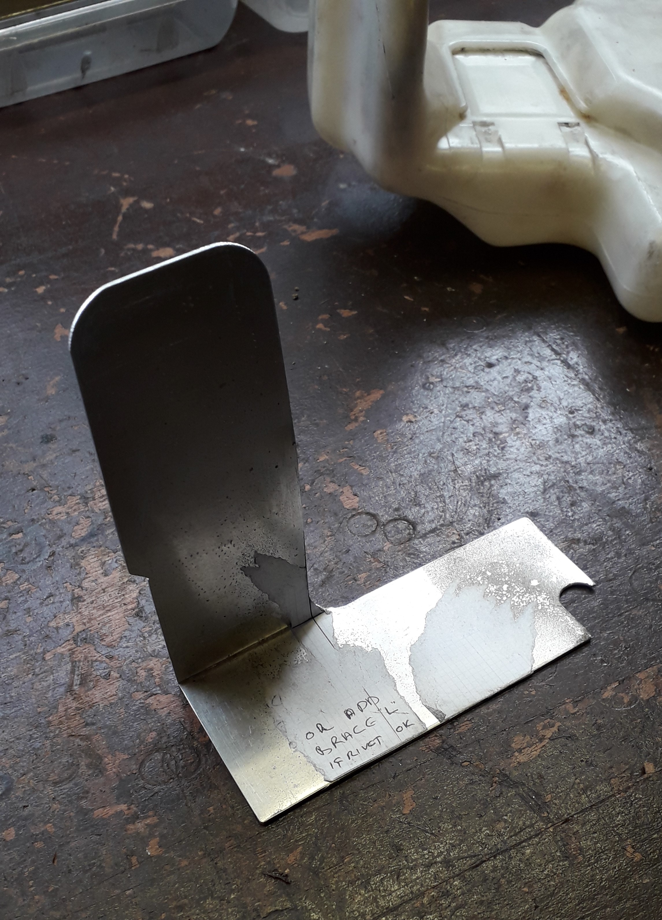
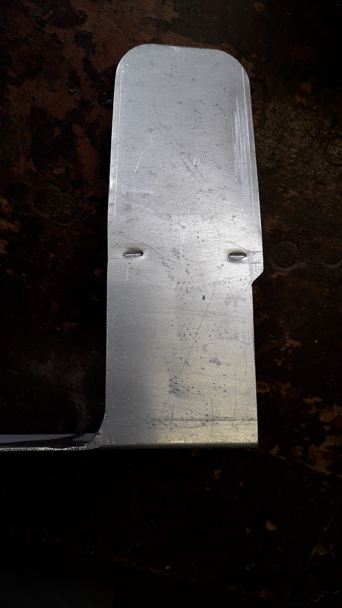
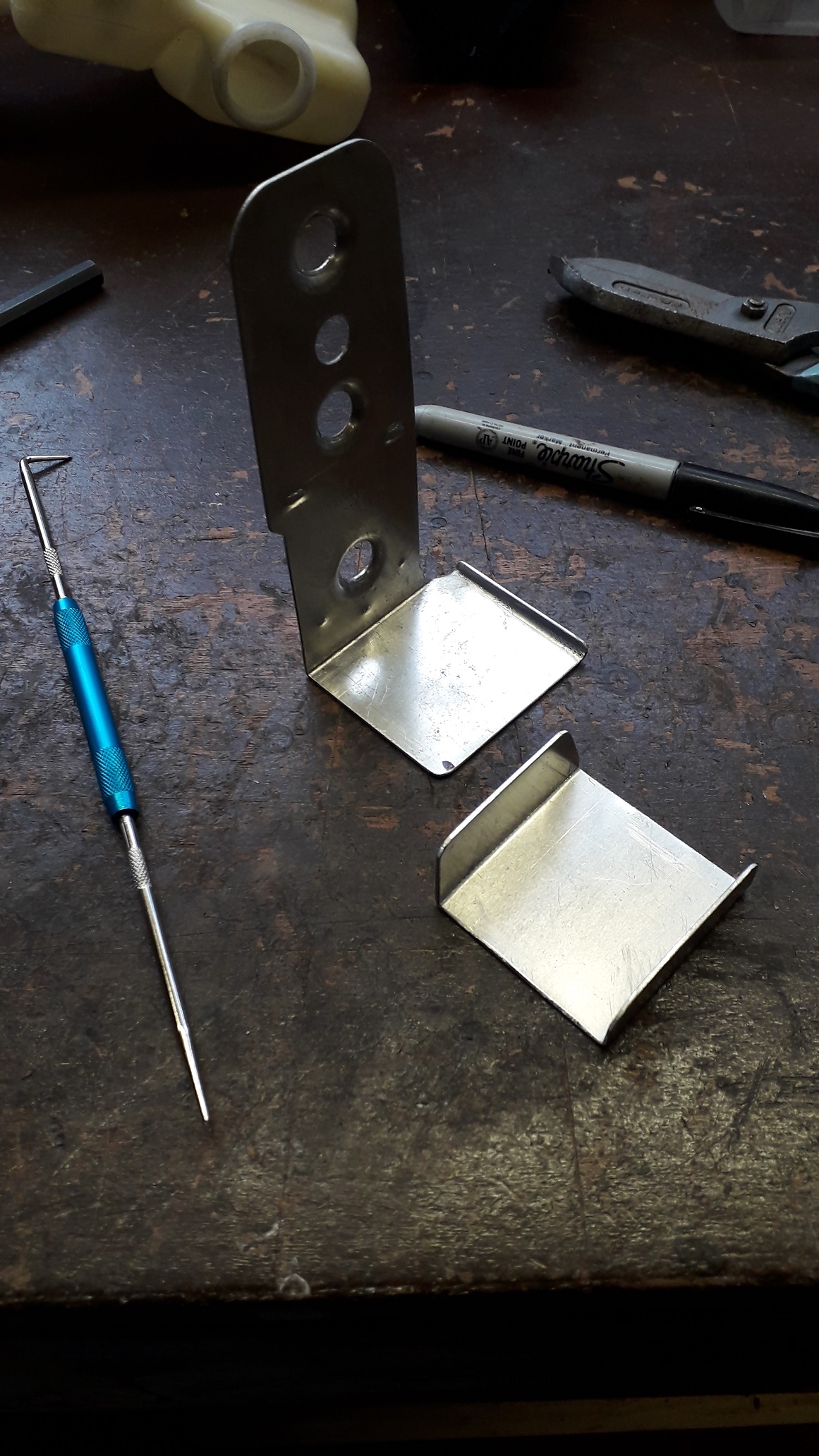
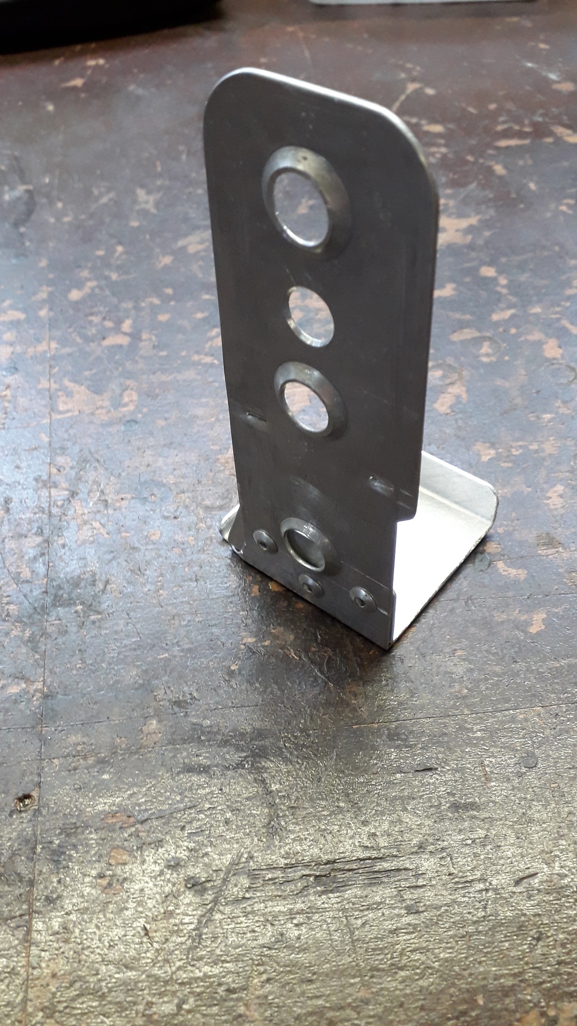
Time to make the bracket. Started with a piece of scrap alu that was already folded to an L shape. Correct thickness to fit into the pocket on the back of the bottle. Tin snipped, linished and filed to shape. The bottle has 2 rectangular pockets moulded into it to clip onto the bracket. Using a trusty old blunt screwdriver I formed two humps in the plate for this purpose. First on a soft surface and made them deeper by opening the jaws of the vice and tapping the features deeper in the vice gap. Drilled holes for lightness and swaged them for strength. Test fitted to bottle with a nice "snap". After test fitting to the car I cut down the oversized foot section and folded the end 90 degrees to add strength. Then made a U shaped section to be rivet on to add even more strength to the fold of the bracket. Drilled and riveted into place. Painted with acid etch primer (because bare metal / aluminium) and satin black top coat.


.thumb.jpg.4787f8dc5e8ea09da3b5e71e978a9253.jpg)
-
Claymore's sleeper 4efe+t-t+t build (R.I.P. the Nanza)
Claymore replied to Claymore's topic in EP91 Progress Blogs
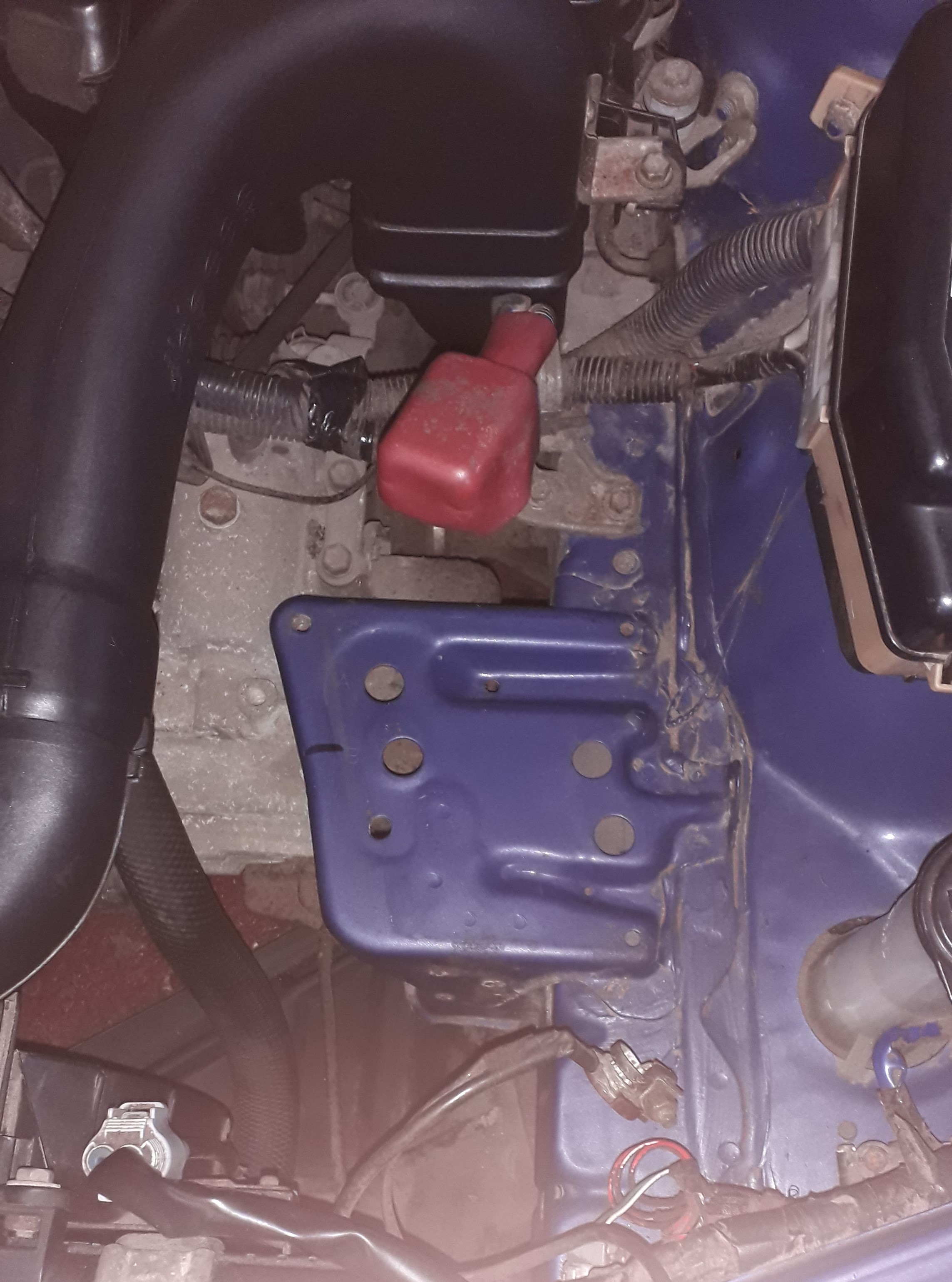
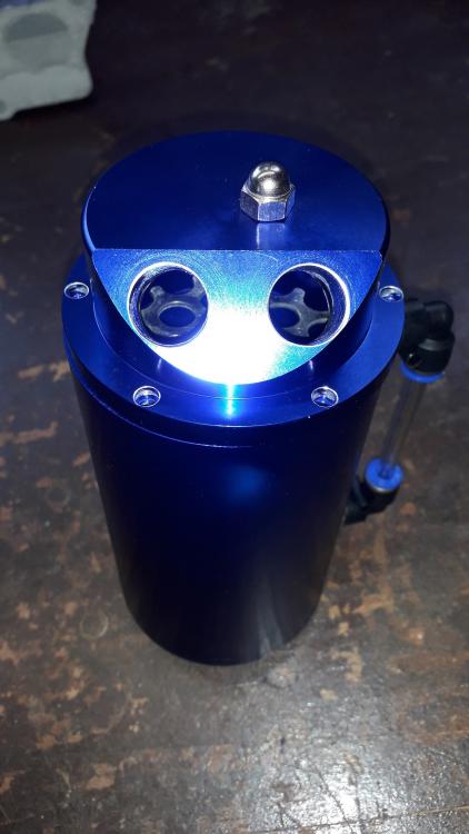
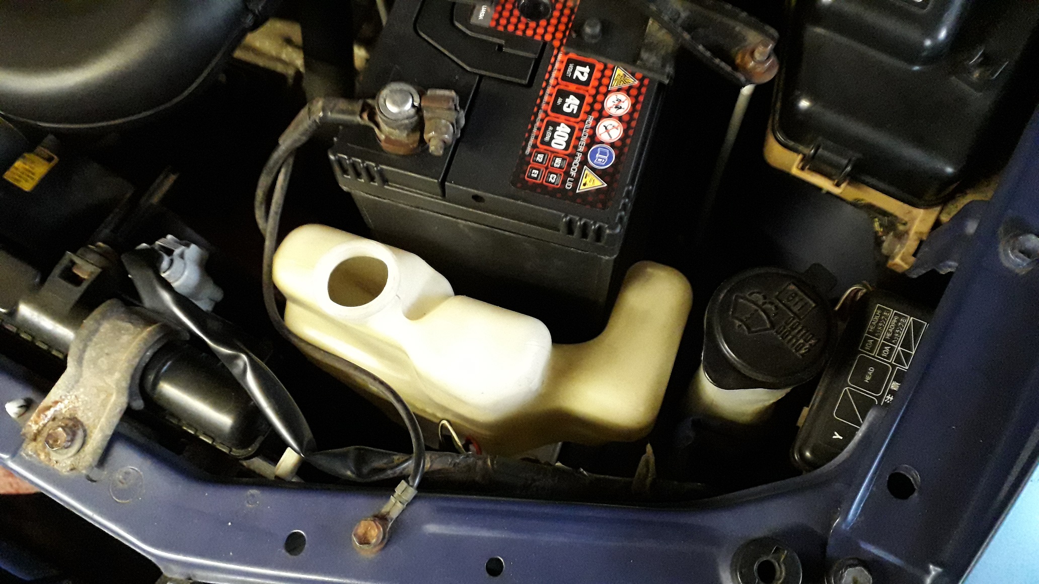
Glanza coolant overflow bottle bracket. Need to relocate the current overflow bottle to the passenger side of the engine bay to free up room for air filters etc. So bought a glanza overflow bottle (they never seem to be advertised with the bracket!) which locates there. First job was to move the battery back, the starlet tray has 2 positions available (A / B ) the posts on the underside of the plastic tray locate in the holes. When using the rear position the drivers side hook has to locate in the rear location to clamp at the correct angle.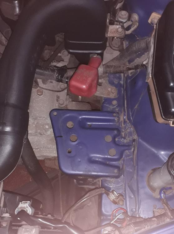
-
I'm trying to figure out the smallest size intercooler I can get away with for my sleeper build. I've got a copy of Corky bell's book and Jeff Hartmans book. Using their method of calculating gives similar results (the hartman book has 2 different equations however which yield different results!?). They also don't specify the length the tubes need to be without some serious thermodynamic calculations to work out the heat removal which needs alot of parameters I can't get without a laboratory. I've done a fair amount of googling which comes up with several different methods of calculating the core size. Some use lb/min some use CFM calculations (CFM for the N/A as boost doesn't affect cfm only air density!?) etc. Then using the CFM calculated on the Bell intercoolers website to check what core size has the required CFM to get rough sizes. I am now at the point where the "required" core size differs greatly depending on the method used to calculate it. If anyone has a sure fire preferred method please feel free to post it up. Or it could well be "pick one that fits in the hole". Cheers (off for a lie down)
-
Claymore's sleeper 4efe+t-t+t build (R.I.P. the Nanza)
Claymore replied to Claymore's topic in EP91 Progress Blogs
That's the plan. Seemed to match the smaller turbo / quicker spool characteristics of the ct9 with short runner exhaust manifold. Prefer to rev a petrol engine for power rather than low down torque and breathless top end (great for a daily though). -
Claymore's sleeper 4efe+t-t+t build (R.I.P. the Nanza)
Claymore replied to Claymore's topic in EP91 Progress Blogs
Thanks mate. -
Claymore's sleeper 4efe+t-t+t build (R.I.P. the Nanza)
Claymore replied to Claymore's topic in EP91 Progress Blogs
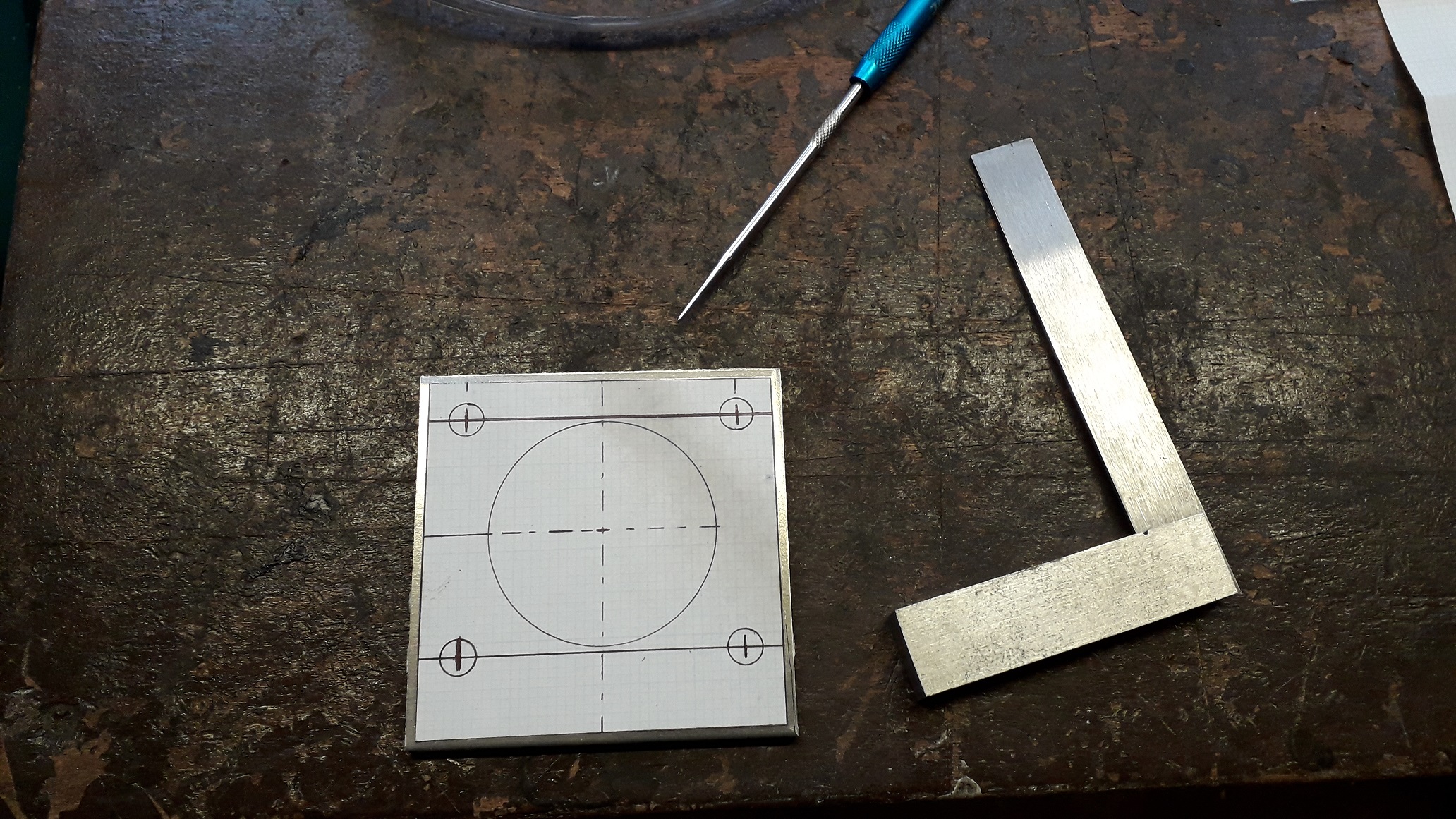
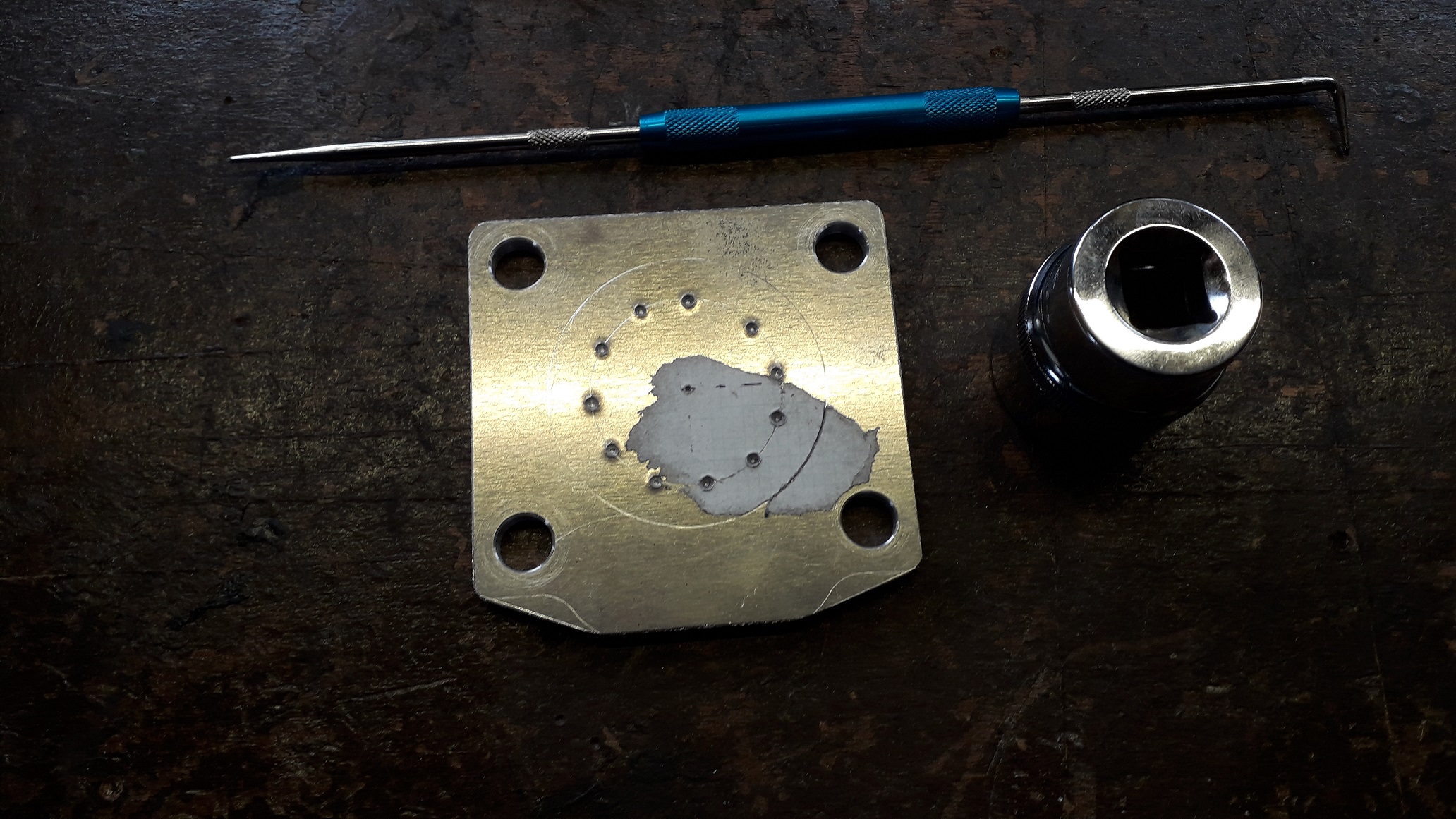
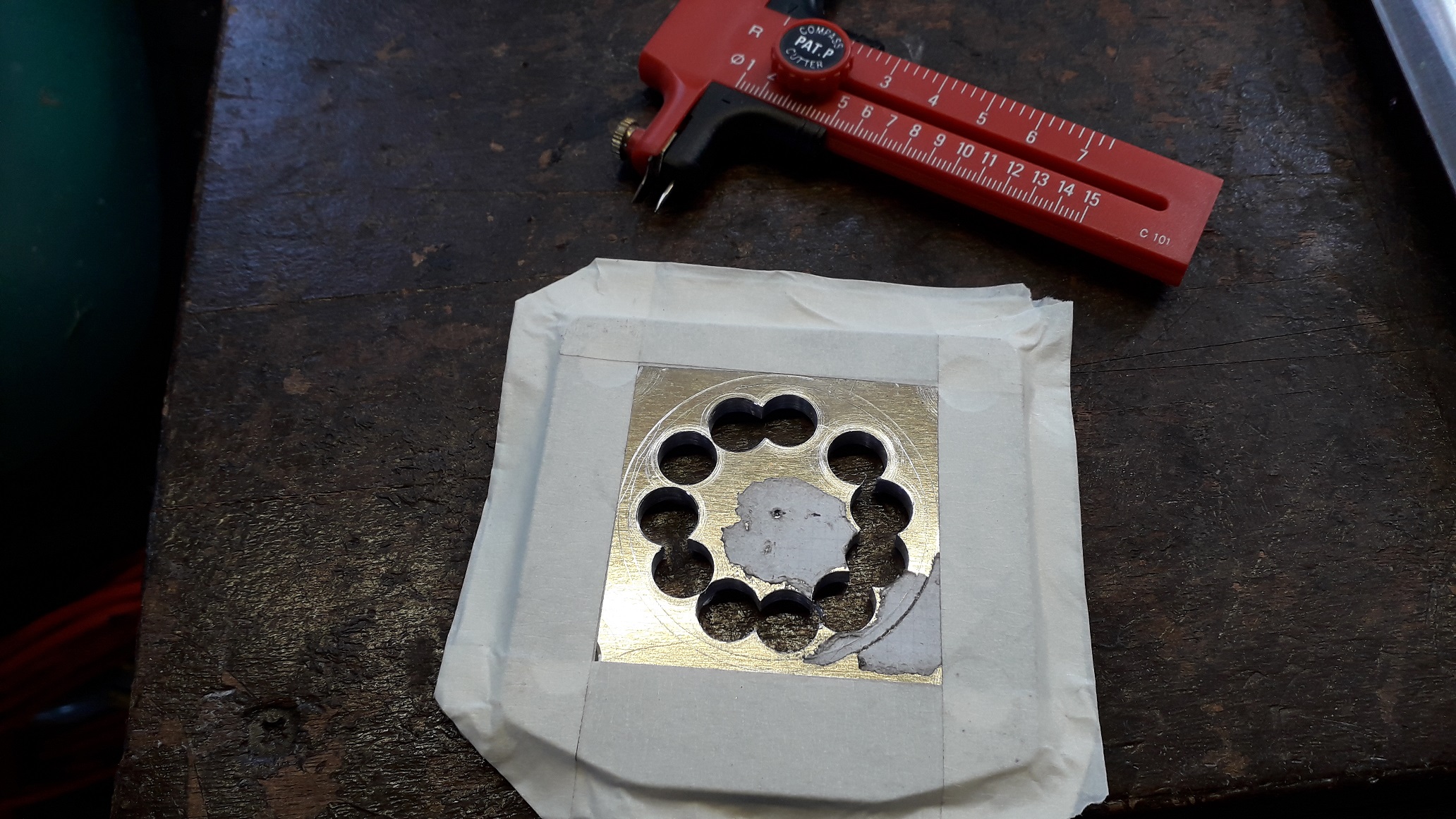
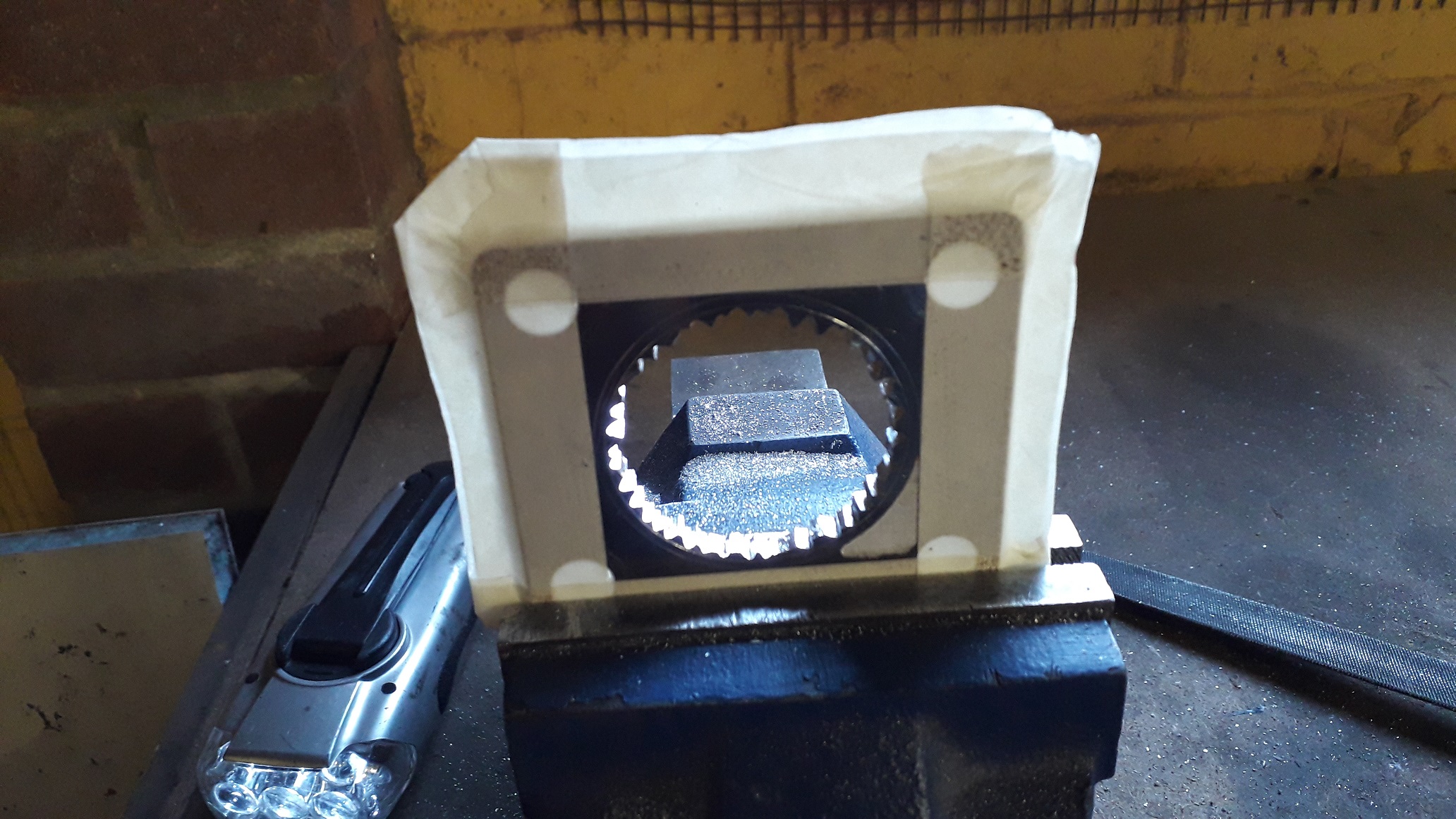
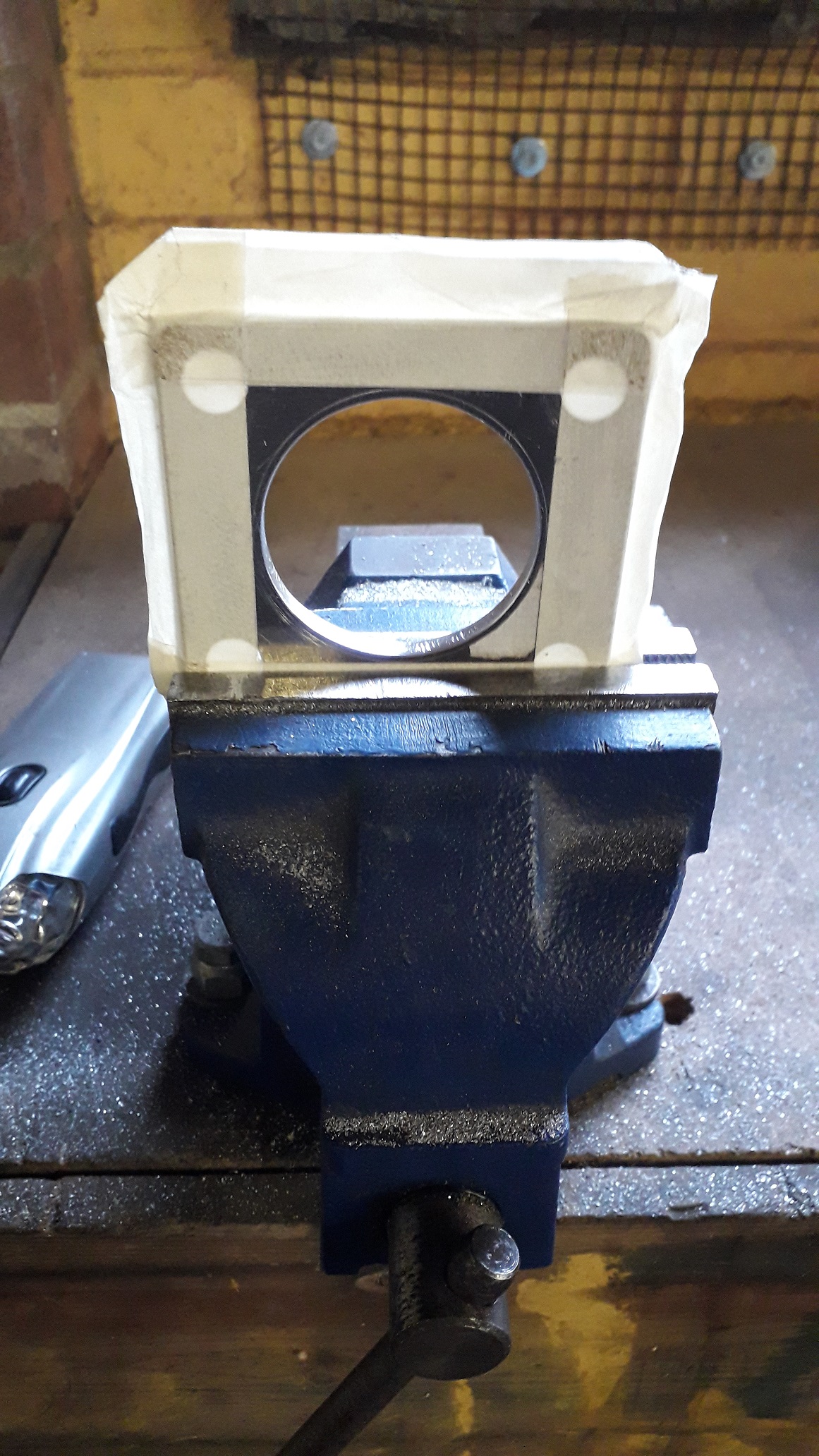
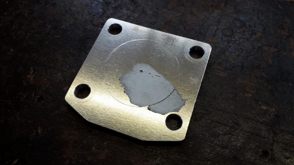
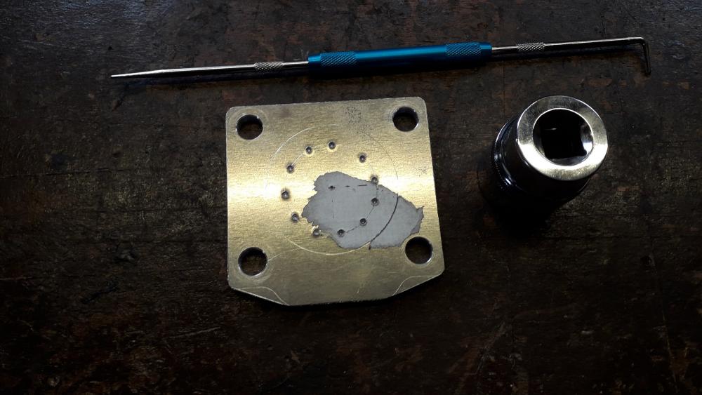
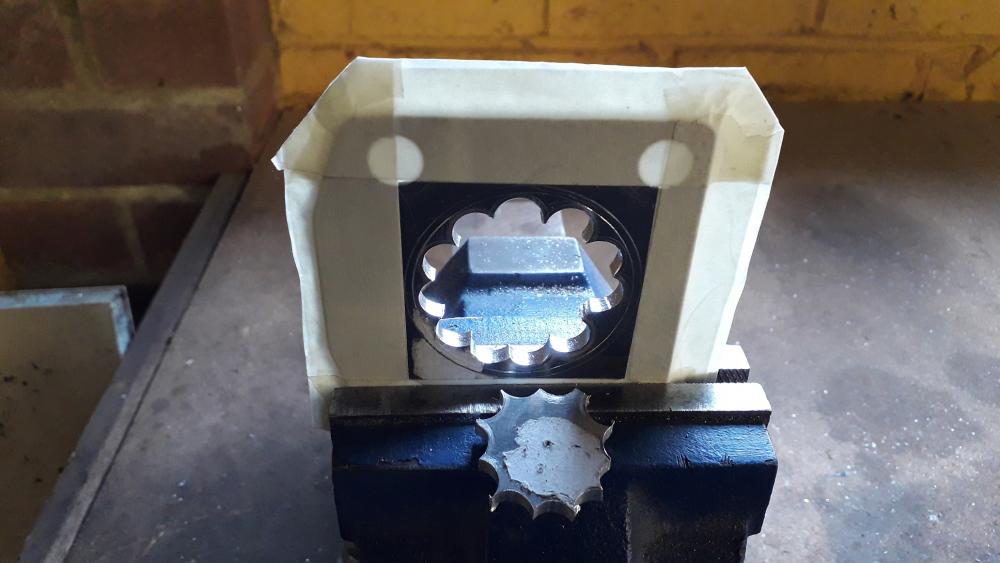
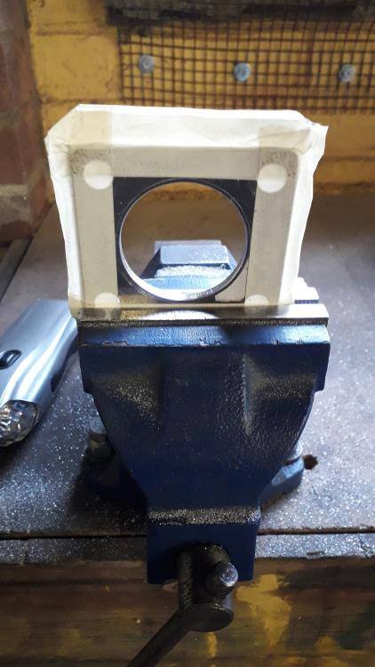
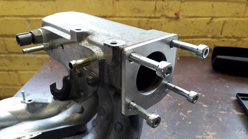
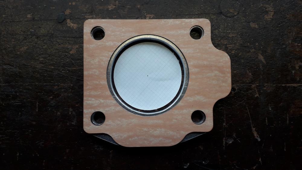
4efte inlet manifold throttle body plate. https://www.youtube.com/watch?v=nnosFMkKSOk The throttle body mounting surface of the 4efte and 4efe / corolla manifold differ in shape to correspond to the shape of the throttle body. So to fit a 4efe throttle body to a fte manifold requires an adapter plate making. Essentially it is the same outer size as the gasket with holes as required. Linished to 81mm square, I drew round the gasket for the lower edge detail and linished the corner features and also rounded the edges to approx. 3mm. Mounting holes drilled to 8.5mm Don't have the correct hole saw size available so old school chain drilling was the order of the day. Drew round an appropriate size socket for the drill hole PCD. Centre punched the drill points. Chain drilled the holes to 10mm and then scribed the throttle body hole onto the plate. Decided on 47(ish)mm as the manifold is 50mm and the throttle body is 45mm. Wrapped the edges in masking tape to prevent the vice marking the sealing surfaces. Sawed out the centre of the hole (this appears to have angered it!) Filed out to 48mm (ish). Smoothed the cut edges with wet n dry, and finished the sealing faces also to remove any deeper scratches it had picked up. Test fit to manifold, hole centres line up as does central hole. Gasket on, paper disc is 45mm to simulate throttle body hole. Plenty of clearance in the plate. Pleased with the results. All dimensions were within 0.5mm of requirement which is good for a hand made piece.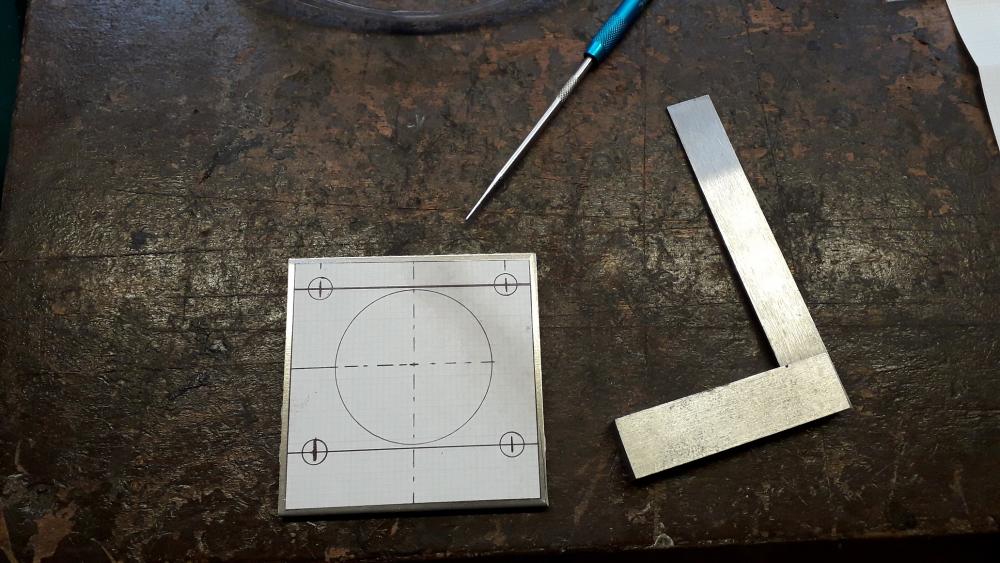


-
Bearing tolerance slightly too big - Incorrect bearings?
Claymore replied to bittenfleax's topic in 4E-FTE Engine Discussions
No problem . Sounds like a good build, feel free to start a thread in the owners progress section. -
Bearing tolerance slightly too big - Incorrect bearings?
Claymore replied to bittenfleax's topic in 4E-FTE Engine Discussions
As far as I can research, the bearing shells are thinner at the parting line (where you are measuring) and should be measured at 90 degrees to the parting line with a ball anvil in the micrometer to get their true thickness. I also thought that oil clearances are measured by installing the bearing shells in the main journals and caps, adding the caps and torqueing them down. Then measuring the the central bore with a bore gauge at 90 degrees to the parting line? This gives the size of the bore with bearing installed to check against the crank main journal size to check the oil clearance? Never done it myself though. -
Looking good. 😎
-
Just purchased a forged Glanza anyone know it?
Claymore replied to MantisTobbgan's topic in Welcome New Owners!
Don't know the car, but glad to hear you found one. Don't forget to start a build thread to show of your new toy. -
Radio harness no power - need help
Claymore replied to starlet1991's topic in 4E-FTE Engine Discussions
Taken from 96/97 European EP91 Toyota Electrical Manual. Speakers: RR+ = Red, RR- = white, RL+ = Black, RL- = Yellow. FR+ = Light green, FR- = blue, FL+ = Pink, FL- = Violet. Power: Constant 12v = blue with yellow stripe, acc 12v = grey, gnd = brown. Constant 12v from 10A Dome fuse (engine bay fuse box), acc 12v from 15A Rad & cig fuse (fuse box under steering column). *Can't find reference to the dark green wire though? -
Claymore's sleeper 4efe+t-t+t build (R.I.P. the Nanza)
Claymore replied to Claymore's topic in EP91 Progress Blogs
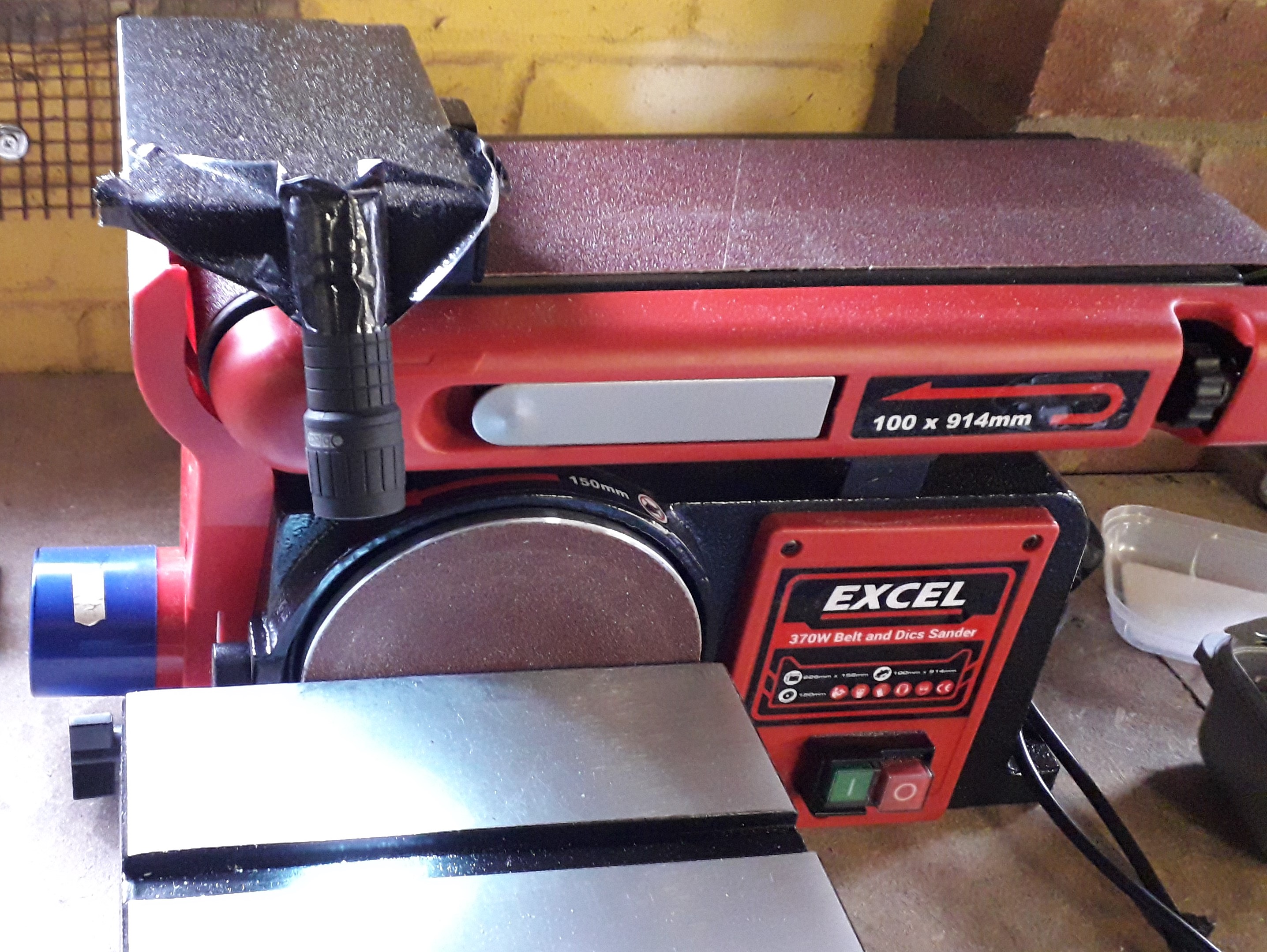
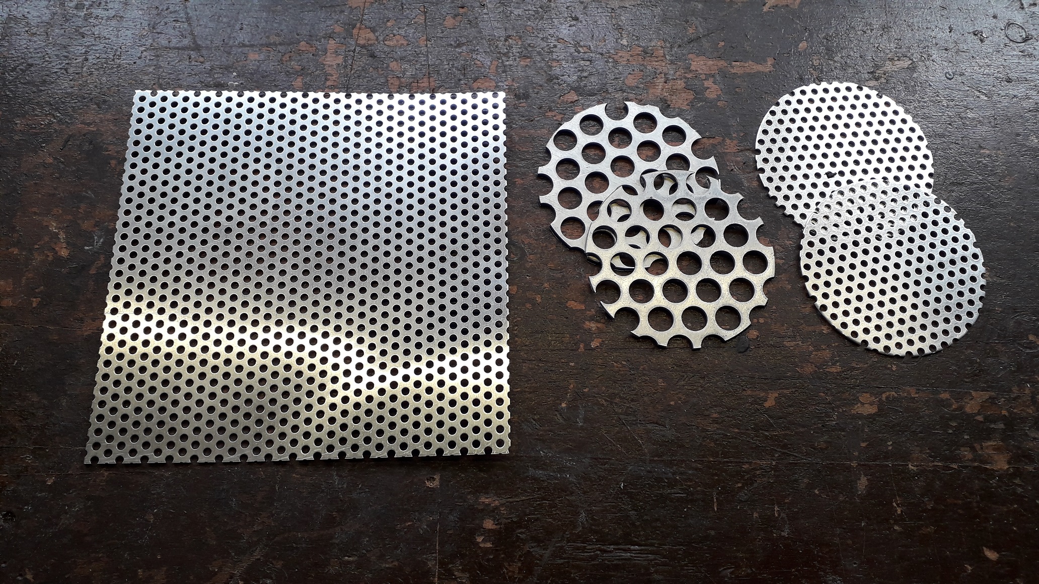
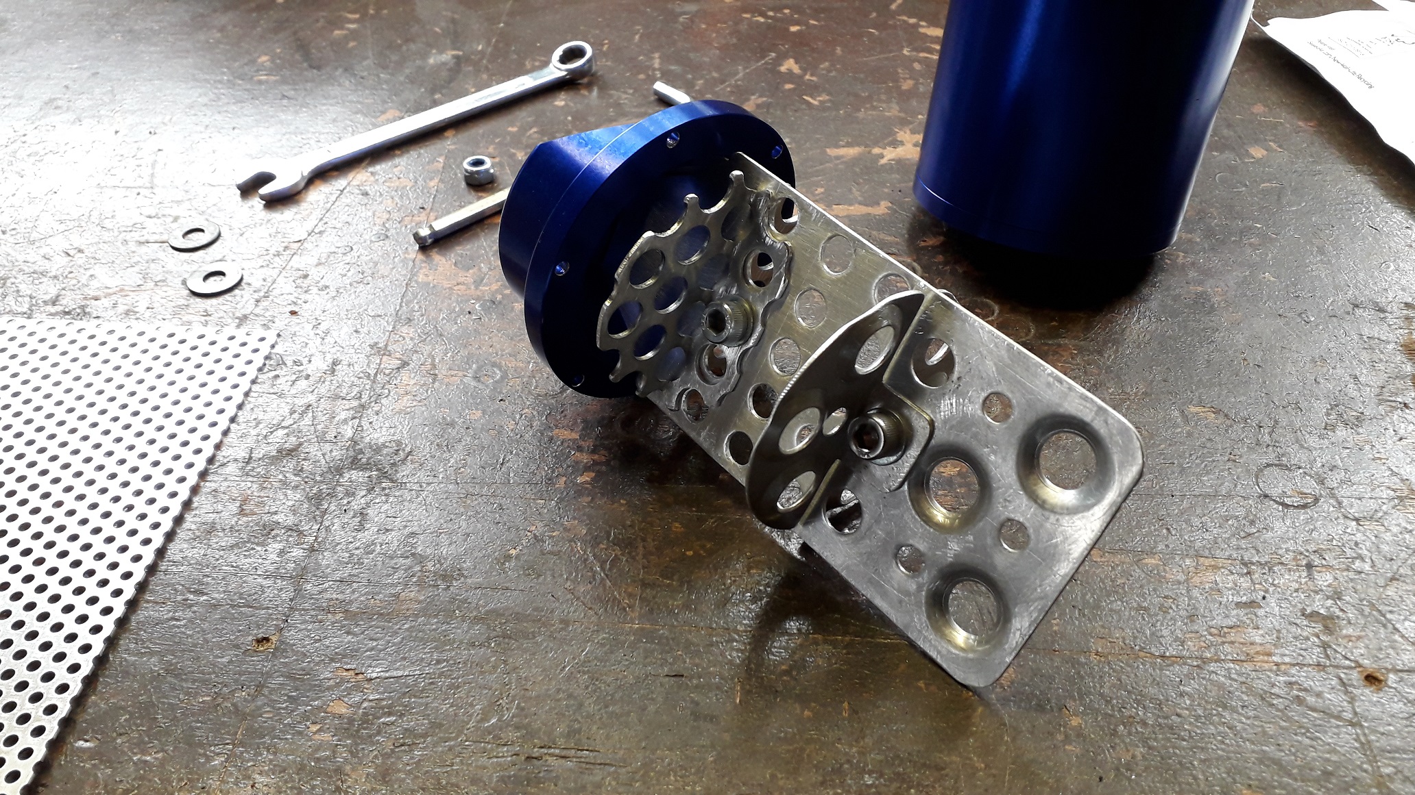
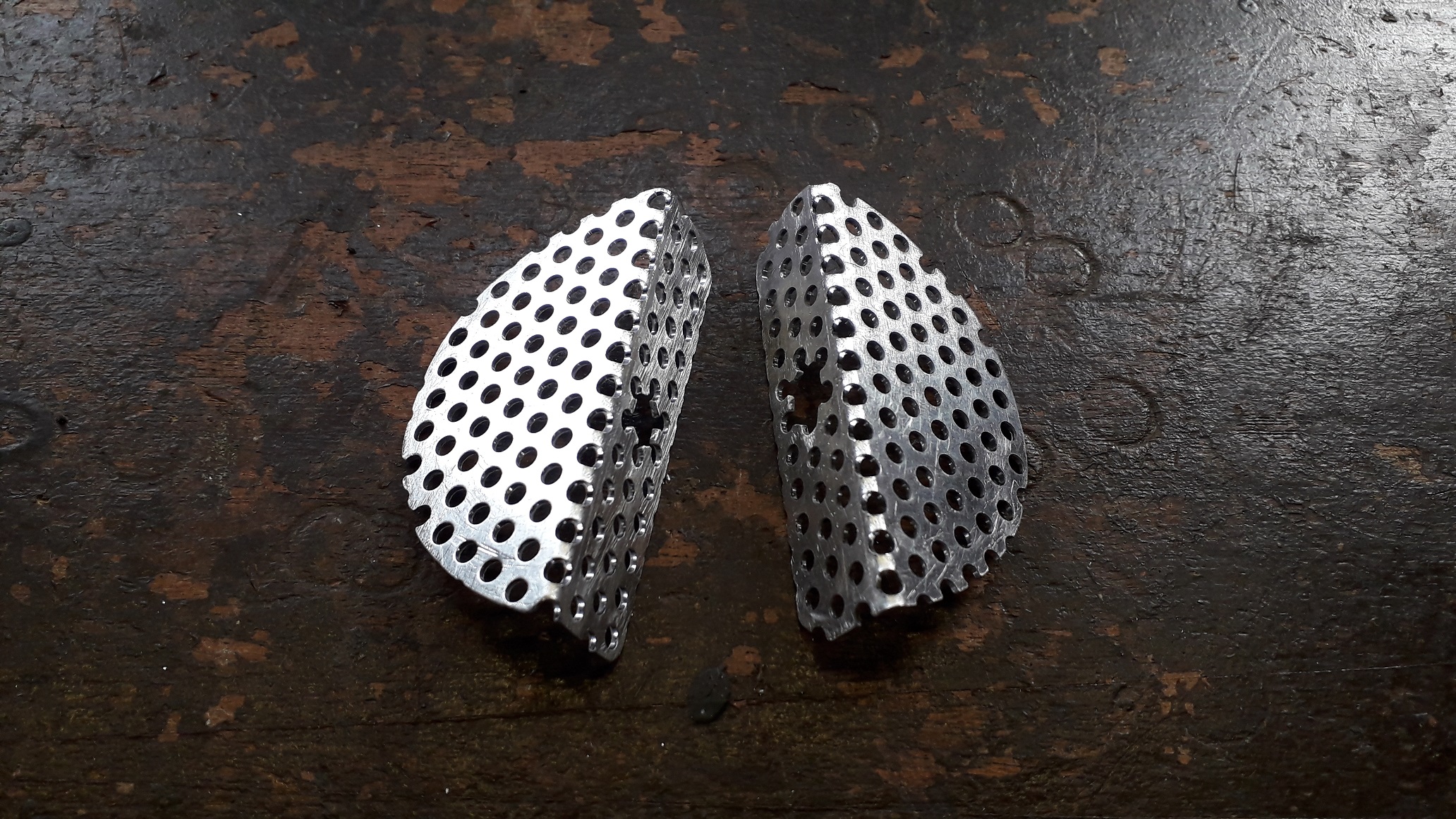
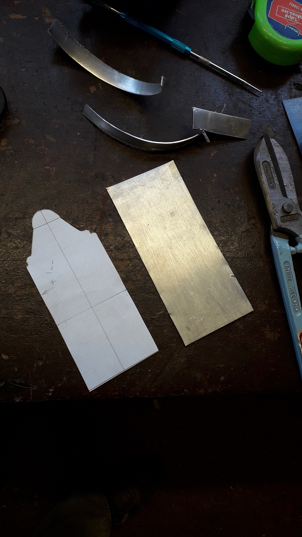
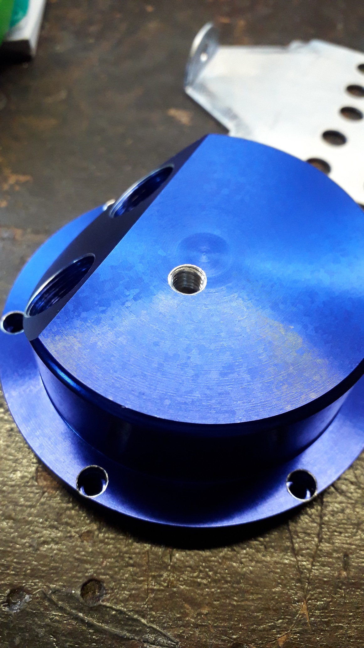
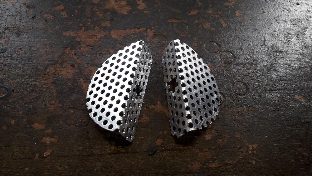
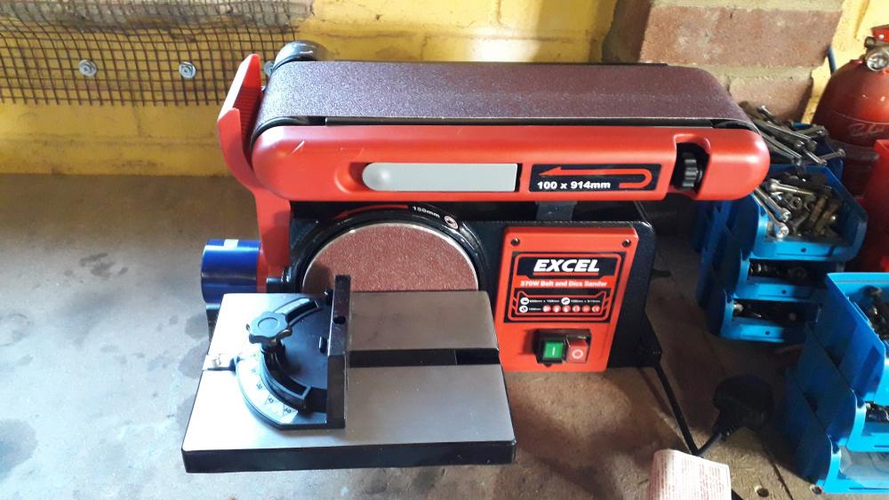
I added more baffles...... Treated myself to a new toy for the workshop. It's the generic Chinese disc / belt sander combo that is for sale under many different brands. Deffo not industrial strength but more than capable for hobby level machining. 370w motor, 150mm disc and 100mm wide belt with a usable 100 x 300mm area. (tilts too). Will be a great replacement for the man powered files I've been using for the past 20 odd years! So with the new capabilities bolted to the bench and the Claymore industries patented dangle poise lamp temporarily installed, I set about making some pieces of metal smaller. Bought some perforated sheet to save the additional work of drilling the holes myself. 1.1mm alu sheet with 3mm holes and 1.5mm alu with 10mm holes. Not so many photos this time, but I chose the central hole on one row of the mesh disc as the fixing point and used this as my datum to mark out the shape. Cut out roughly with tin snips, sanded close to shape and finished off by hand. Folded in the vice. Bolted to top row of central baffle holes. Did the same with the 3mm perforated disc. The only problem that arose was when drilling the mounting hole it breaks through into the existing holes making a "petal" shape, easily covered by a large washer but I don't really like bits that small. Once mounted in the can it provides another surface to condense vapours upon without impeding flow. May try the 3mm baffle version instead or as well as depending on how this version performs. Deffo quicker to make the parts this time around.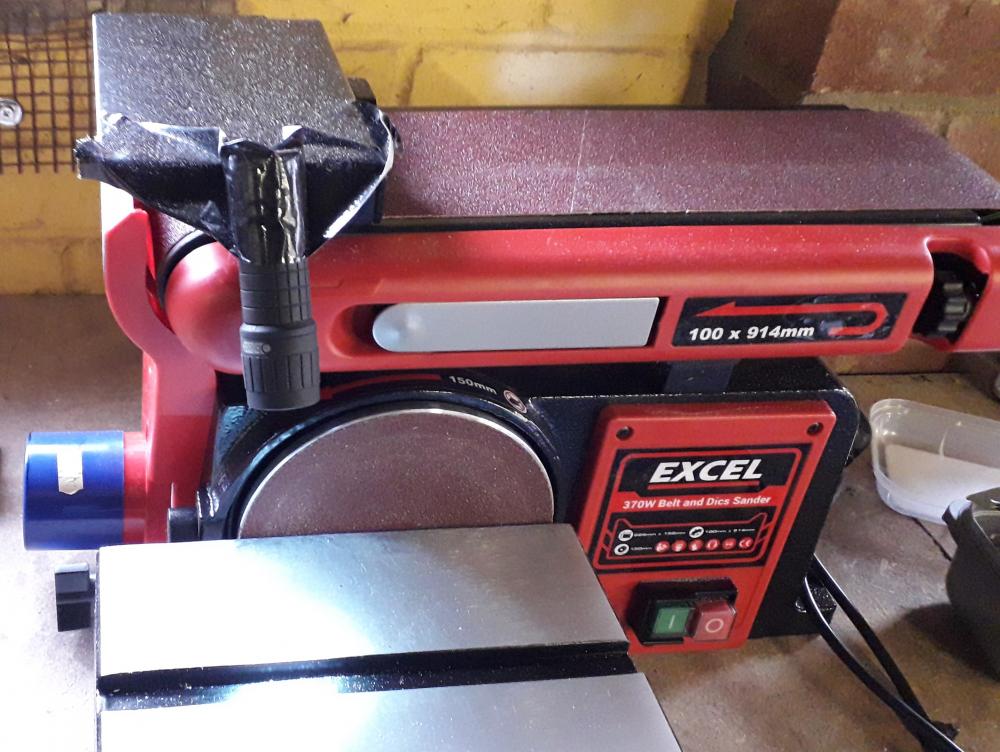


-
4efe SWAP to 4efte in Corolla E11 1998
Claymore replied to Frankieflowers's topic in 4E-FTE Engine Discussions
Sounds complicated and expensive. Stick with the original plan in my opinion. Please remember this is a starlet forum, people here have helped the best they can and spent lots of time guiding you (and on the other forum as well). Its your choice and your money, but starting again seems like all the previous 8 pages of this thread are now a waste of time? We all have these fantasy moments but please, remember your budget, time allowance and fabrication skills. The 4efte corolla 2wd will be awesome anyway. Keep it simple mate. -
Now that's a turbo! Should spool well with the smaller back housing. What size is it HX?? Great fabrication /machining as always.
-
4efe SWAP to 4efte in Corolla E11 1998
Claymore replied to Frankieflowers's topic in 4E-FTE Engine Discussions
Not too difficult. Just don't scratch the crankshaft, oil pump or sealing collar or it will leak oil. The front seal comes off with the oil pump when you change the pump so is easy to install after the new pump is on. There are special tools to remove crankshaft / camshaft seals with the shaft still in place. Much easier / cleaner and safer than the old "sheet metal screw and pull technique" -
Any time
-
Glad to see you got the 5e mate. Looking forward to the updates. Top class build
-
Great to hear mate, looking forward to the updates
-
4efe SWAP to 4efte in Corolla E11 1998
Claymore replied to Frankieflowers's topic in 4E-FTE Engine Discussions
Most of the "official" workshop manuals say to take the valve cover off. But most of the guides I've seen on the forums / internet the cover stays on and you only need to work from the side. With the 4e-fte out of the car on an engine stand it will be very easy to change compared to when it is installed in the engine bay. Don't forget to change water pump and most likely oil pump as well as the crank seals etc.... You might want to check under the valve cover anyway when you get the engine, you can check the shim clearances to the cams and also check that the camshaft lobes aren't chipped (See RoyalDutchies build thread). Also it will show if there is oil sludge and varnish showing how well it has been maintained. -
Claymore's sleeper 4efe+t-t+t build (R.I.P. the Nanza)
Claymore replied to Claymore's topic in EP91 Progress Blogs
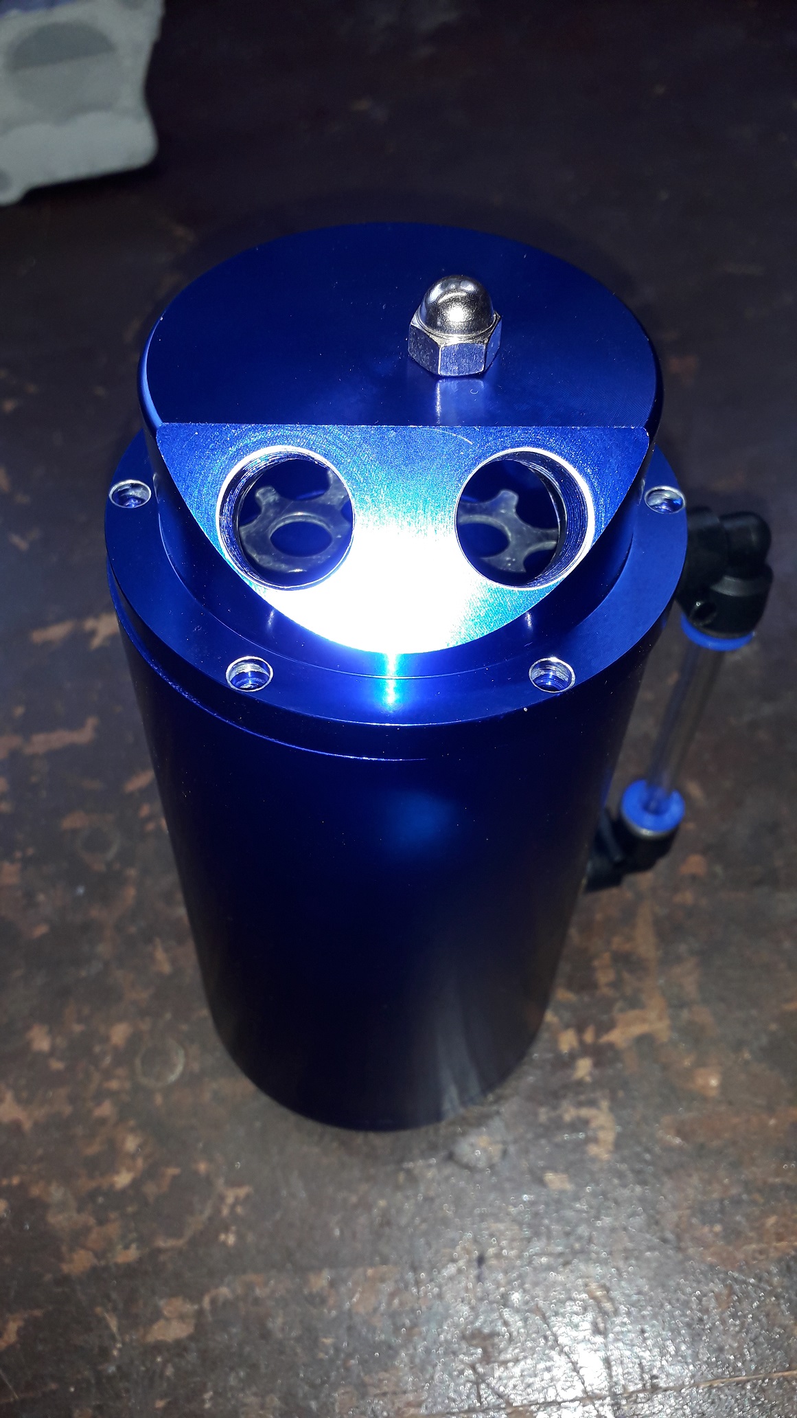
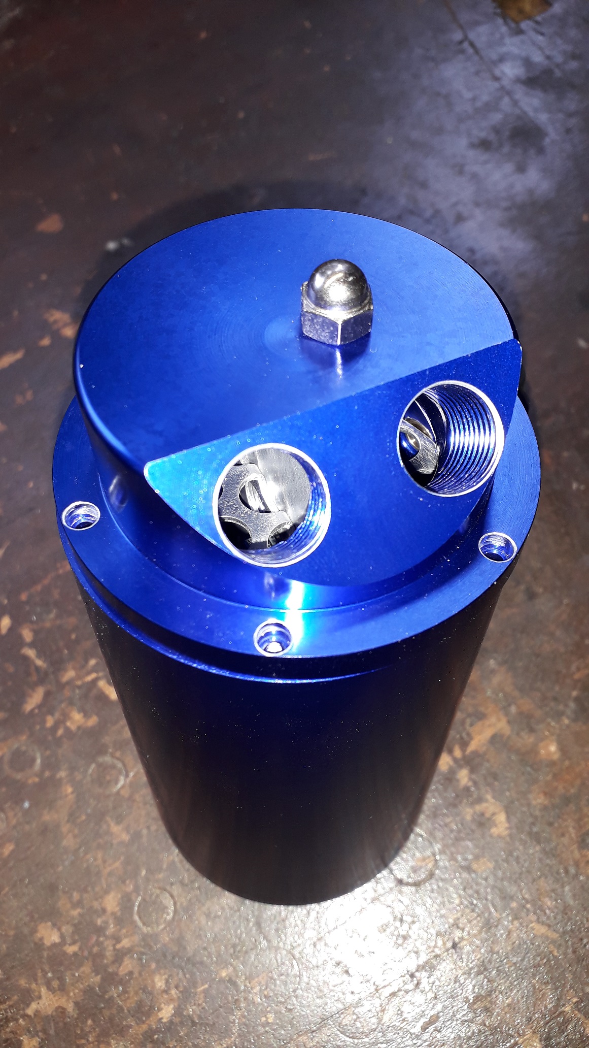
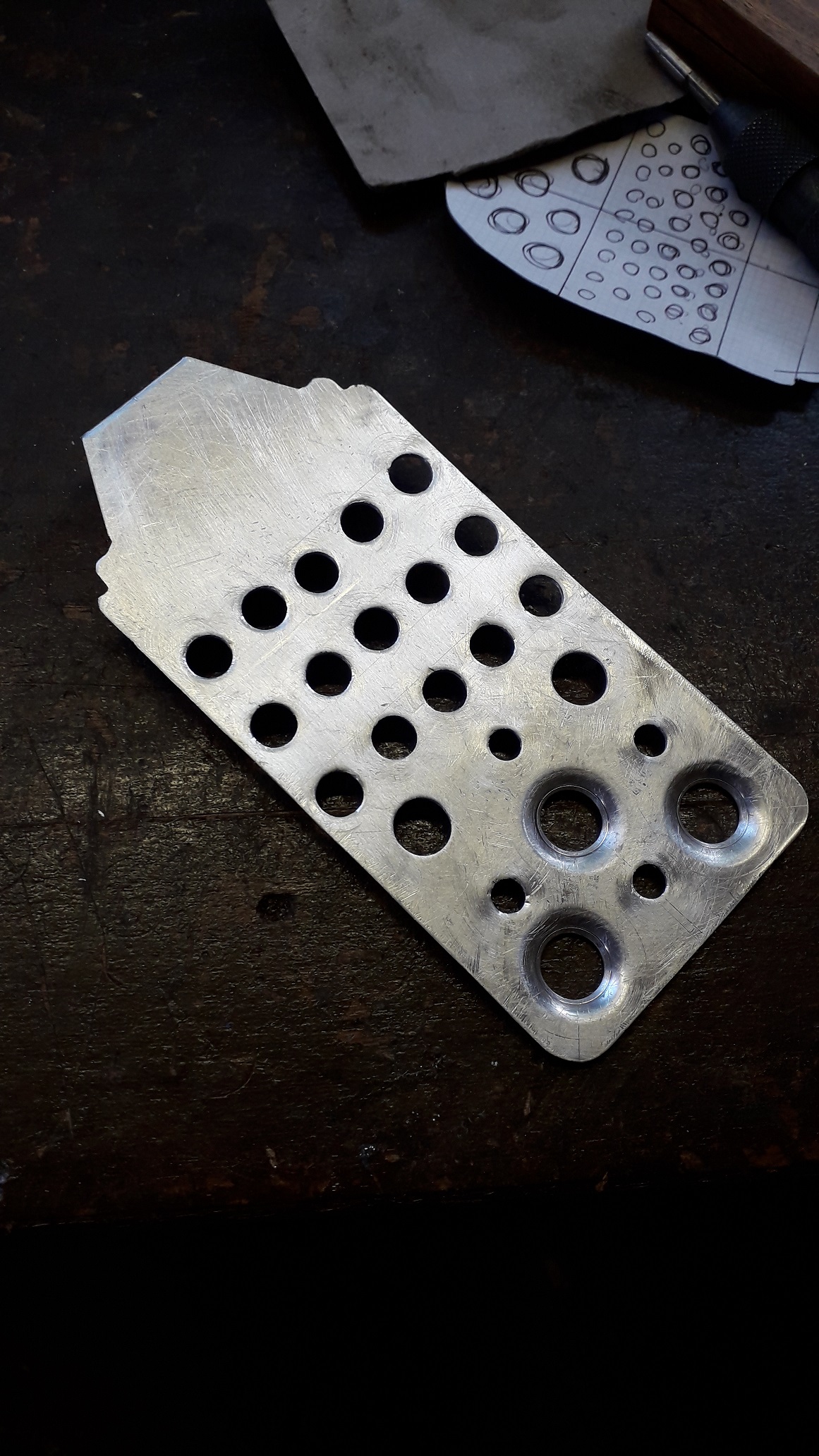
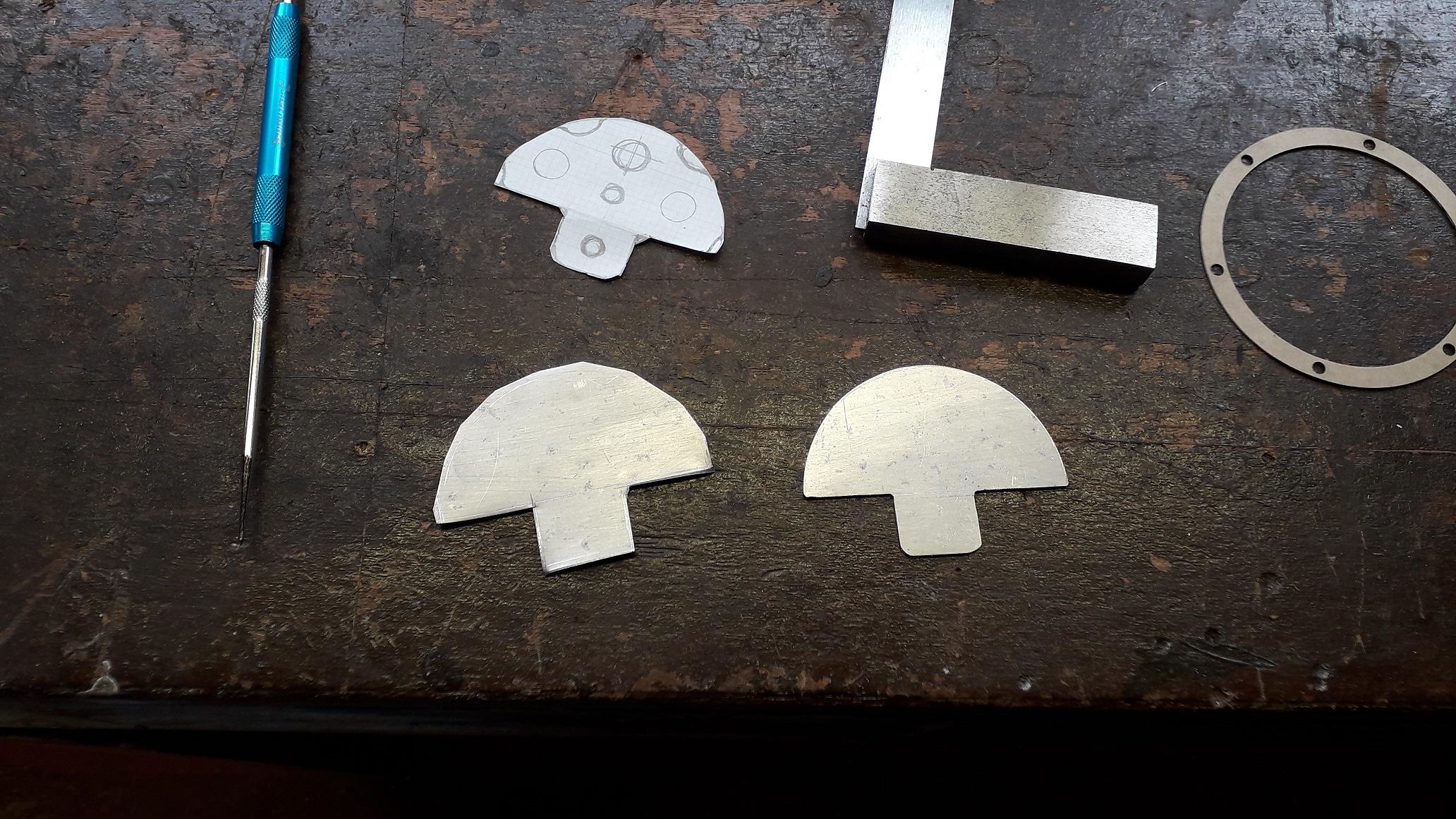
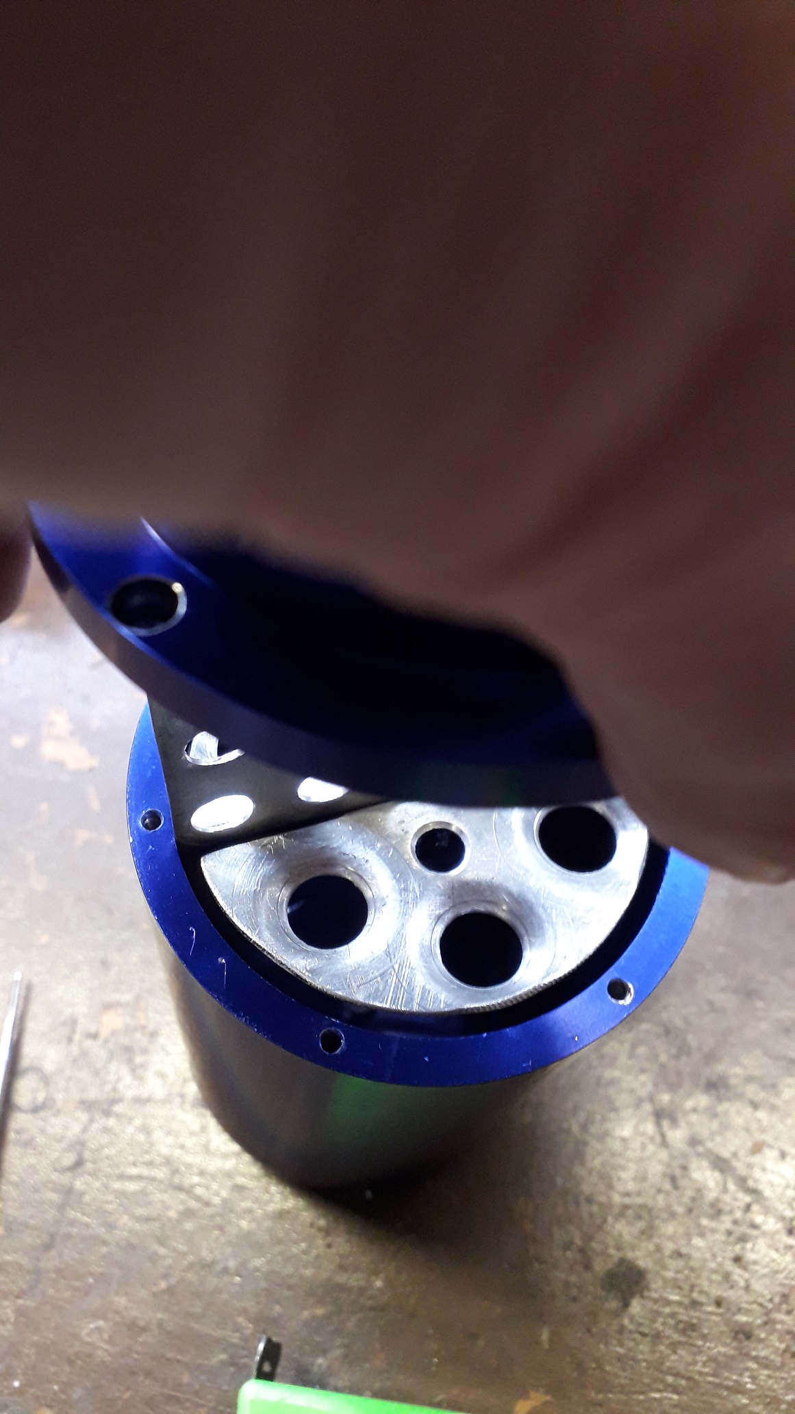
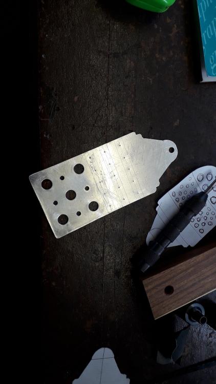
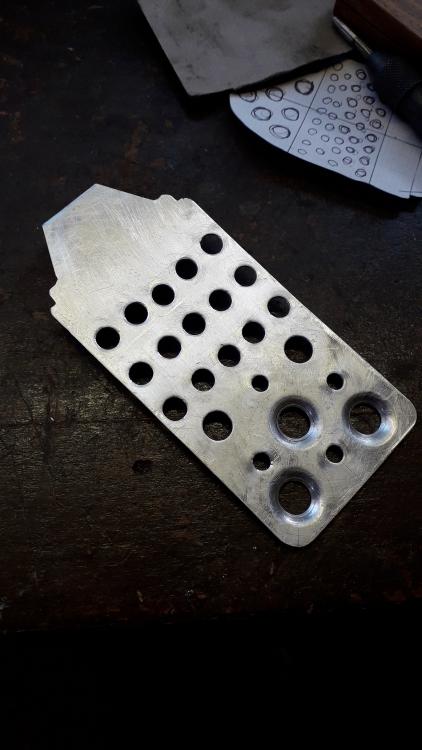
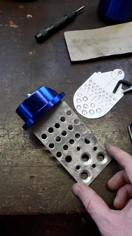
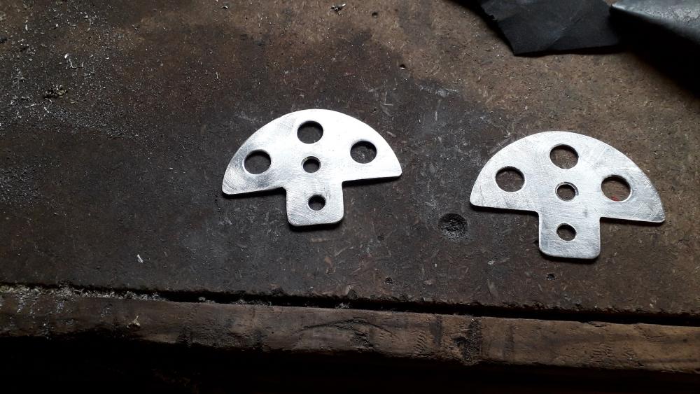
Catch can baffle As the can was completely devoid of any baffling I decided to separate the can in half with a central divider baffle, with some lower horizontal baffles. Didn't fancy using stainless scourers (too much chance of shrapnel) and as the flow through the can will have to change direction it needs to be able to flow both ways. Also needs to produce as little pressure drop along the way as possible. Off boost, clean air is drawn from the intake pipe pre turbo, through the can and into the the crankcase and onto the intake manifold; on boost the PCV shuts and crankcase vapours are drawn out through the can (where the oil and water droplets are separated from the air) and into the intake pipe pre turbo. Same as stock setup with the addition of catch can. Made a paper template on graph paper and cut a blank from a piece of scrap alu I had lying around with tin snips. Marked out an drilled the lower holes, these will be used in the lower 3rd of the can to reduce the liquids captured from sloshing around under cornering and accel / decel. Marked out some more holes. Drilled the holes I marked out and hole swaged some of the lower holes for added strength to the relatively thin plate of alu. Drilled and tapped the lid to accept the central baffle fixing screw. Needed all the thickness available hence the thru hole. Also allows the use of a longer screw to attach a lock nut on the outside (belt and braces). Test fitted to lid. Made some lower baffles using the card gasket as a template. Marked and drilled said baffles. Then went onto fold the tabs in the vice and swage the larger holes for strength. Assembled the lower baffles to the central baffle. The idea is that oil vapours enter the can on one side of the central divider flowing down and have to turn 180 degrees whilst travelling through the holes and exit the can on the other side. During the turn some larger contaminants will be thrown from the air (centrifugal force) and the remaining vapours will condense on the can / plates and baffles. The horizontal baffles are more to keep the liquids restrained but also offer additional surface area to condense upon. These baffles can be mounted higher up towards the solid baffle section if needs be. Test fit no. 47 into can, finally filed to shape with minimal clearance all round. Ready to be cleaned, before final assembly. Should perform better than the empty can I started with. Can always add more baffles if required.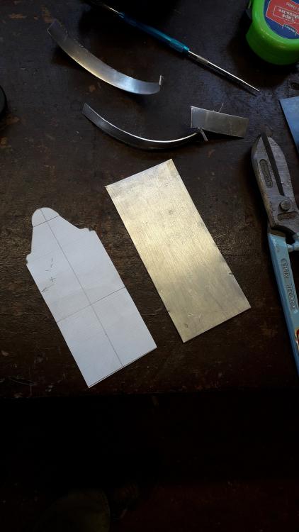


.jpg.8a7d1f5ae223a54d05f40ba8a39b8e3a.jpg)