Claymore
-
Posts
660 -
Joined
-
Last visited
Content Type
Profiles
Forums
Wiki
Media Demo
Events
Everything posted by Claymore
-
Claymore's sleeper 4efe+t-t+t build (R.I.P. the Nanza)
Claymore replied to Claymore's topic in EP91 Progress Blogs
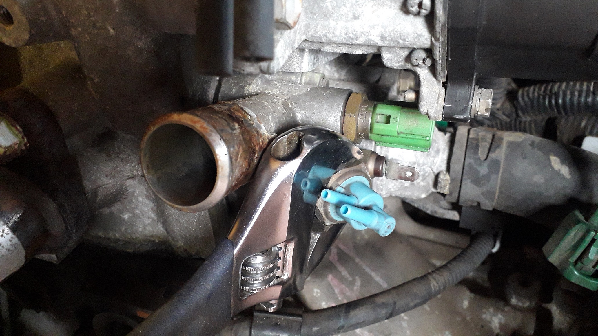
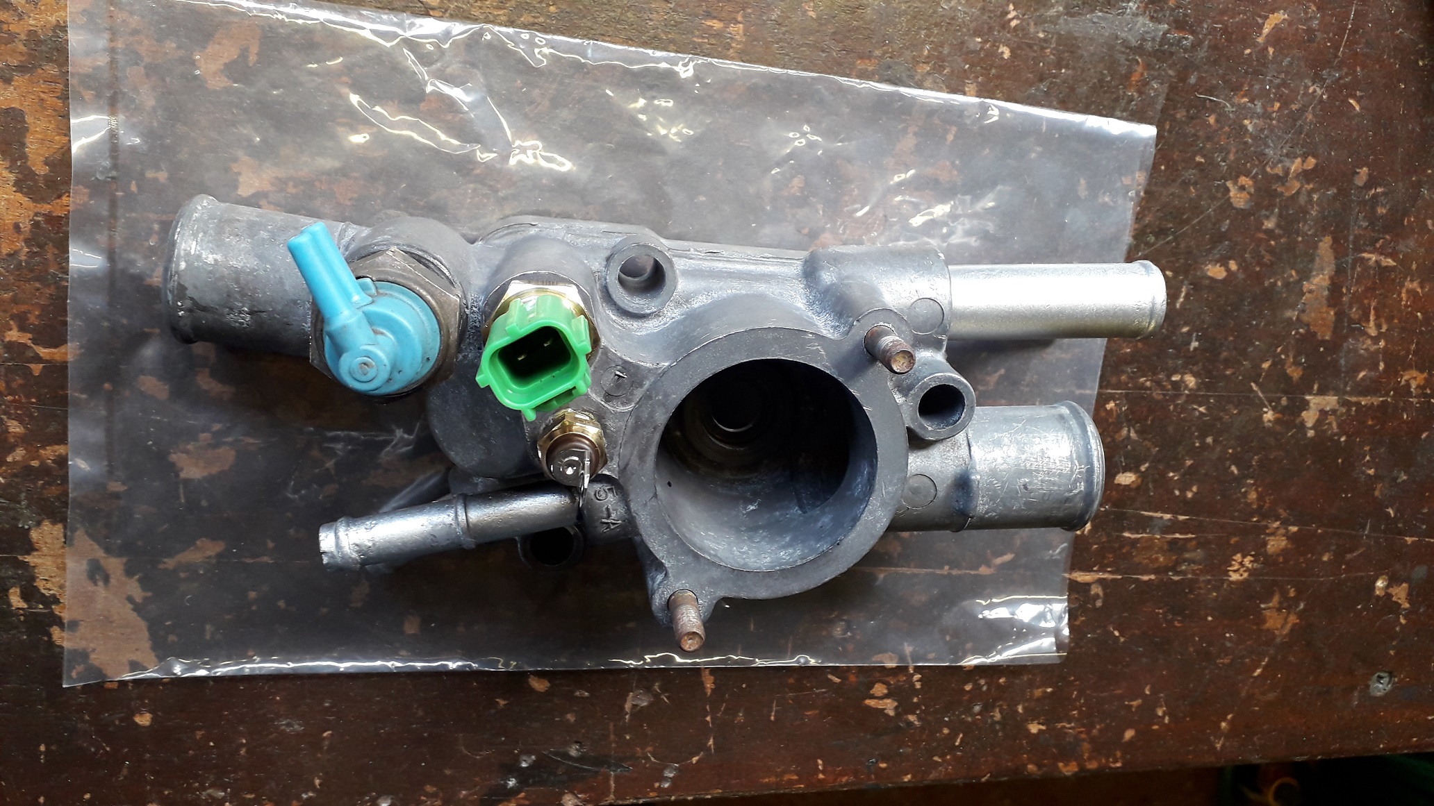
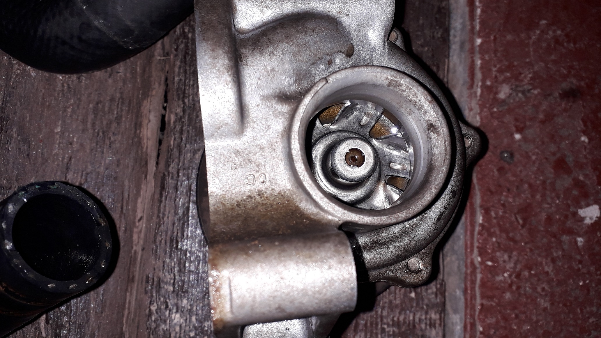
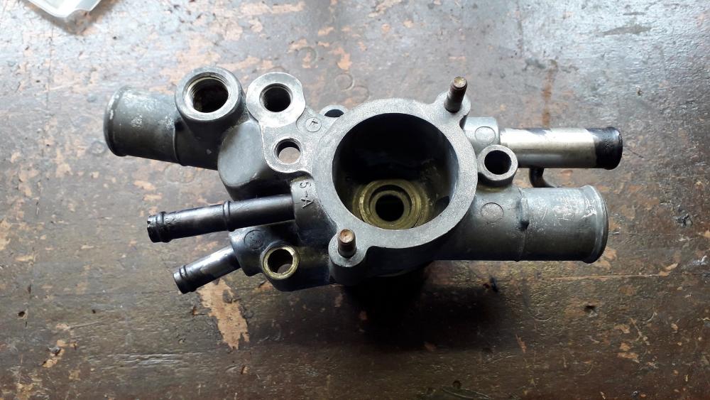
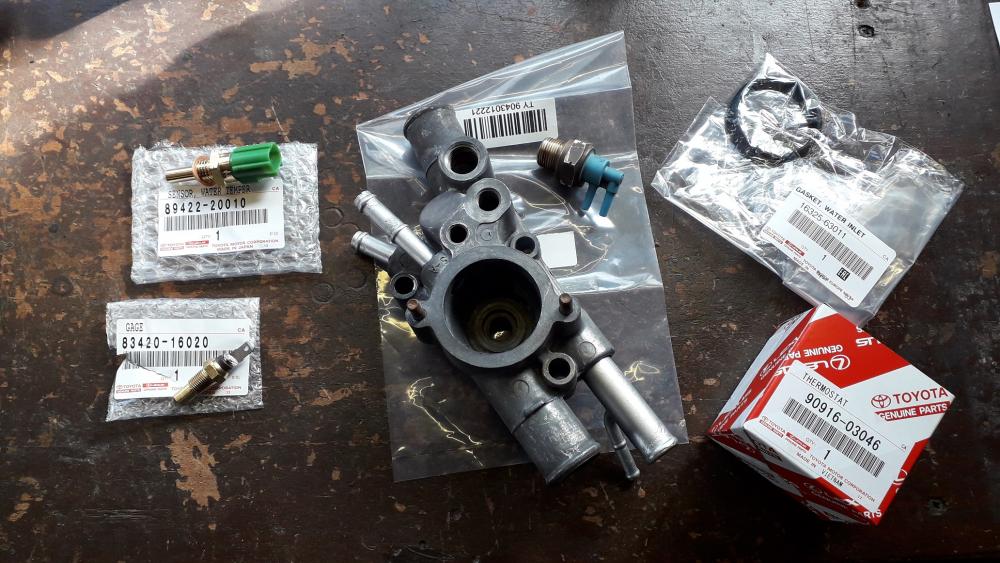
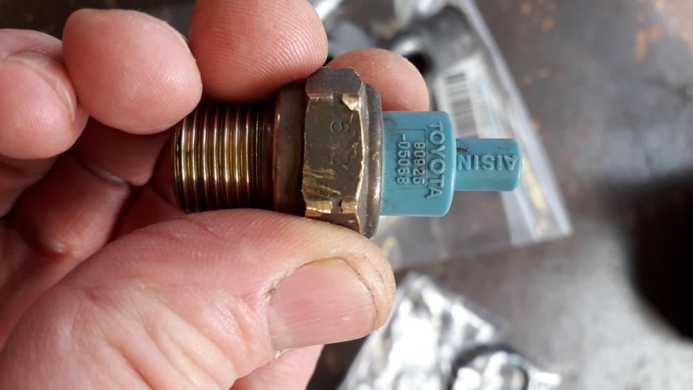
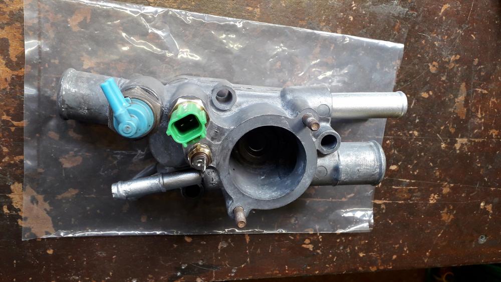
Cooling system mods continues.... With the water pump on it was time to work my way round to the water outlet / thermo housing. Managed to buy an early style 4efte water outlet from Sam44 seemingly months ago now. The early style has the 2 separate thermo sensors for the ECU and instrument gauge. This will provide the coolant feed for the turbo. After a clean up, and I also removed the blanking plug (tapered thread again), don't usually use the cordless impact on things but it was virtually impossible to hold the cast alu housing safely so after some tense moments with rattle gun it was out, housing unscathed. This port was now available for the fitting of the TVV valve (thermo operated valve) to retain the charcoal canister system for emissions control. New sensors and thermostat, genuine Toyota. Part numbers in pictures. The ECU thermo sensor has a copper washer to seal to the housing and the other 2 sensors are taper thread and I like to apply Loctite 577 for good measure. Sensors in, Started the install from left to right for clearance to each other and for spanner room. Ideally the TVV ports should be pointing at the 9'oclock position. https://www.youtube.com/watch?v=dC7z5eIff34 New seal on and thermostat installed, cap nuts tightened to 5Nm. The unit is ready to install.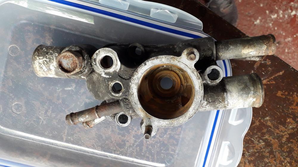

-
Claymore's sleeper 4efe+t-t+t build (R.I.P. the Nanza)
Claymore replied to Claymore's topic in EP91 Progress Blogs
Sounds like a real challenge mate, the access is easier for sure with the manifold off but will probably take the same time as doing it from underneath. Not a job I would want to do again this year! -
Claymore's sleeper 4efe+t-t+t build (R.I.P. the Nanza)
Claymore replied to Claymore's topic in EP91 Progress Blogs
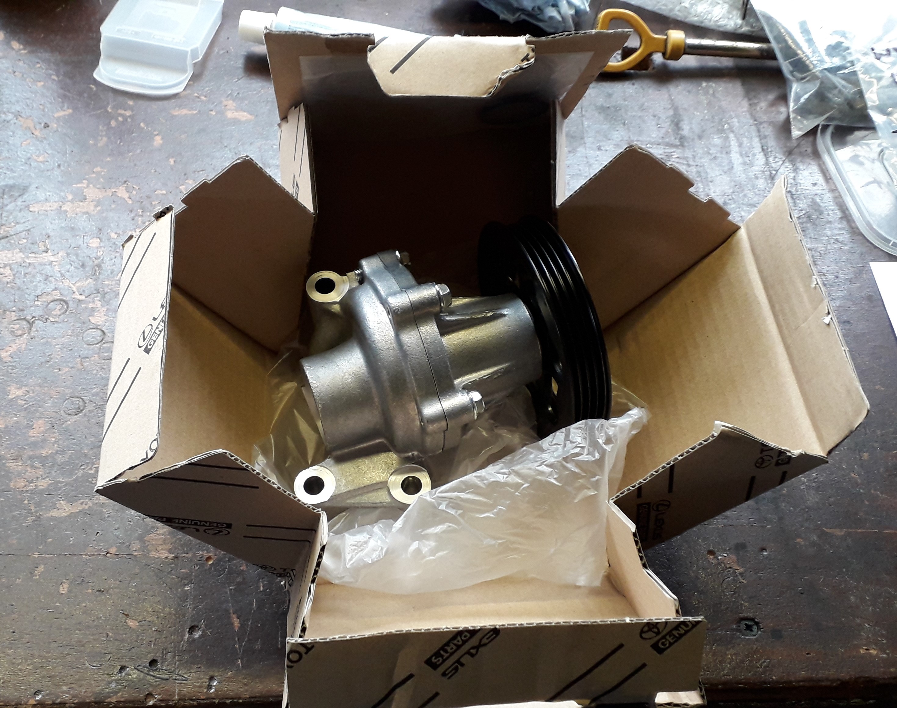
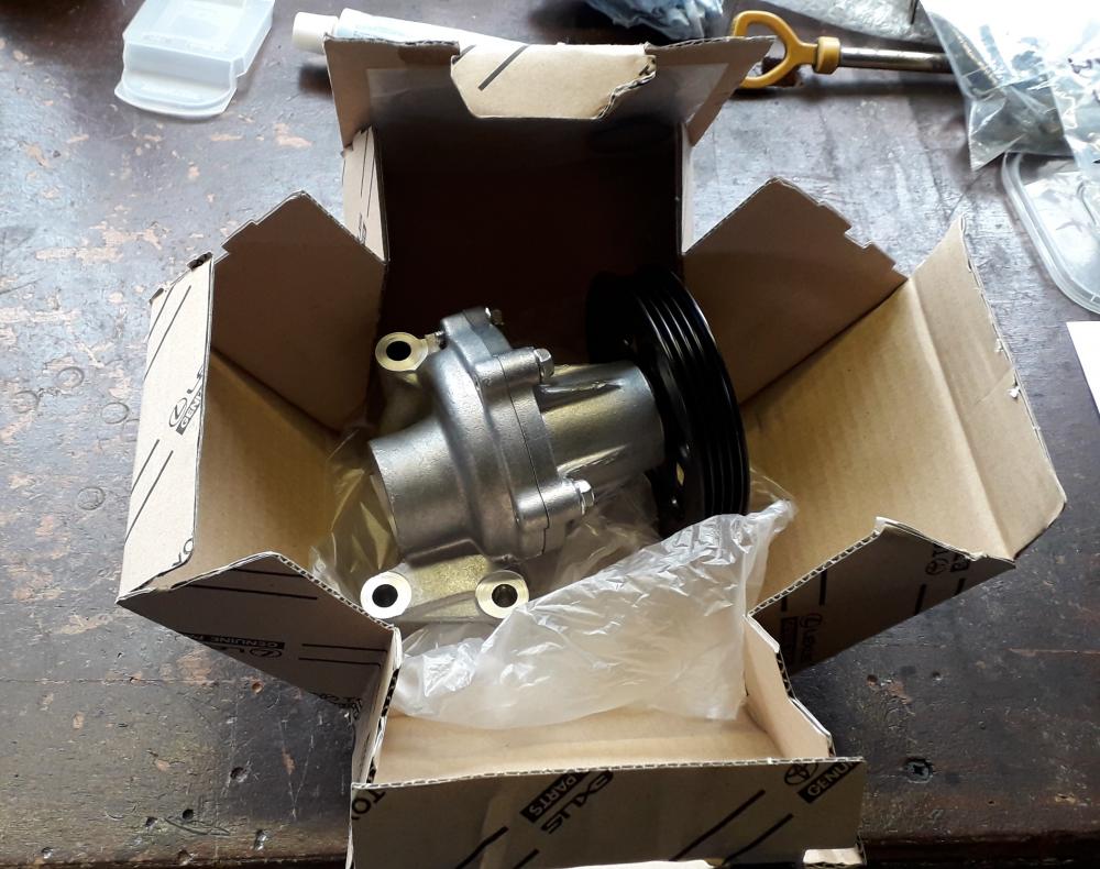
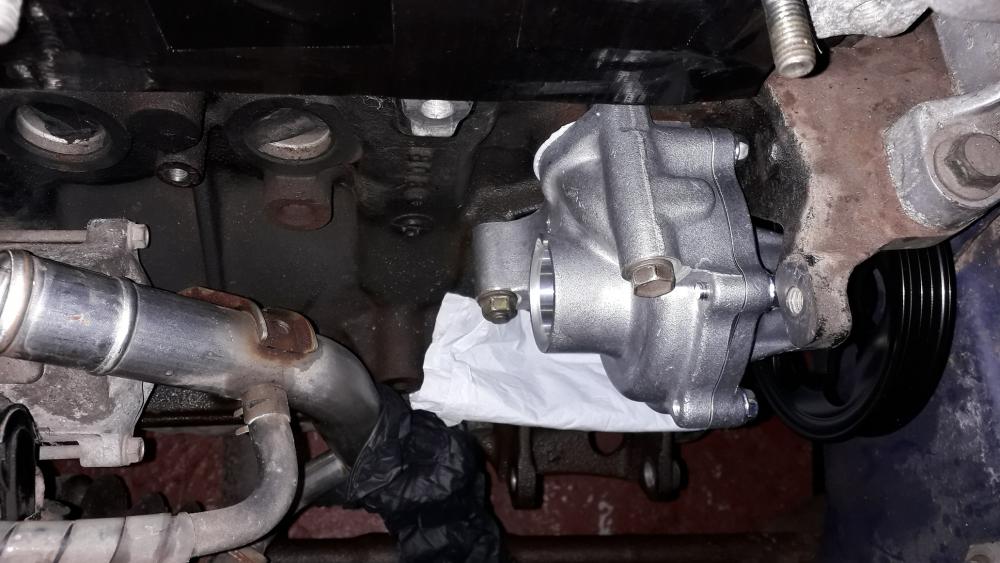
Water pump install. Bought a complete water pump and housing assembly from Toyota. No pattern parts bullshit this time! Part number is 16100-19226. Even the box is awesome! It consist of the pump, housing and the O-ring for the water pipe. Wrapped in a sheet of anti-corrosion paper, then in a plastic bag then boxed. Not many photos of this stage as it was time sensitive due to the sealant. I applied a bead of sealant (Elring Dirko) to the circular groove in the pump housing face and on the face next to the groove. Inserted the top securing bolt and slid the pump housing down the 2 x studs that Toyota cleverly installed in the block to guide the pump towards the block. Started screwing the top bolt in and the loosely attached the 2 x nuts to the studs. Pressed the housing to the block making the seal and tightened the fasteners evenly to a torque of 18Nm Gonna let the sealant cure and then rebuild the rest of it.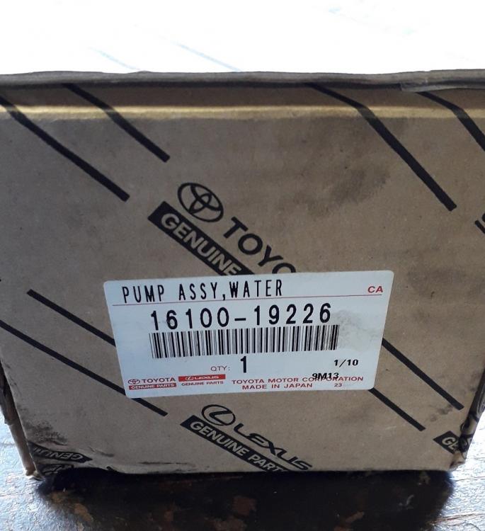
-
Claymore's sleeper 4efe+t-t+t build (R.I.P. the Nanza)
Claymore replied to Claymore's topic in EP91 Progress Blogs
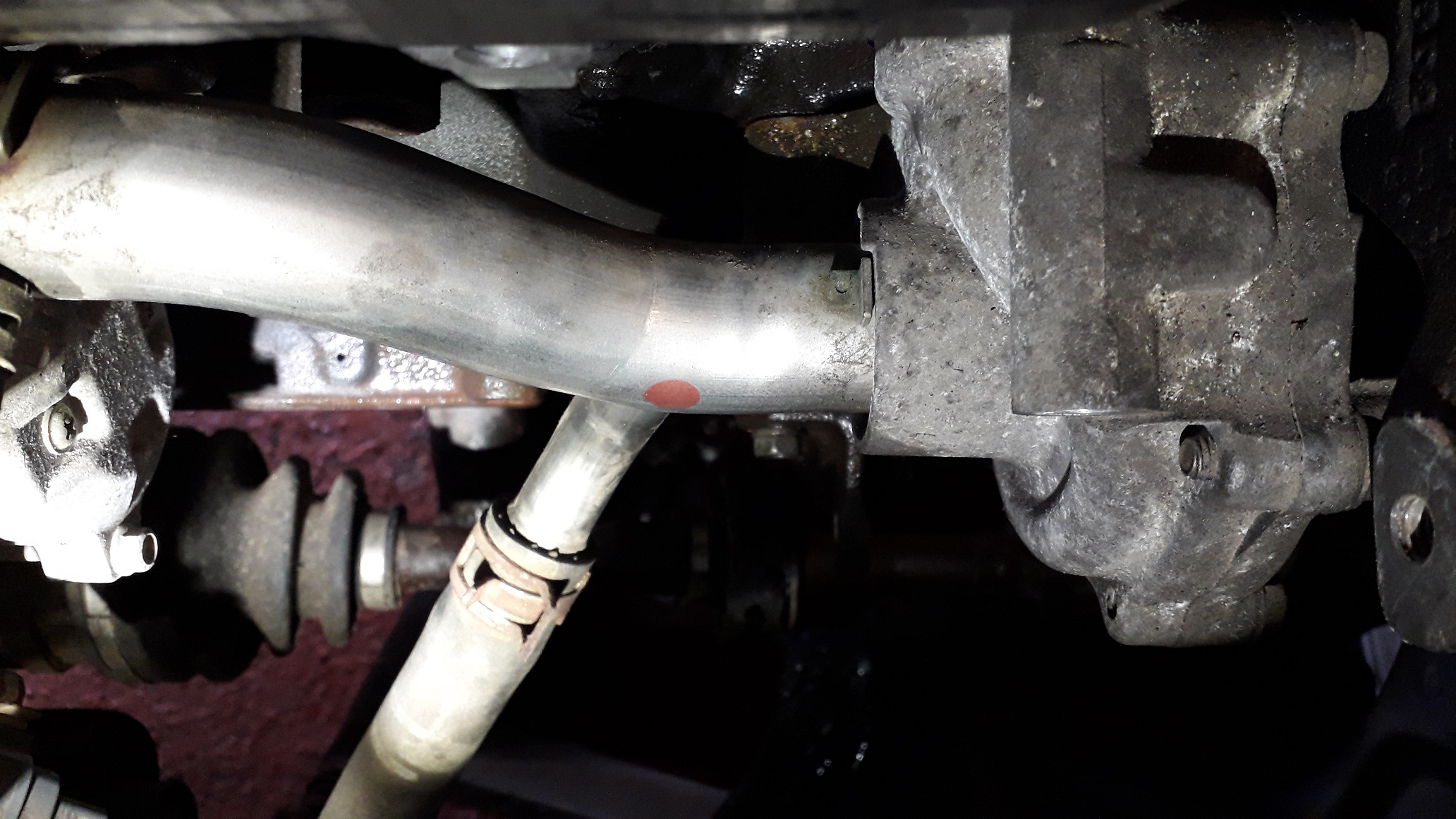
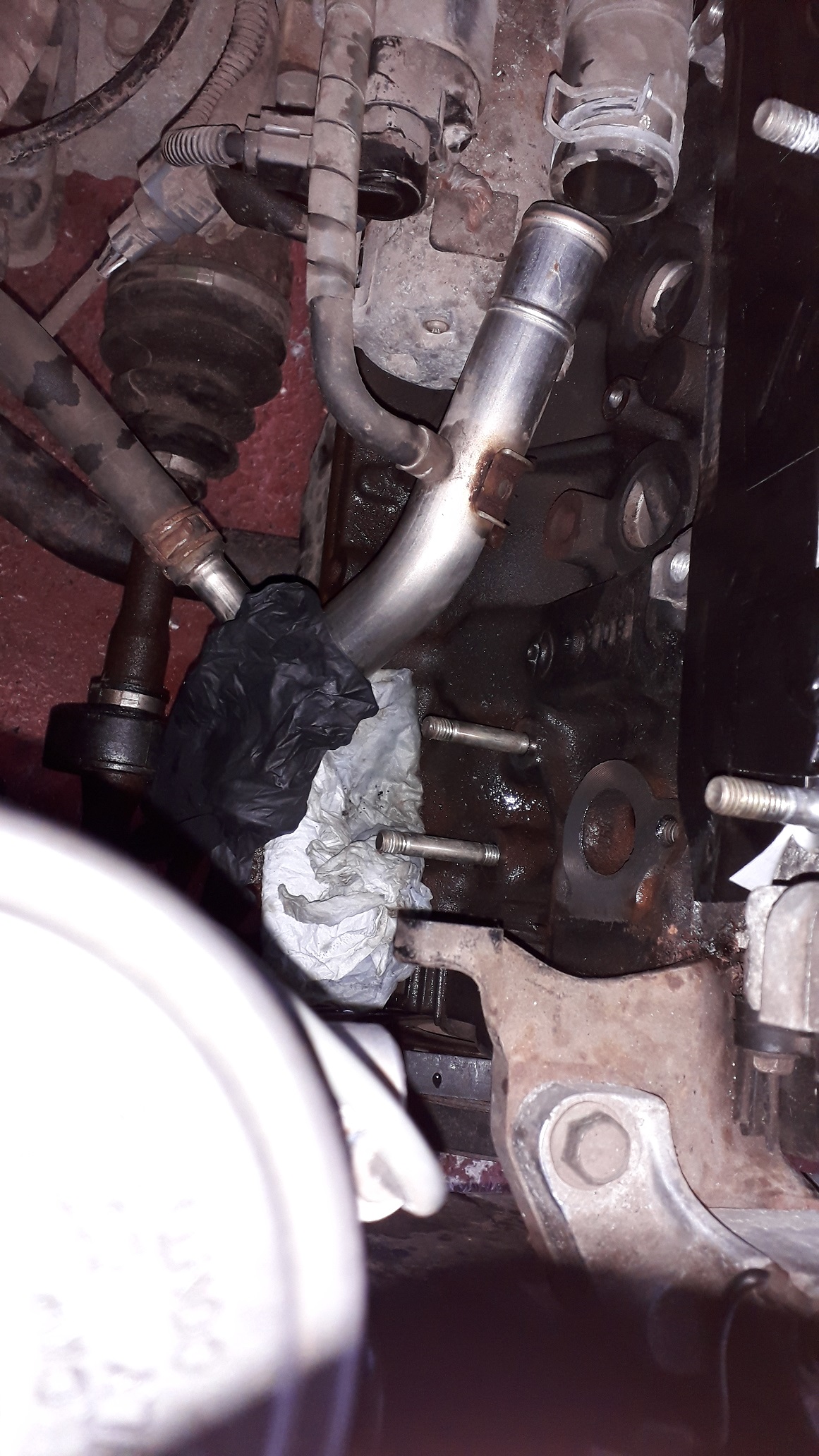
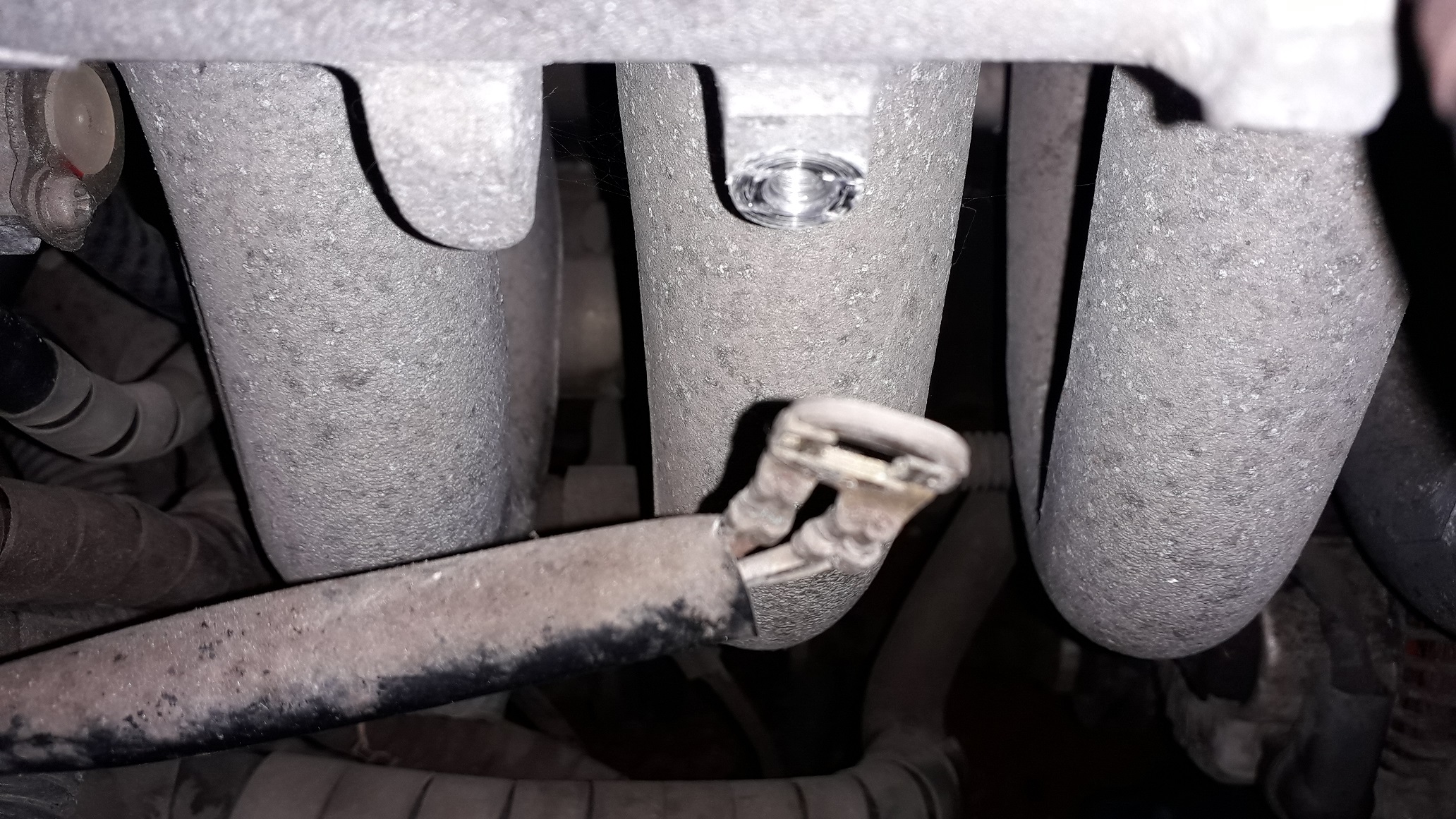
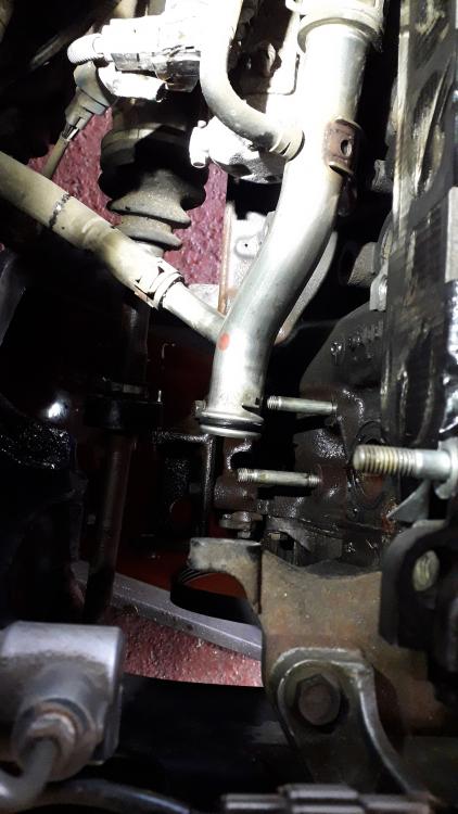
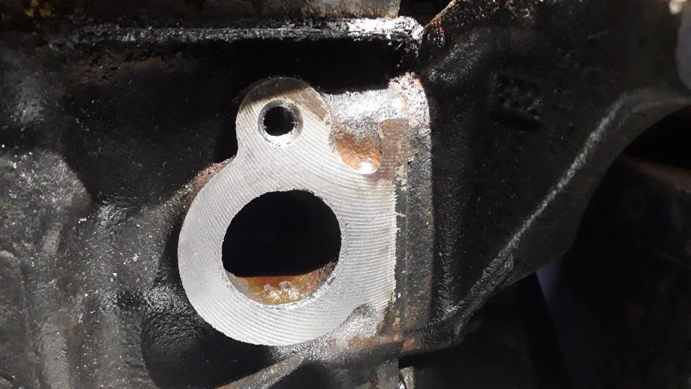
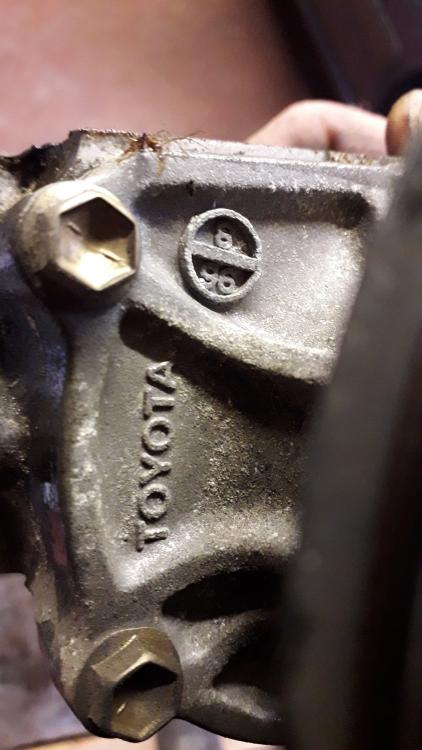
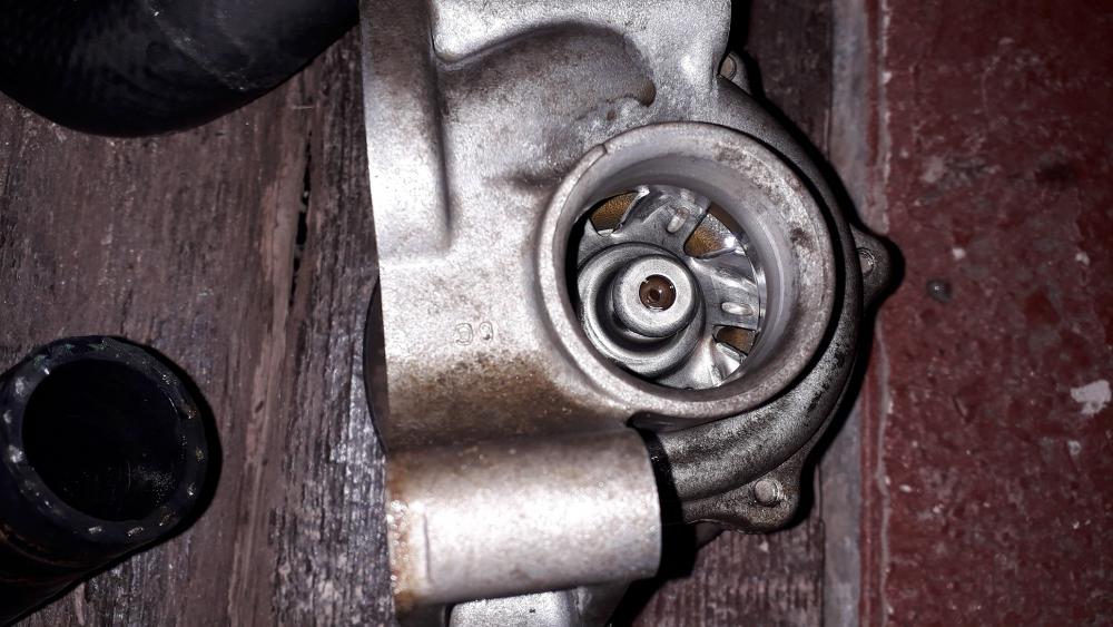
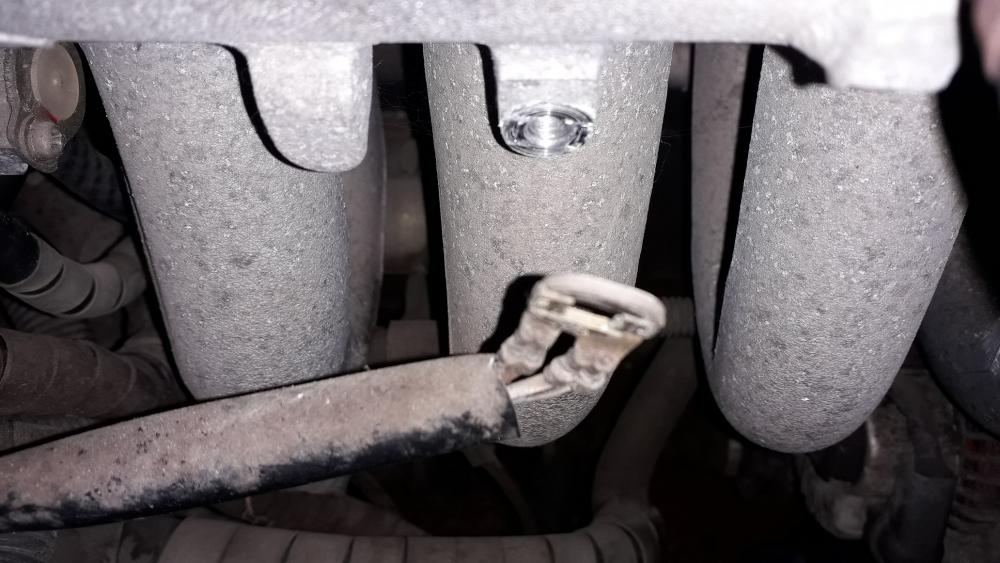
Finally getting somewhere I could actually remove the pump. (12mm socket for 1 x bolt and 2 x nuts). The water tube is held to the block with a single bolt (10mm socket) and I removed this to allow the pump to be separated from the block with the pipe still installed and then I removed the pump from the pipe. Note the metal tab on the pipe locates next to a step in the pump housing to make sure the pipe bracket is correctly angled to bolt to the block on install. At this point I realised I hadn't covered the dipstick / block hole and the torrent of old coolant that had poured from the block on pump removal may have entered the sump a bit! (oh well 😲) Pump off and the O-ring on the tube is clearly visible. I removed it with a small blunt screwdriver ready for the replacement. Cleaned up the block face with a mixture of Stanley scraper to get the worst of the sealant off then a small wire brush to get the remaining material from the machining marks still visible on the face. The pump had the casting date August 96 so looks to be the original one from the Toyota factory. The impeller vanes looked excellent, not rust to speak of. Only a slight squeak when turning which I assumed was the seals. Plenty of life left in it really (only 43k miles on the engine) but peace of mind is an important thing before turboing. Removed the water pipe from its hose to free up its movement and make installing it in the new pump easier. Thankfully the car is as taken apart as it needs to be for this part of the build so next will be the pump install and re-attachment of the ancillaries.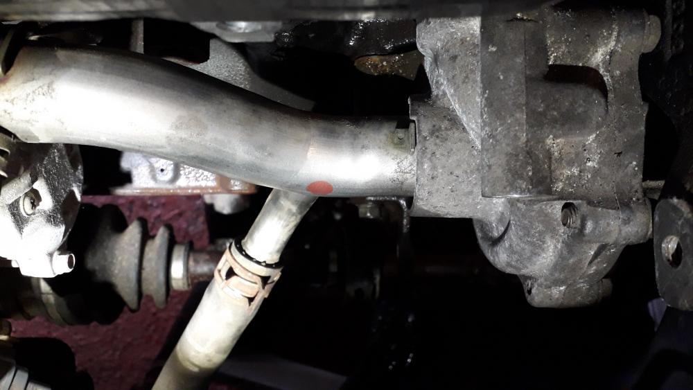
-
Claymore's sleeper 4efe+t-t+t build (R.I.P. the Nanza)
Claymore replied to Claymore's topic in EP91 Progress Blogs
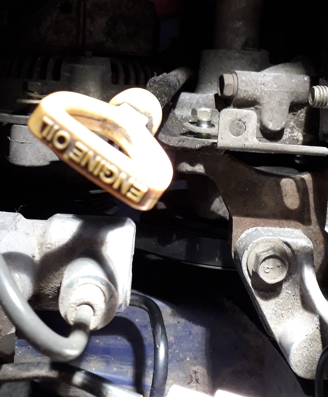
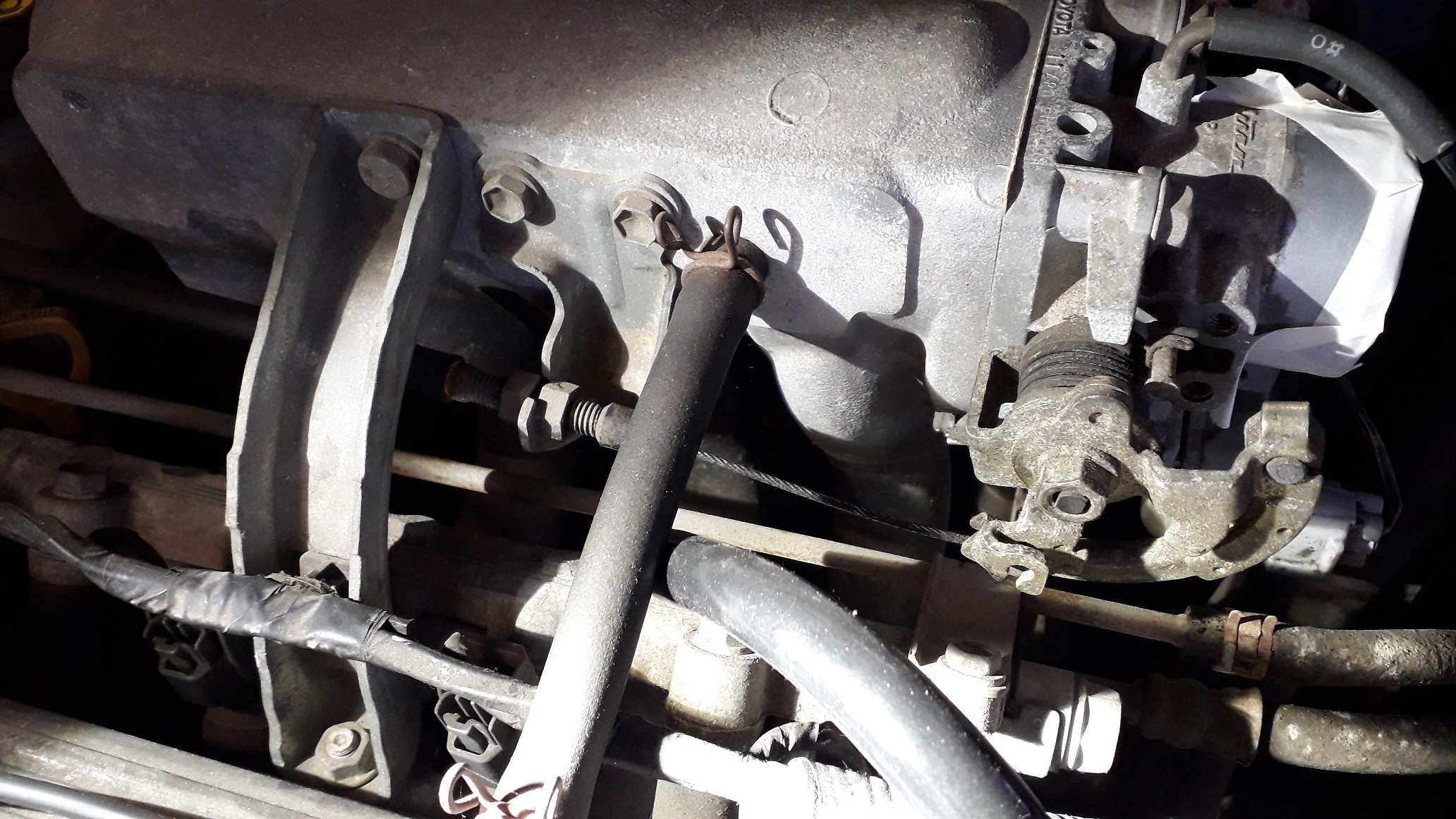
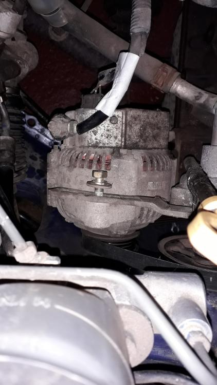
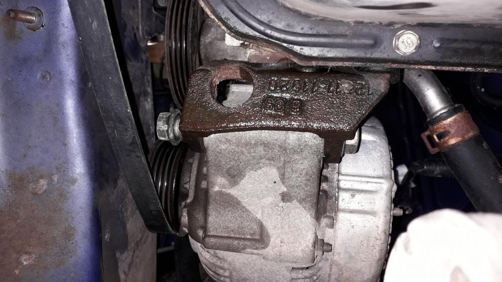
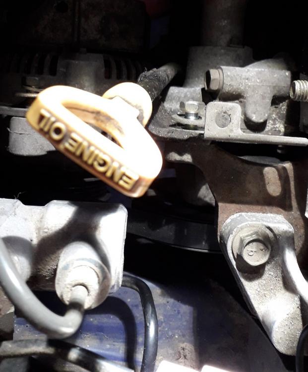
4efe water pump removal. With the manifold off, the alternator was next on the list so I loosened and removed the belt tension adjuster bolt (12mm socket) Disconnected the alternator wiring. (10mm socket and a clip wire connector) Loosened and removed the lower pivot bolt and nut from underneath the car (14mm spanner / socket) Removed the belt tension bracket pivot screw (12mm socket) and the bracket. It also attaches the dipstick tube to the engine mount. Removed the alternator from the engine bay. The dipstick tube was now free so I removed the stick and pulled the tube out of the block. Vacuumed the crust from the hole it revealed in the block.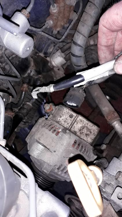
-
Claymore's sleeper 4efe+t-t+t build (R.I.P. the Nanza)
Claymore replied to Claymore's topic in EP91 Progress Blogs
There was a leader board that Socks put together: The link is broken now but it had a lot of dyno graphs (stock n/a to nutty engine swaps) and specs collated and presented very well. Maybe ask him if he can fix the link. -
Claymore's sleeper 4efe+t-t+t build (R.I.P. the Nanza)
Claymore replied to Claymore's topic in EP91 Progress Blogs
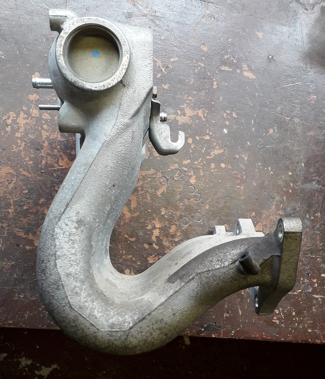
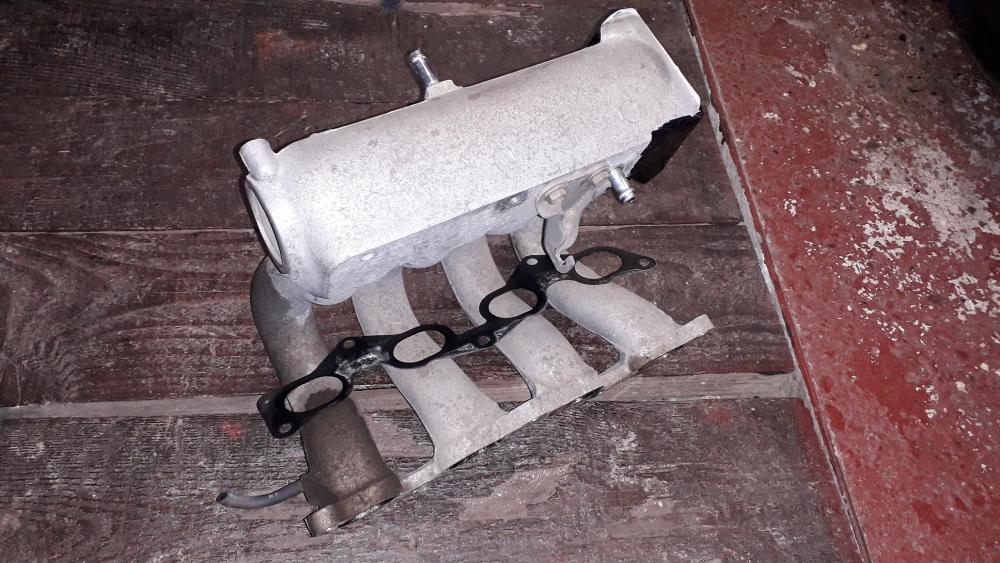
The 4efe stock manifold has quite a tortured path for the air to follow before entering the head, tight bends also.
-
Claymore's sleeper 4efe+t-t+t build (R.I.P. the Nanza)
Claymore replied to Claymore's topic in EP91 Progress Blogs
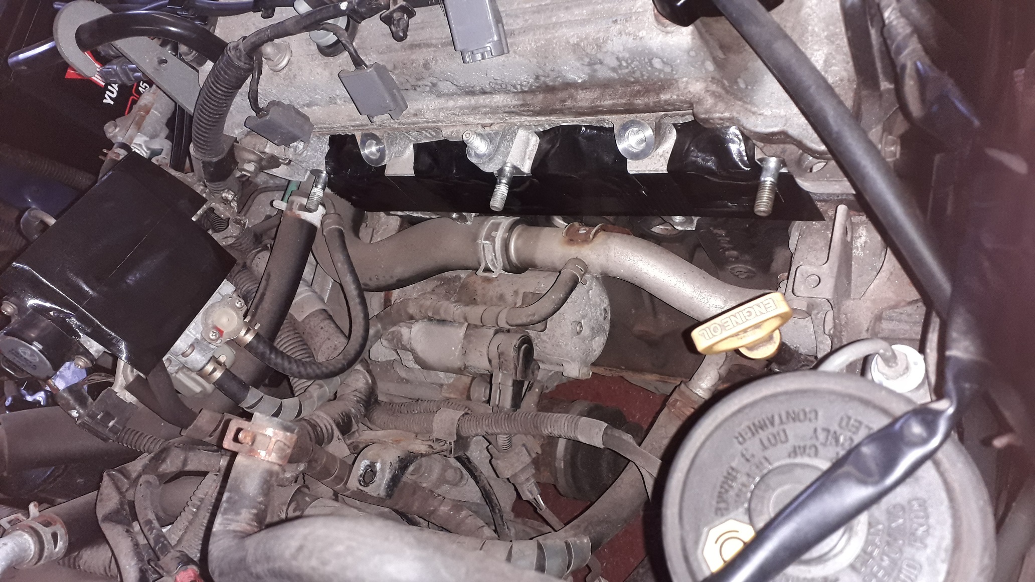
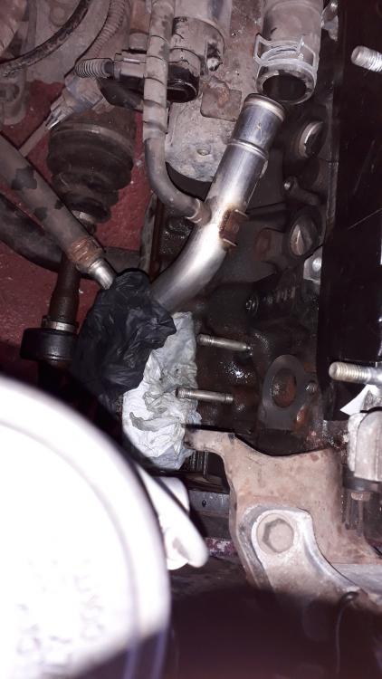
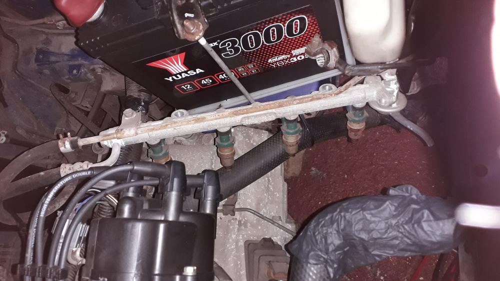
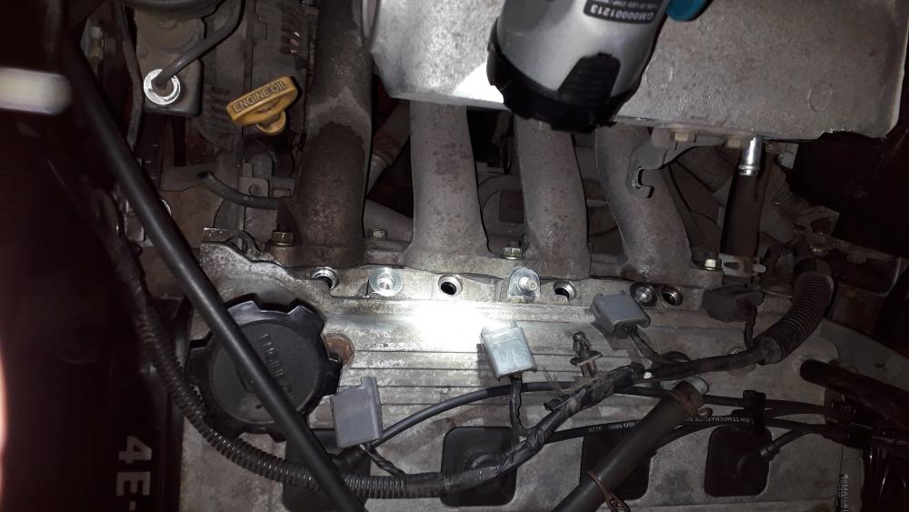
Back in the engine bay..... Unbolted the 4 x bolts that hold the throttle body on and laid it off to the right. Taped up the manifold and back of throttle body. Removed the upper support bracket after unclipping the injector / map sensor / brake fluid level harness from their mounts. Needed to remove the injector rail to gain access to the manifold mounting bolts, removed the 2 x 12mm bolts that hold the rail on, rescued the spacers that fell out and fucked off under the car! The head seals had perished quite badly so I vacuumed up any loose pieces before lifting the rail slowly out. The middle rubber spacers were also munted on a few. Removed the lower injector seals from the head and vacuumed the ports. The 3 x nuts and 2 x bolts could now be removed with the trusty 12mm once again and the manifold was free. Pretty oily inside but finally it was out. Vacuumed out the intake ports and taped up the head to keep it clean. It was also nice to be able to see the water pump (right side in this picture) finally. Still a way to go but atleast the access is improved.

-
Claymore's sleeper 4efe+t-t+t build (R.I.P. the Nanza)
Claymore replied to Claymore's topic in EP91 Progress Blogs
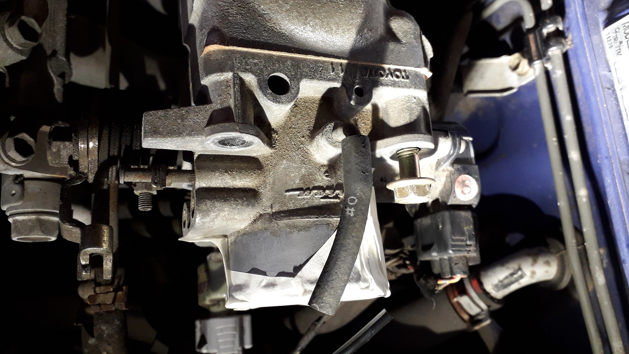
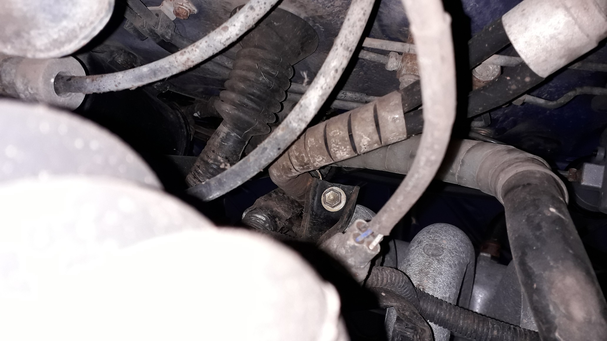
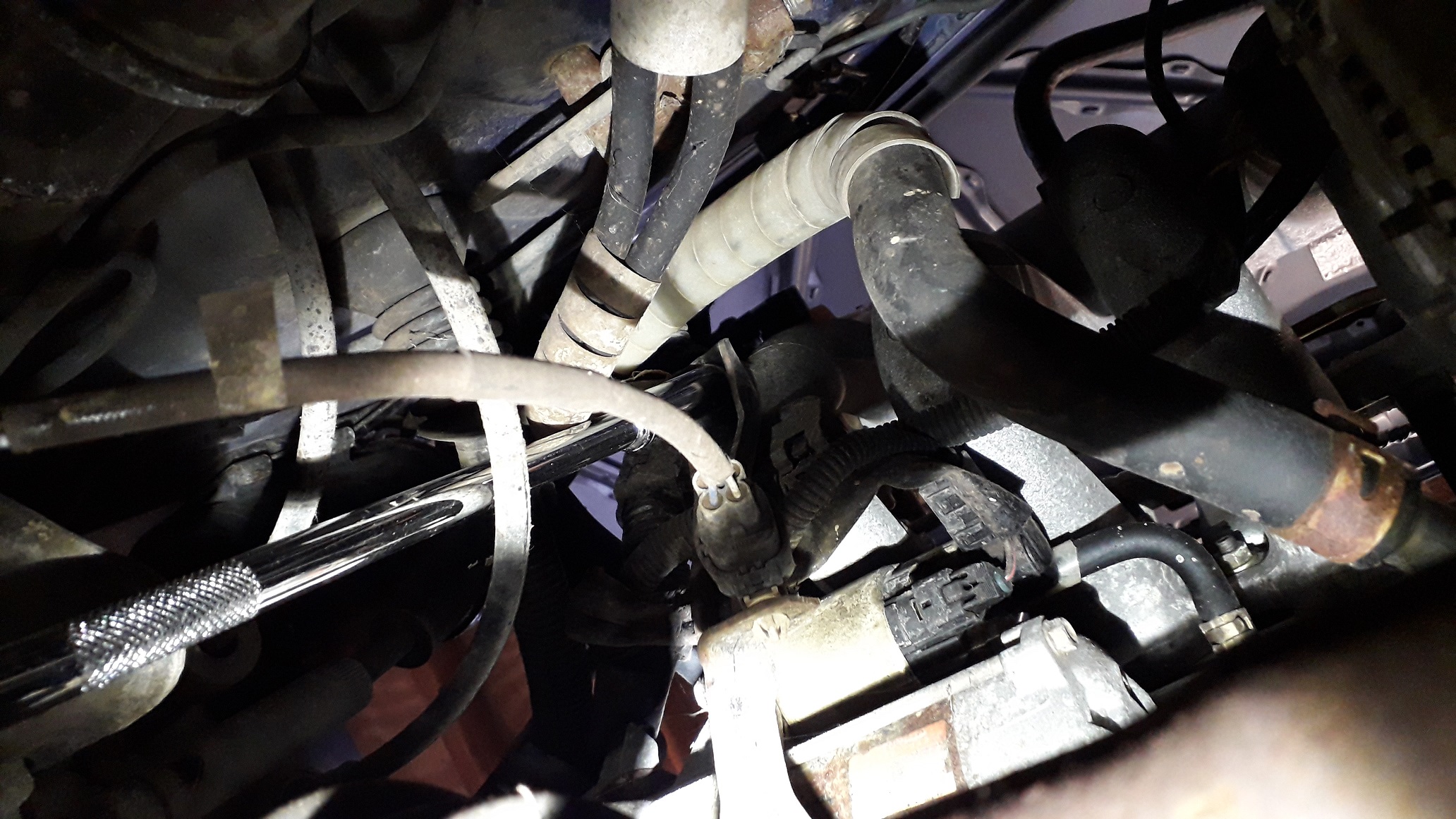
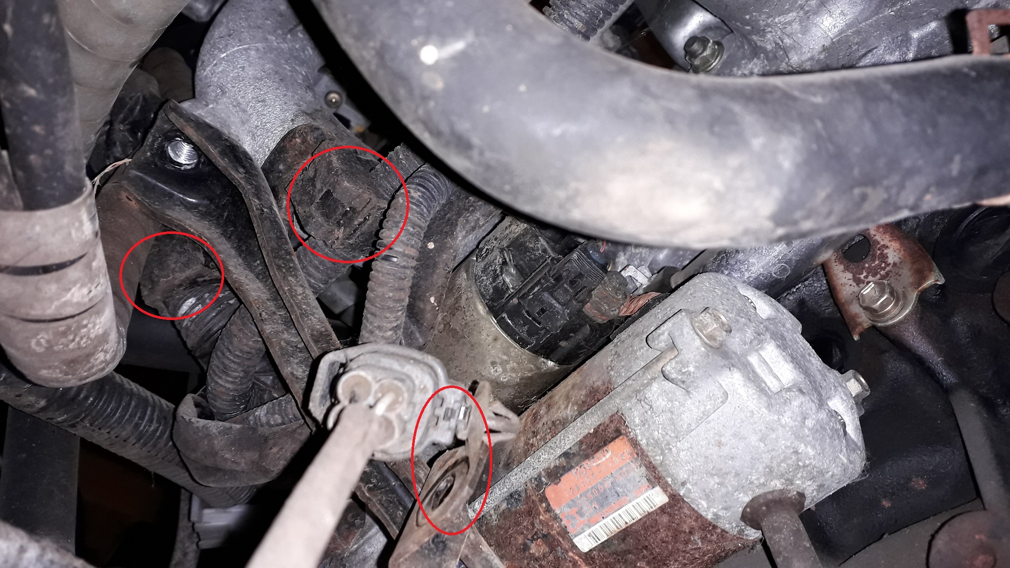
4efe inlet manifold removal. I'm looking to replace the water pump and as the inlet manifold will be replaced with the 4efte version it made sense to do it as part of the pump replacement. So today I started burrowing down the back of the engine to get at the pump. I have a complete water pump with housing so it seemed to be the easiest way of doing it. It quickly became apparent that this is the type of engine bay that requires half the work from above and half from below. So with the car safely on axle stands it was time to start disconnecting things, first I removed the pcv, map sensor, fpr, and tvv hoses from their manifold pipes. Loosened the 12mm nuts holding the throttle cable and unhooked if from the throttle body. Unbolted the 10mm bolt that holds the earth wires to the back of the manifold. Crawled under the car to find the lower support bracket is bolted to the manifold in one place. Used a 12mm long extensions combo to undo said bolt. The lower bracket has the O2 sensor plug, alternator loom and engine wiring loom clipped to it also. The bottom of the bracket is connected to the block with a single nut that I also removed.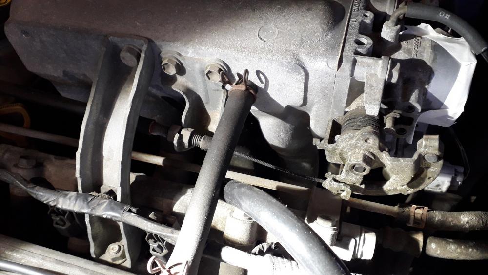


-
Claymore's sleeper 4efe+t-t+t build (R.I.P. the Nanza)
Claymore replied to Claymore's topic in EP91 Progress Blogs
Thanks mate, but always remember this is just a progress blog where I write up my build. If anyone chooses to use the info, it's at their own risk. -
Claymore's sleeper 4efe+t-t+t build (R.I.P. the Nanza)
Claymore replied to Claymore's topic in EP91 Progress Blogs
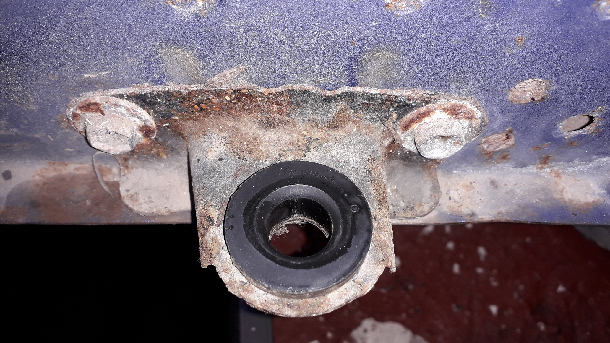
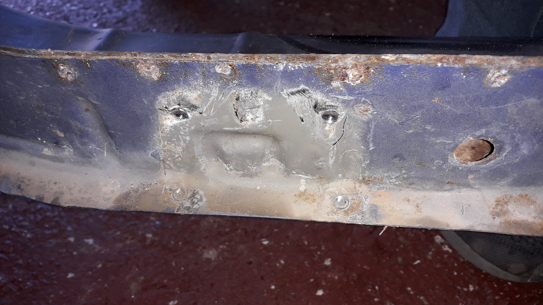
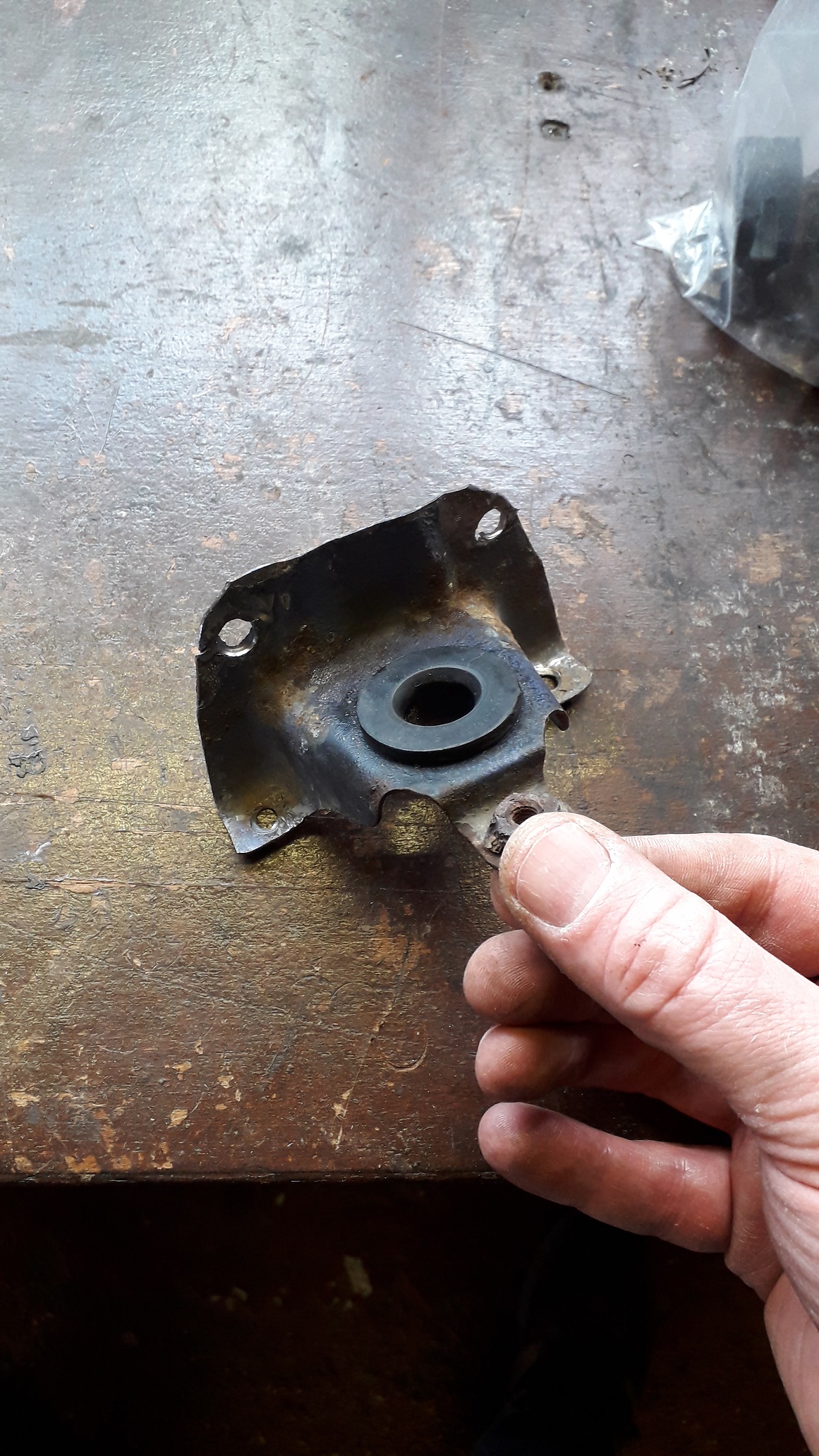
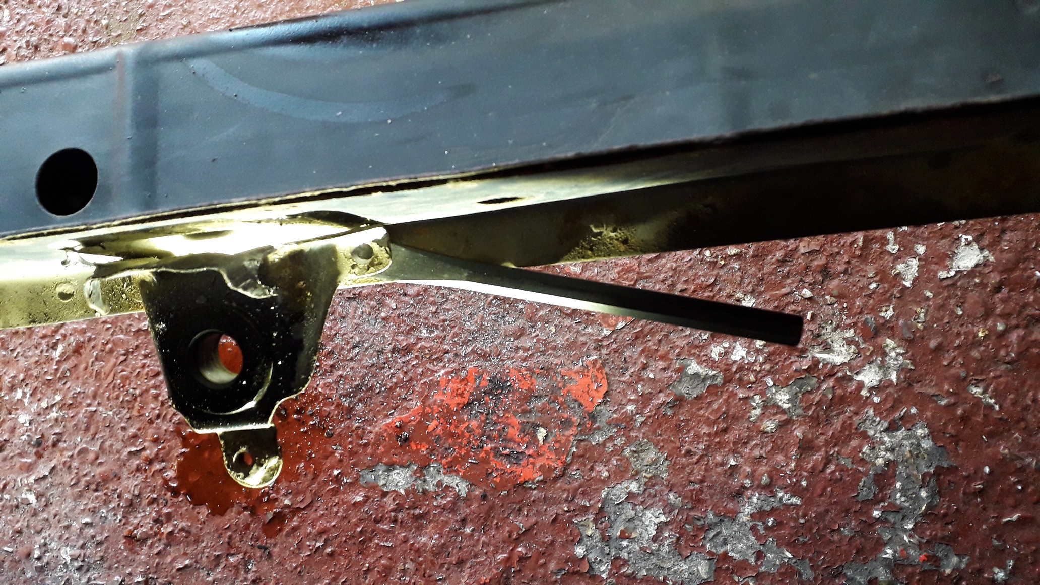
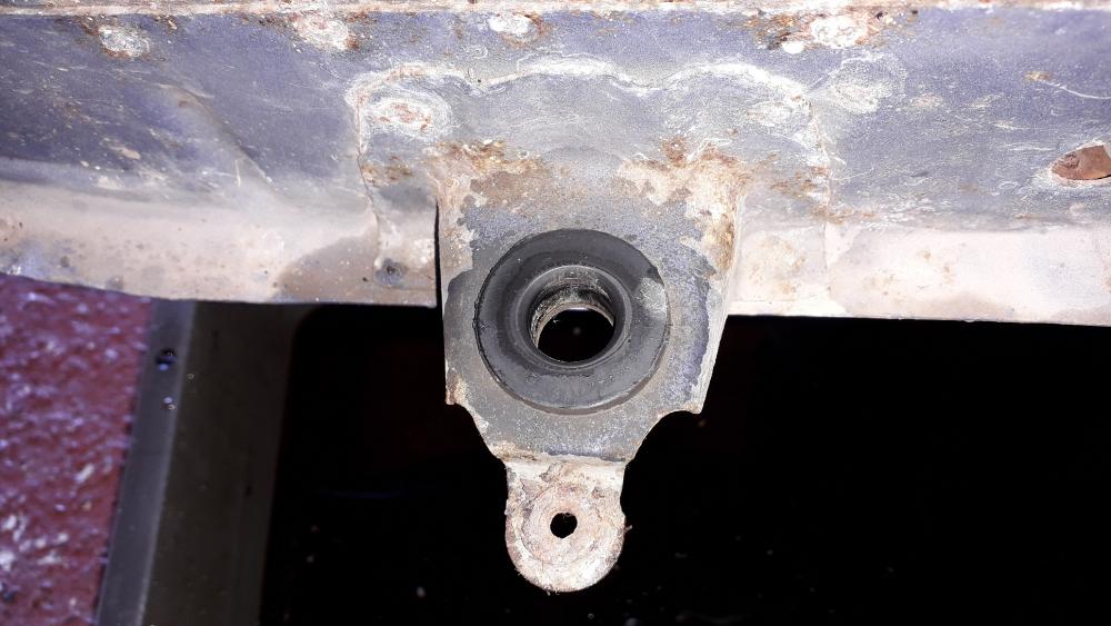
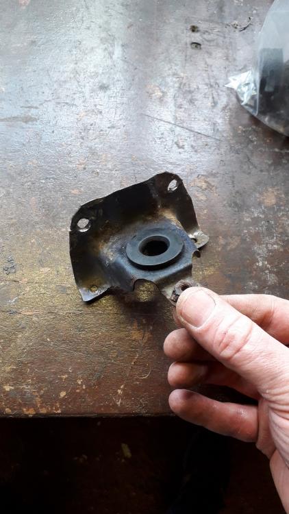
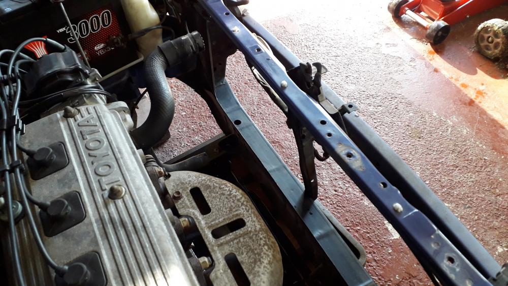
Next the mounting brackets needed to be removed. https://www.youtube.com/watch?v=RpA2T589Y-A The drivers side simply unbolts using a 12mm socket, not really in the way but saves a few grammes of weight I guess. Also leaves a couple of m 8 nut inserts available if required. The passenger side mount is in the way of the replacement radiator and must be removed. It is spot welded to the cross member in 4 places. 2 on the vertical face at the top and 2 on the horizontal lip. I don't have a spot weld drill (never really needed one) so I used and 8mm drill bit to drill part way through the top sheet and spot weld. The spot welds are approx. 5mm diameter and the 8mm bit is a shallow enough angle tip to remove enough material without making a hole right through. With the welds significantly weakened I used a cold chisel and hammer to split the last parts of the welds. Once removed, the remaining welds were dressed back with a sanding wheel on an angle grinder before priming to prevent corrosion. Bracket after removal to show spot weld locations. Also ground back the remaining 2 bolt shafts that snapped when removing the bumper.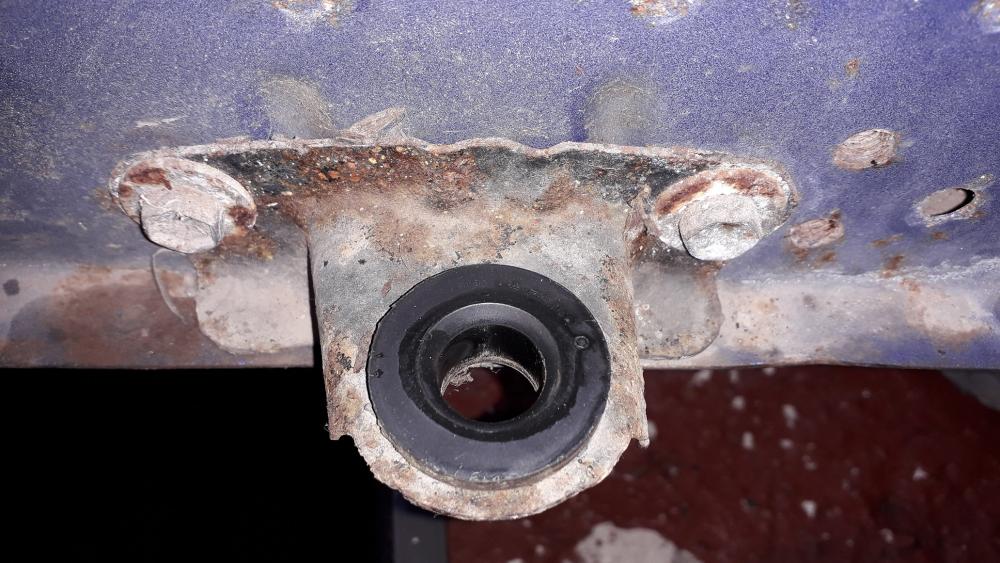


-
Claymore's sleeper 4efe+t-t+t build (R.I.P. the Nanza)
Claymore replied to Claymore's topic in EP91 Progress Blogs
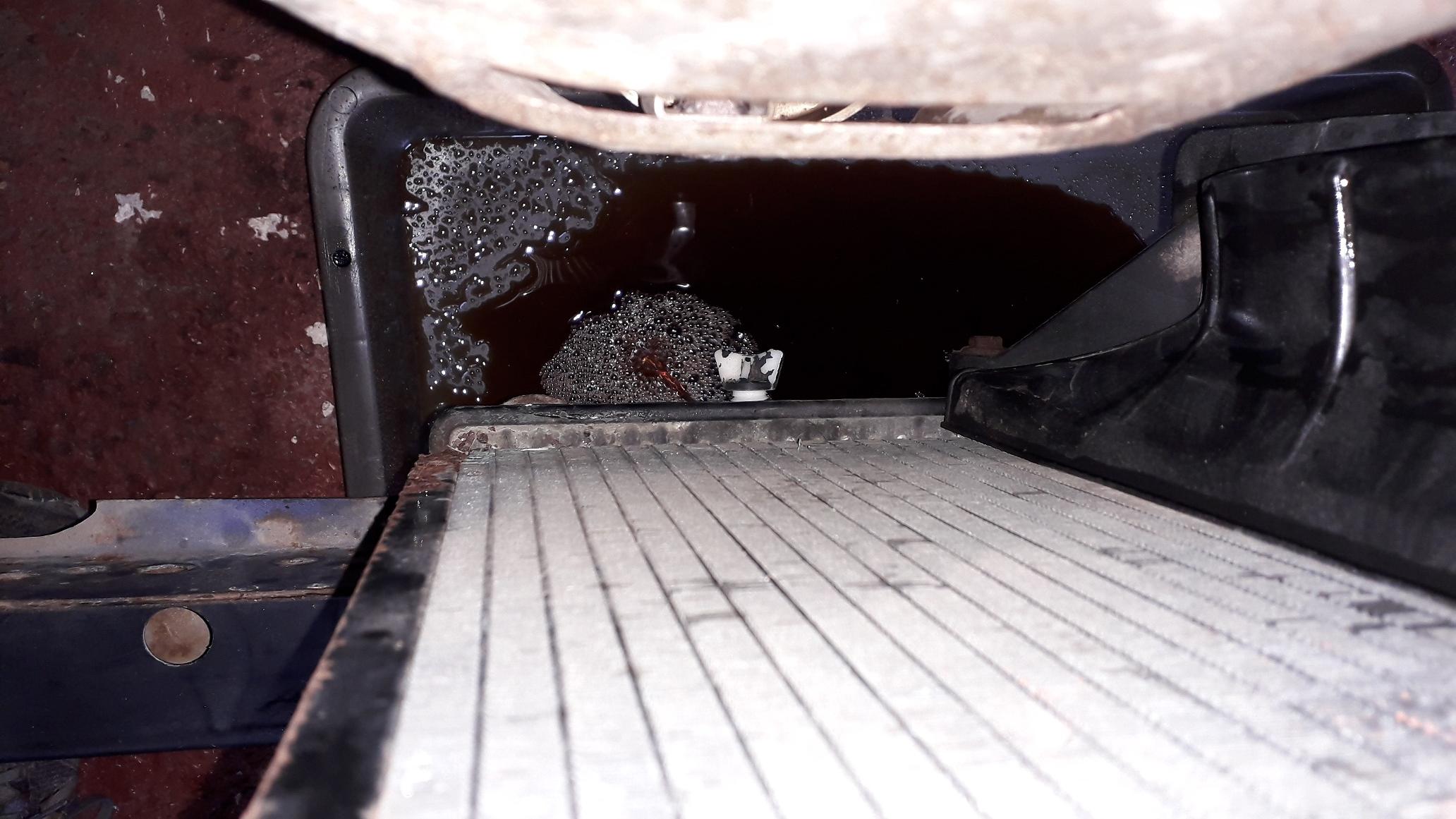
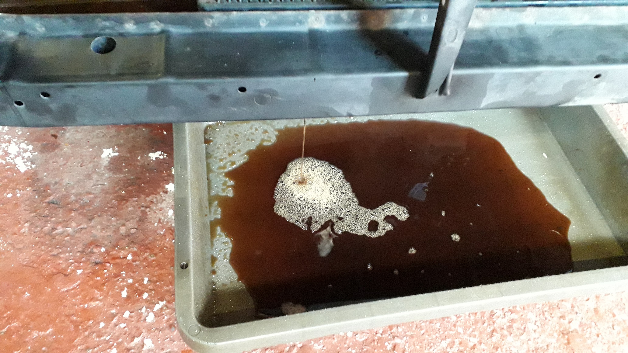
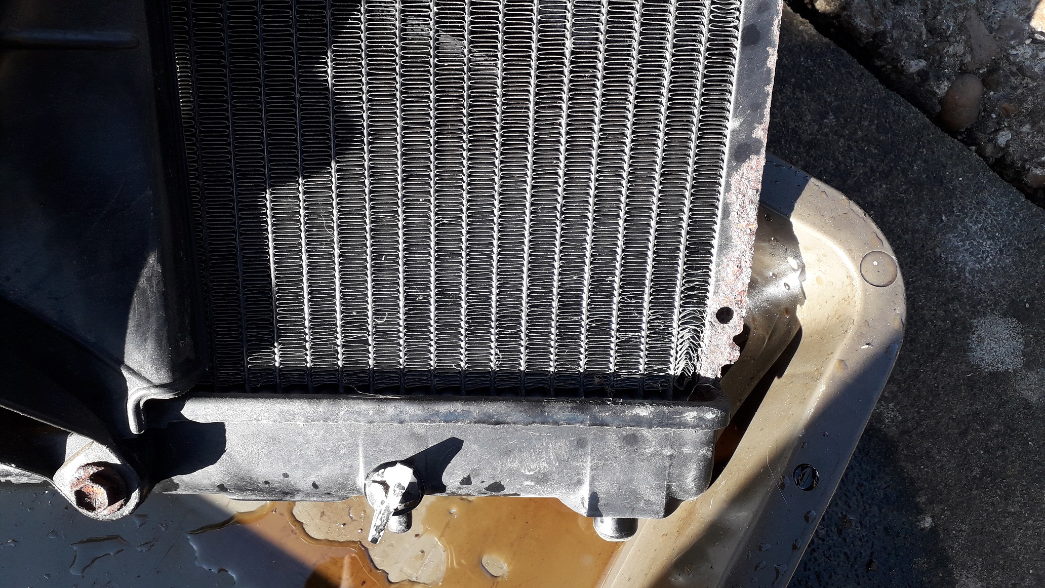
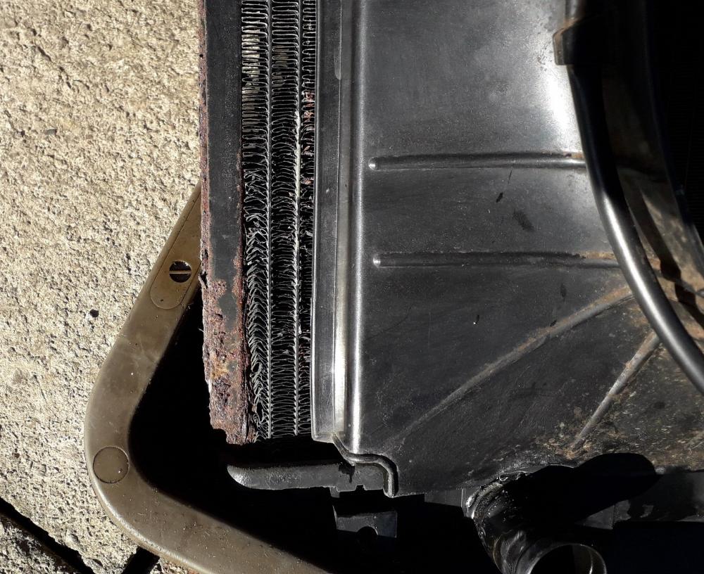
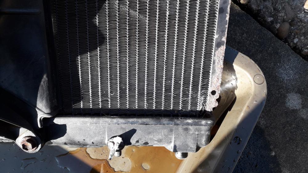
Decided to crack on with cooling system. https://www.youtube.com/watch?v=RpA2T589Y-A Used the petcock on the radiator to drain the coolant (cap off to help speed things up) and disconnected the upper and lower hose once drained. Stout pliers required to squeeze the spring hose clamps open. Coolant was well overdue for a change (5 years my arse!) Unbolted the top 2 clamps with a 10mm ratchet, disconnected the fan electrical plug and carefully lifted out the radiator and fan assembly. The radiator core was badly corroded on both sides and had begun to weep at a small section on the front.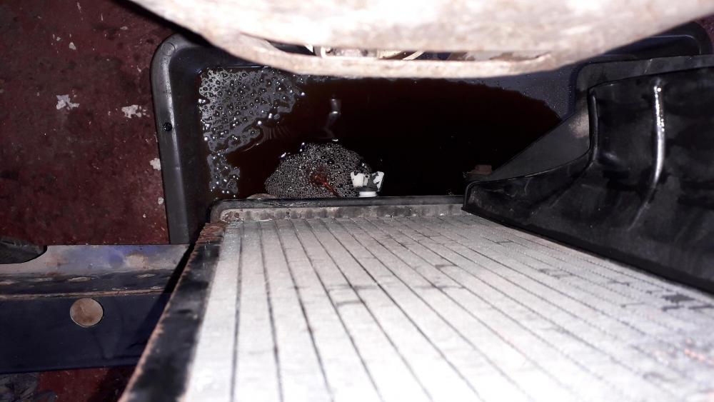

-
Looks great, looking forward to the build.
-
Claymore's sleeper 4efe+t-t+t build (R.I.P. the Nanza)
Claymore replied to Claymore's topic in EP91 Progress Blogs
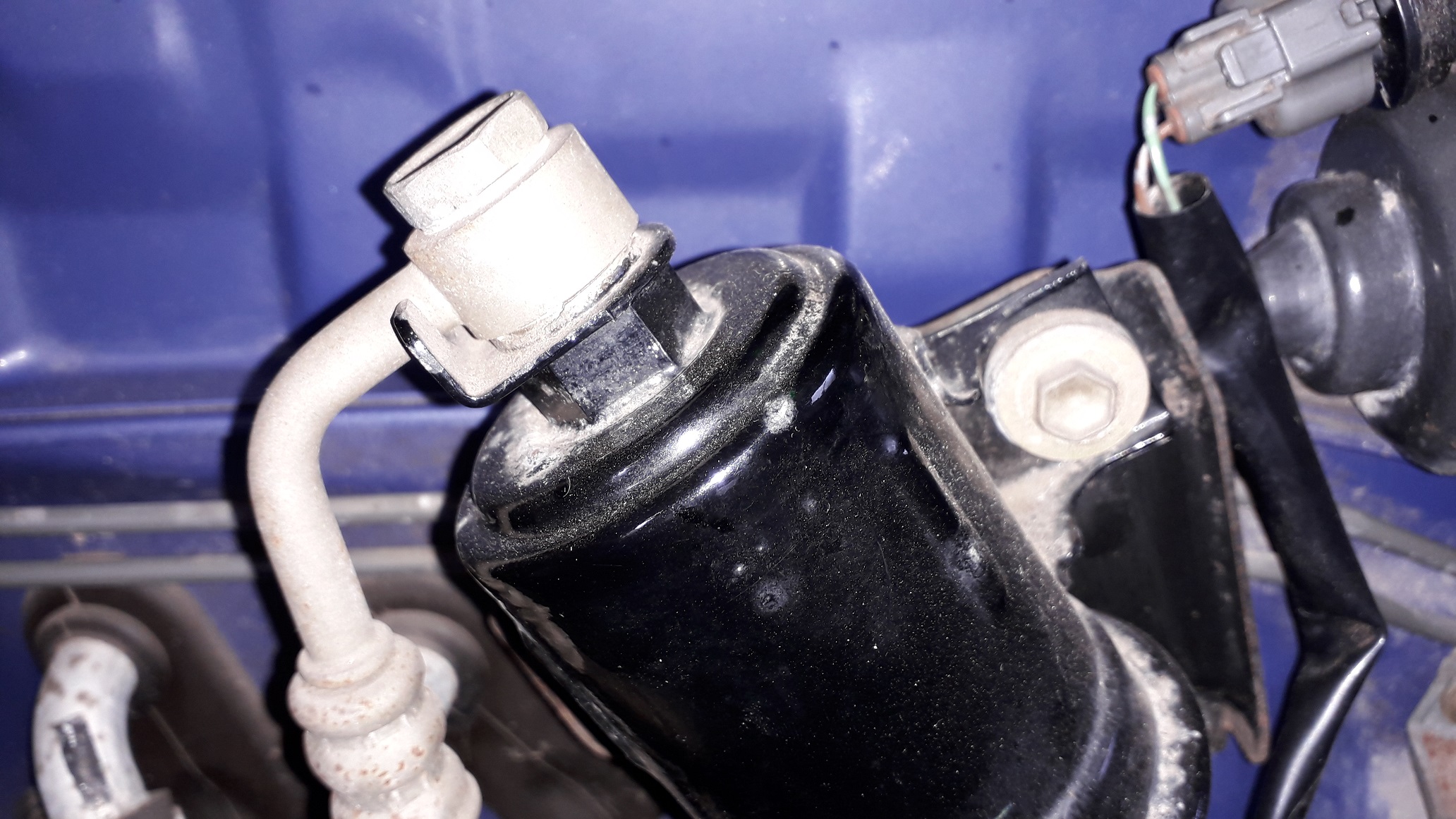
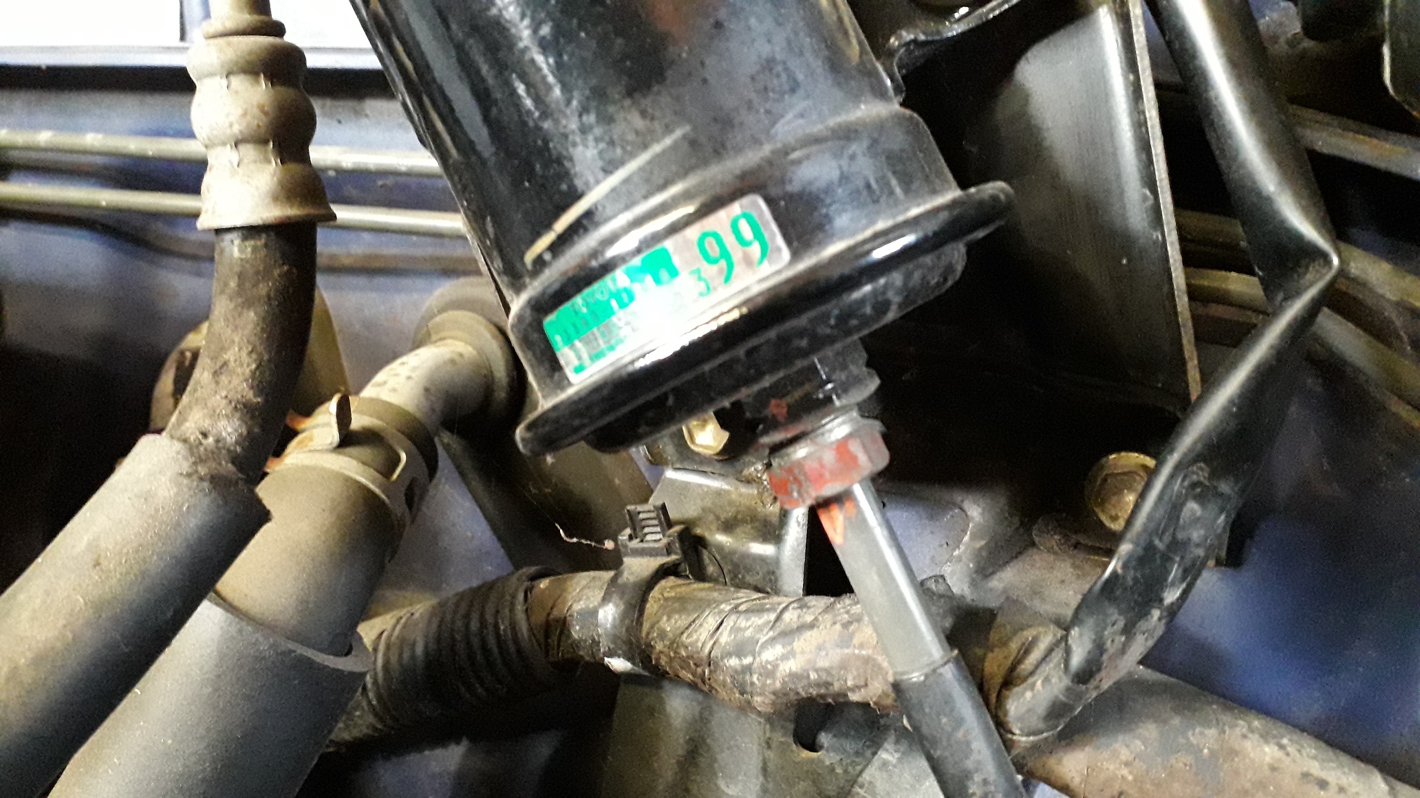
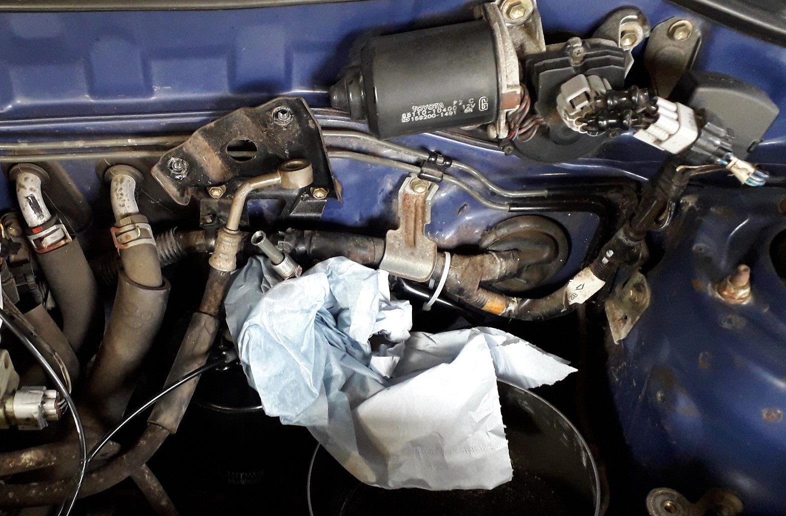
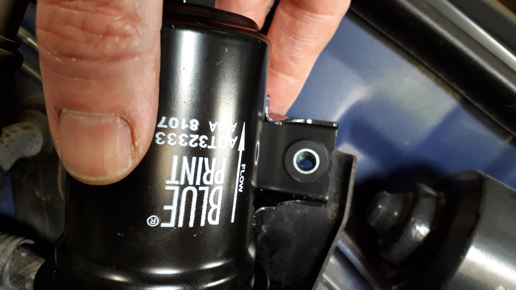
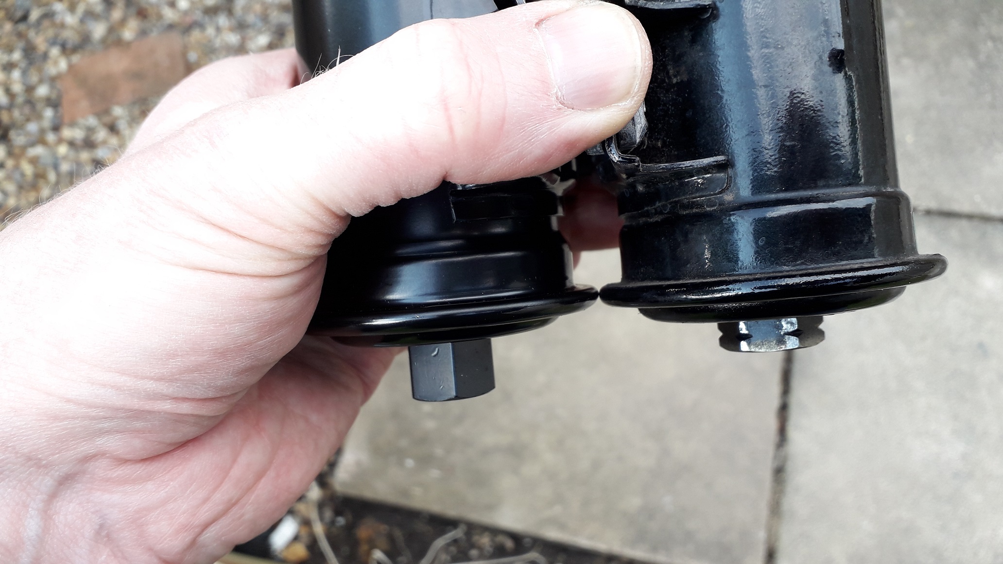
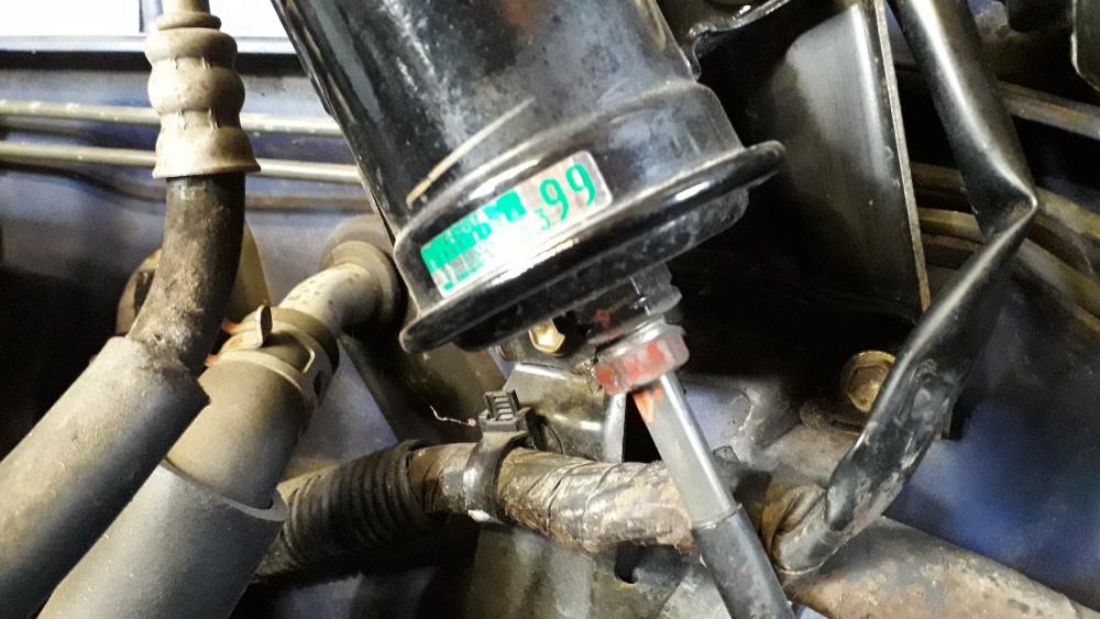
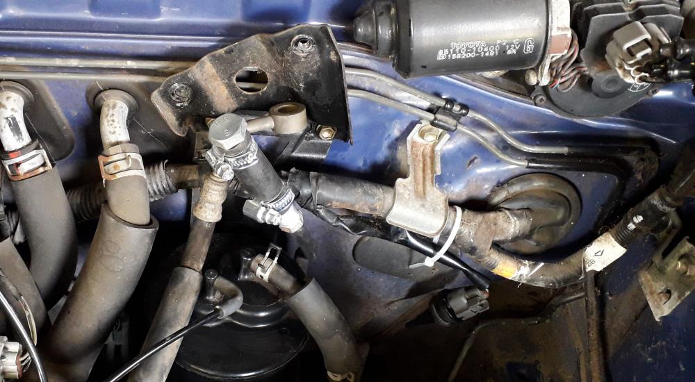
Poxy fucking fuel filter! Part 1. Decided to change the fuel filter as part of the "making things ready for turbo" part of the build. Bought a Blue print ADT 32333 as recommended for the EP91. First up I had to remove the upper and lower airbox and intake pipe for access, thankfully these aren't going back on and are now residing in the "Fuck it bucket". I also removed the Air intake temp. sensor from the upper air box, clipped it back onto the plug and tied it up for safe keeping. The car had sat for a week so the fuel pressure was non existent in the rail. First I undid the banjo bolt from the top hose connection using a spanner and a second on the hex part of the filter below to prevent the filter trying to turn. The lower connection is a flare fitting so I soaked it in wd40 for an hour and again I used the hex above the flare nut to hold the filter steady whilst I undid the flare nut with a brake pipe spanner to prevent rounding it off. It loosened off easily at first but soon became very stiff to turn, thankfully I managed to get it out without damaging anything. Removed the 2 x bolts holding the filter to the firewall bracket and the filter was off. Caught the petrol that came from the filter with rags and pan. Test fitted the filter to the pipe (didn't need to attach the flare nut yet) and it became apparent quite quickly that the filter is different enough to the Toyota item that it wouldn't fit without mods to either the feed pipe (no thanks) or modding the mount bracket. The filter is longer and the mounting holes don't line up with the bracket. 😡 Spot the difference 🤬 Made another contraption to seal the feed pipe temporarily. I have ordered a genuine item from Toyota (only £40) but it wont be here from Japan 'til the end of this month. Cheaper and quicker than Amayama too. Getting pissed off with the poor fit of aftermarket parts, atleast with o.e. parts they'll fit and you know the quality will be better.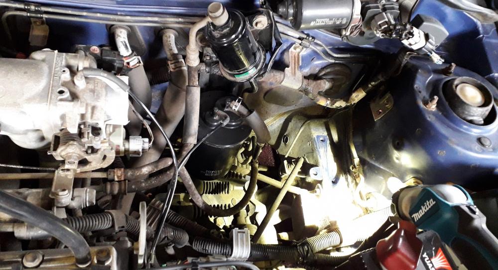


-
Claymore's sleeper 4efe+t-t+t build (R.I.P. the Nanza)
Claymore replied to Claymore's topic in EP91 Progress Blogs
Look forward to seeing the datalogs, are they on your build thread yet? Wouldn't call it aggressive, I'd call it selling a product not as advertised. Might email the manufacturer. -
Claymore's sleeper 4efe+t-t+t build (R.I.P. the Nanza)
Claymore replied to Claymore's topic in EP91 Progress Blogs
I've seen on the det 3 live mapping screen that a sharp press of the throttle can take the cursor close to the 5v end of the table quite easily and quickly with a 1bar map sensor running n/a currently. How repeatably I could do this without a robot leg and some kind of throttle stop I don't know. How do you log fuel pressure (analogue dial in engine bay) vs manifold pressure (electronic sensor) to see the different ratio under vacuum conditions? Sounds like these types of regs suck if that's how they actually behave! 1:1 on boost and totally different in vacuum. . -
Claymore's sleeper 4efe+t-t+t build (R.I.P. the Nanza)
Claymore replied to Claymore's topic in EP91 Progress Blogs
That sounds like something is wrong to me. AFAIK on a 1:1 (linear rate regulator, with vacuum reference) the fuel pressure should rise in line with source pressure i.e. 1psi increase in source pressure = 1psi extra fuel pressure above base setting to counteract. So a base setting of 40 psi becomes 41 psi with 1psi of boost, 42psi with 2psi boost etc. this keeps the actual fuel pressure at the injector nozzle at 40 psi. When you mention rising rate do you mean vacuum reference or a ratio greater than 1:1 such as 1.7:1? For a 1.7:1 (rising rate regulator, with vacuum reference) the fuel pressure should rise 1.7 times that of source pressure i.e. 1psi increase in source pressure = 1.7psi extra fuel pressure above base setting. Trying to nail down the terminology here as I have seen lots of posts with people confusing adjustable fpr with rising rate with vac referenced etc. Technically I suppose all vac referenced fpr's are rising rate (they alter the fuel pressure) but at different ratios. Some manufacturers call 1:1 types fixed rate (linear rise) and 1.7:1 rising rate (a ratio that rises above source) maybe this is the confusion. Did your fuel pressure suddenly increase by 14.7 psi coming off idle or 0psi boost when referenced? Not referenced? At what boost / vac does this sudden increase happen? -
I had a Momo boss on my previous car and from memory it had a horn ring already in it. Maybe there is an accessory from HKB? That's the same oil feed / return I've ordered too! Would have preferred if the oil filter end was a 90 degree fitting to stop the hose from needing to bend but if it works it works. Or if the hose was longer it could be looped round anticlockwise and across.
-
Claymore's sleeper 4efe+t-t+t build (R.I.P. the Nanza)
Claymore replied to Claymore's topic in EP91 Progress Blogs
Went with the Sytec 1:1 adjustable fpr in the end. Couldn't justify the extra cost for the Turbosmart kit I had my eye on initially. Should be more than good enough for my project. Got to be better than those no name, shiny, Chinese eBay things I've seen! -
Claymore's sleeper 4efe+t-t+t build (R.I.P. the Nanza)
Claymore replied to Claymore's topic in EP91 Progress Blogs
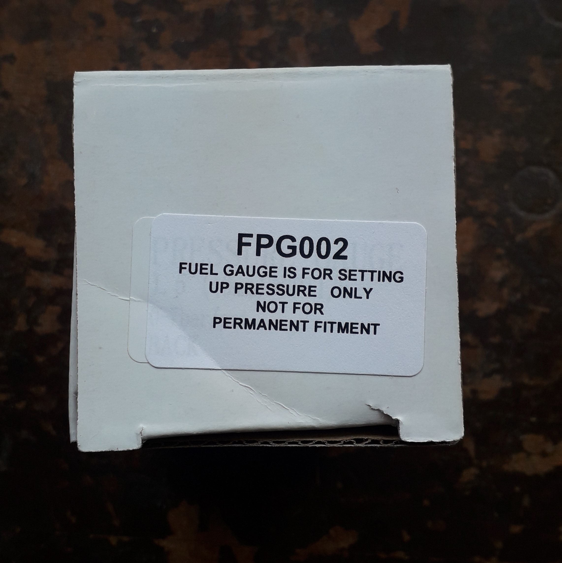
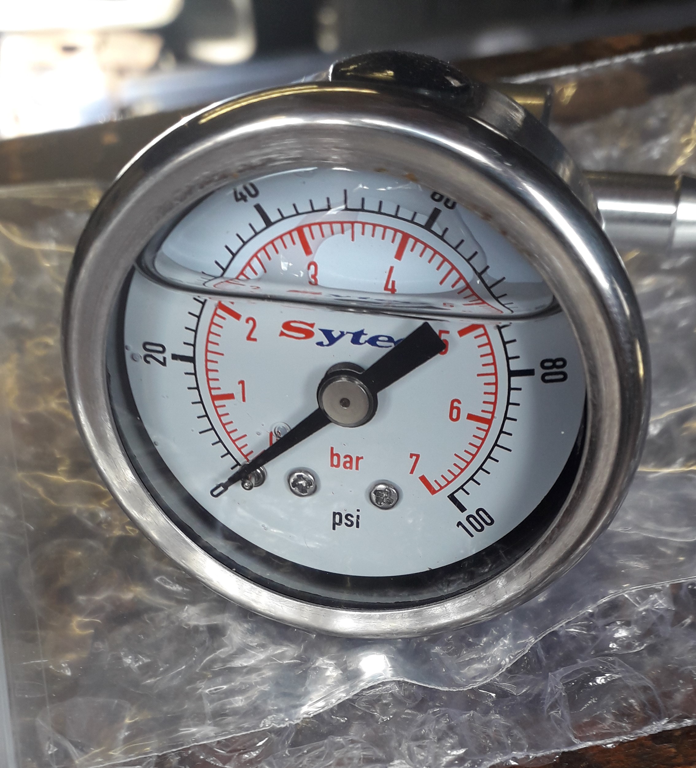
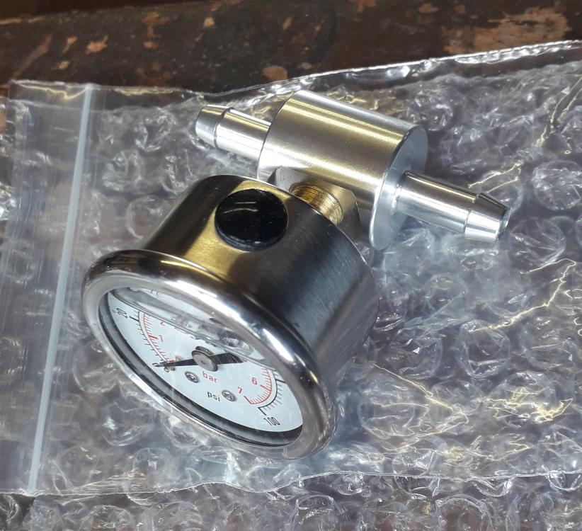
Tiny update, some of the fuel delivery stuff has arrived. The adjustable fuel pressure regulator arrived with the 8mm hose tails and gauge blanking plug already installed with sealer. Didn't fancy disturbing them and as the gauge is not meant to be permanently installed I left it alone and bought an in-line adapter to set the pressure and remove when done. Bought a Sytec gauge and adapter, tapered thread as usual, so lined the bench vice jaws with cardboard and nipped the adapter body in it. Added the loctite 577 to the male thread of the gauge and wound it in hand tight (don't turn the gauge, use the hex part of the body). Used an 11mm spanner to tighten it up the required amount. Got the gauge face to be horizontal to the pipework. Also managed to drill out and re-tap the 2 x m6 bolts I snapped that will hold the undertrays in place. 😀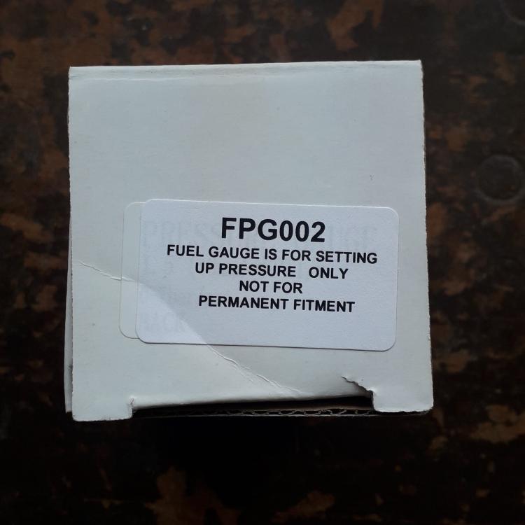

-
Think it depends on your intended hp goals. Costs should be similar to forge either engine. The 5e has the potential for more power (1.5l vs 1.3l) or would make the same hp with less stress on the components. The longer stroke of the 5e should help torque also. If I had the choice and the 4e was capable of the intended bhp goal I'd forge that and sell the 5e as they're very sought after at the moment. If you want big hp or a less stressed engine go 5e. Although I don't think I've heard anyone complain about their forged 5e build on this forum so far!
-
Claymore's sleeper 4efe+t-t+t build (R.I.P. the Nanza)
Claymore replied to Claymore's topic in EP91 Progress Blogs
Thanks Sam Cheers mate, between me, you and JamesG I think we have the CT9 rebuild content covered recently! -
Claymore's sleeper 4efe+t-t+t build (R.I.P. the Nanza)
Claymore replied to Claymore's topic in EP91 Progress Blogs
Thanks mate. You can get lucky sometimes with the reverse drill bits, I've found them useful for m 8 sizes and up. Smaller than that and I haven't had much luck, nothing worse than snapping a tiny "easy out" extractor off in one either! Hopefully not too quick spool! Thanks for the kind words, I'm getting there. -
Claymore's sleeper 4efe+t-t+t build (R.I.P. the Nanza)
Claymore replied to Claymore's topic in EP91 Progress Blogs
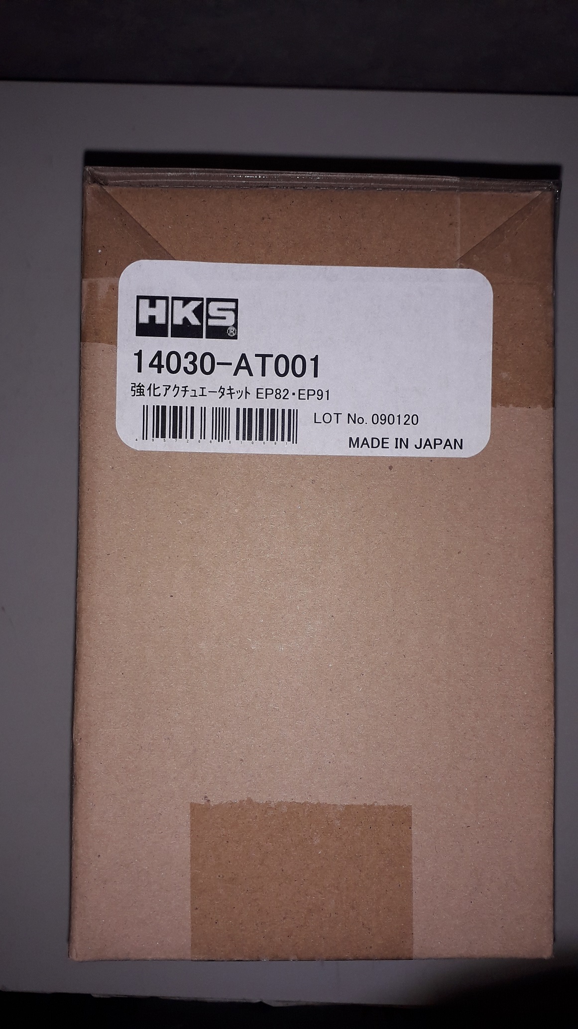
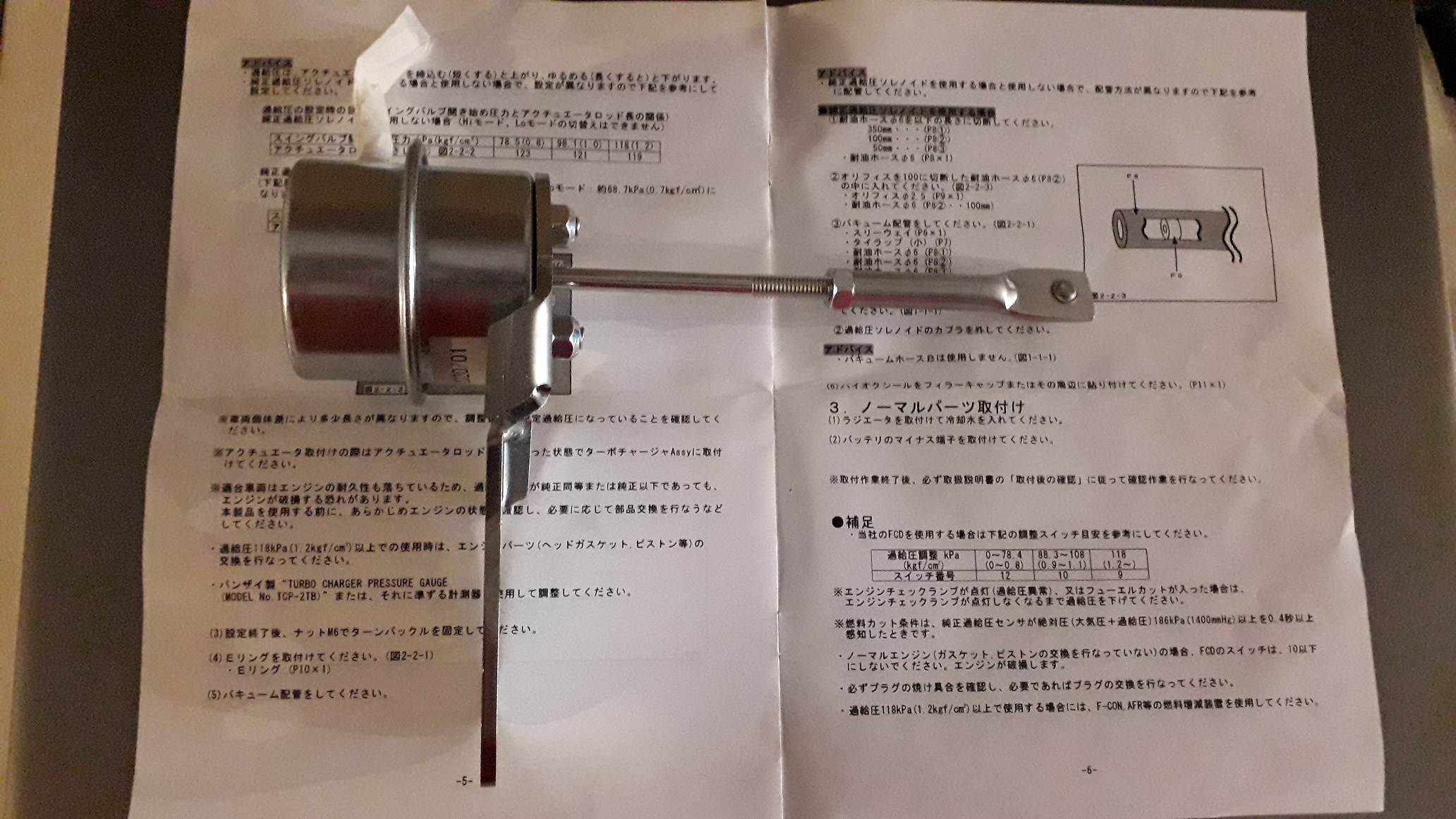
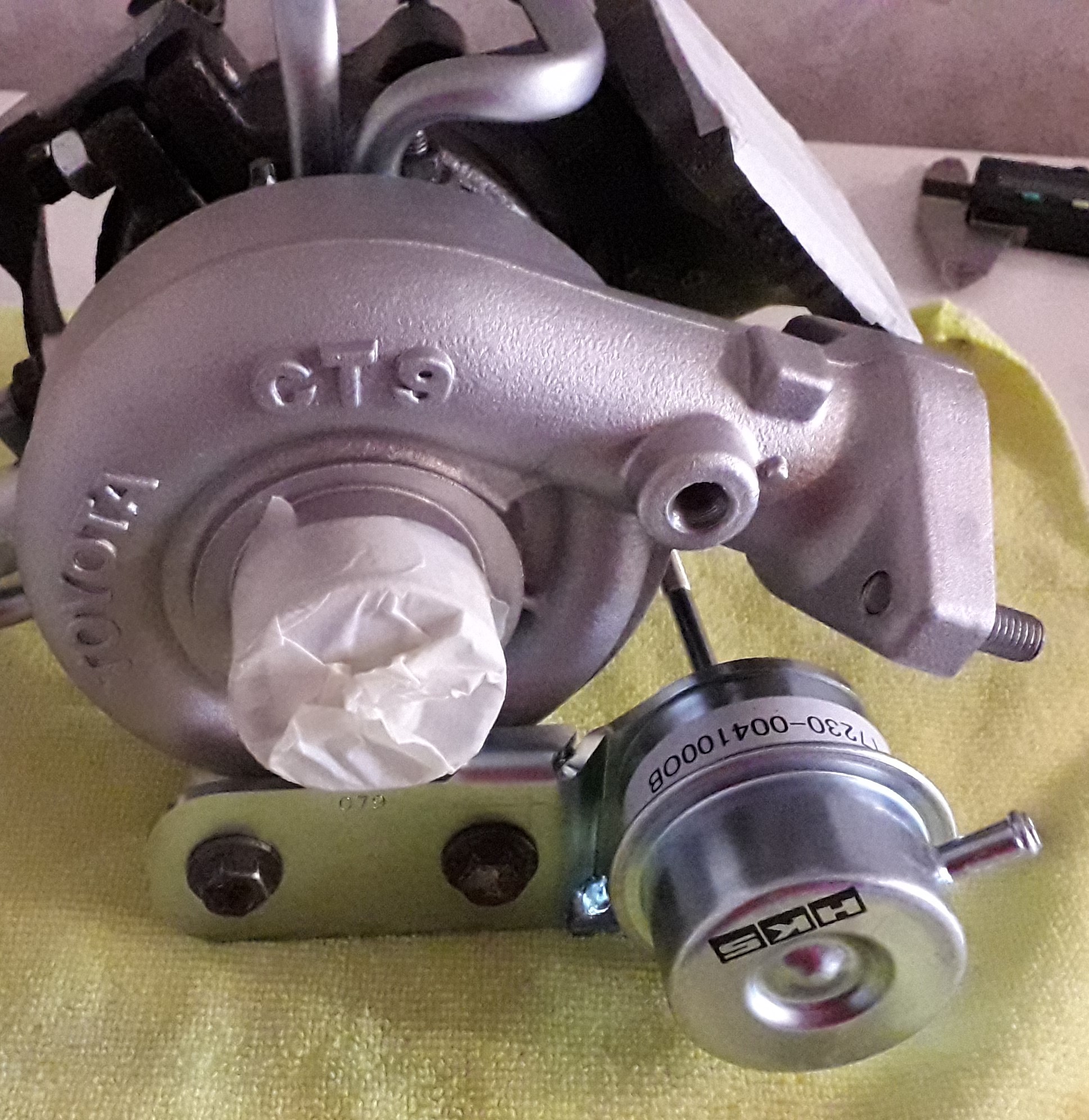
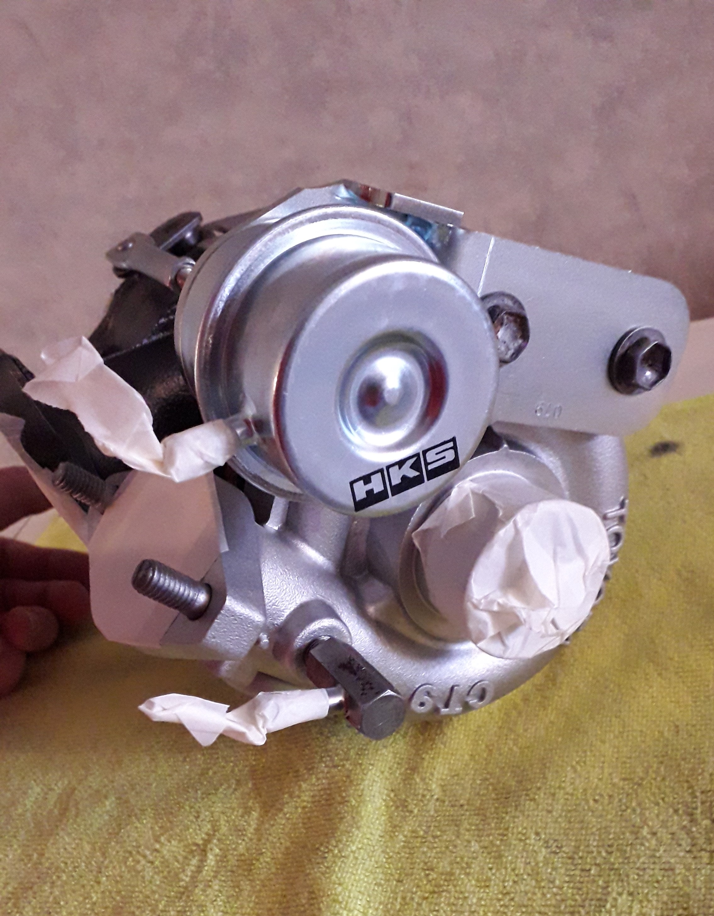
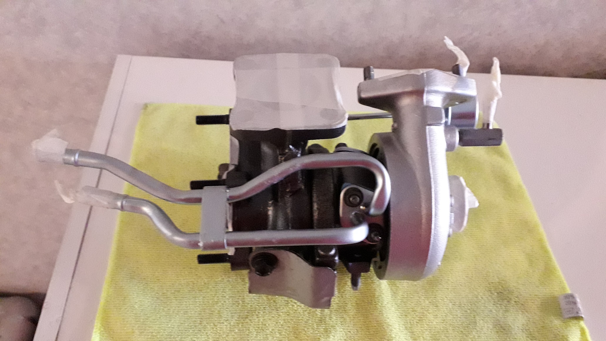
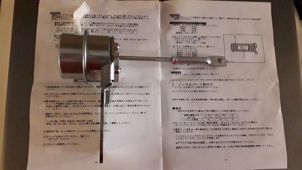
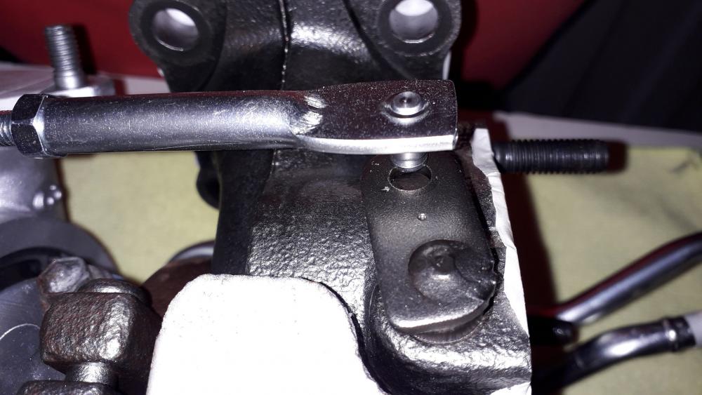
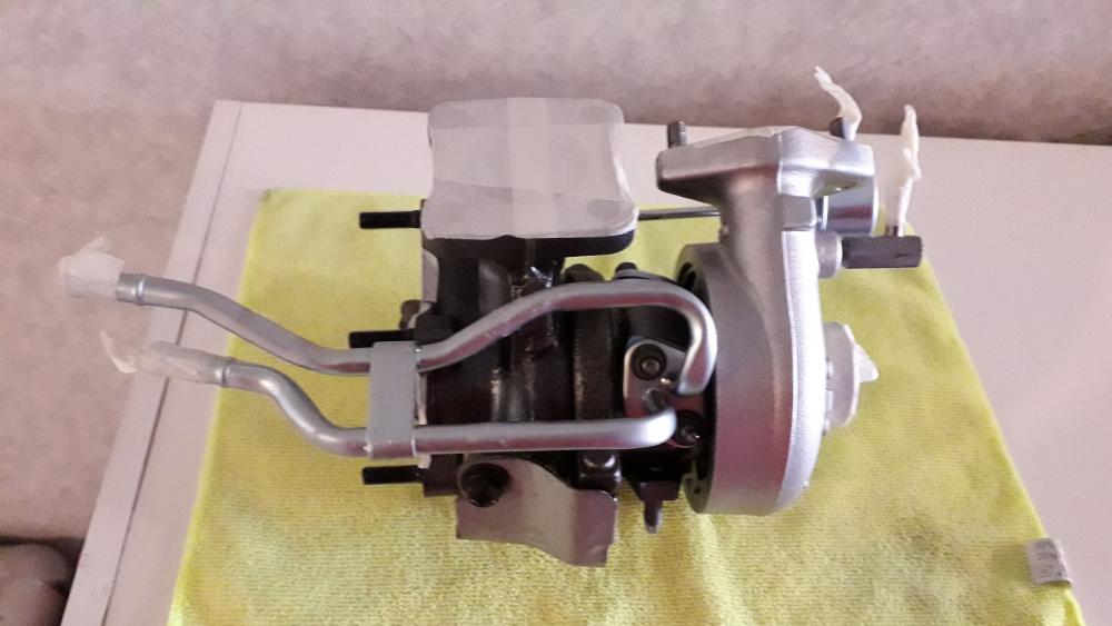
Turbo assembly. After getting the CT9A back from Midland turbos I thought I'd get a head start building it up, I got the water pipes, blanking plate and oil feed / drain pipes re-plated (BZP, 7 microns, clear passivate.). Also bought a HKS actuator to replace the tired looking original 2 port jobby. Easy enough to assemble, the bracket is attached to the actuator so the turbo housing mounting face is to the left of the actuator mounting face (as shown below). If you put it on backwards you'll get all the psi's! The actuator rod is adjustable for length via a turn buckle end and lock nut, after choosing the appropriate end (hole for bolt or axle with e-clip) to suit the turbo. The turnbuckle was also pre-greased with copper grease (now this I like!). Used google translate to help decipher the instruction manual (scan setting works alot better than live translate 😉). Length settings and approx. boost: 119mm (1.2bar), 121mm (1.0bar), 123mm (0.8bar) and 128mm (0.5bar). The shorter the length, the more preload on the spring resulting in an increase in pressure required to actuate the wastegate. Set the arm length at 128mm (0.5bar) as this is all I'll need for the N/A+T. It's also the lowest setting so be aware of that if you want less boost. After attaching the actuator to the compressor housing (2 x m 8 bolts) it became apparent that when the turbo was rebuilt the boost source fitting had been tightened in (taper thread) further. This meant that the nozzle pointed at the actuator and I couldn't get a hose on it. Removed the fitting, cleaned it out and reassembled with thread seal at the correct angle. Pulled the actuator rod into the wastegate lever hole. At the 128mm setting it barely adds 0.5mm of preload. Will adjust tighter if necessary. I was quite surprised how much stronger the spring was than the standard item. I assume this is to do with the 2 mode turbo settings on the stock glanza actuator. Bolted the water pipes and blanking plate on (2 x m6 nuts or bolts). The turbo came back with a gasket set to re-assemble so they were used where required. Made sure all openings were taped up. Finally, I added the original small heat shield to the turbine housing (2 x m 8 bolts again). I have ordered a new, aftermarket oil feed / return which will be fitted when it arrives.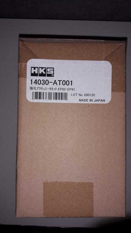


-
Claymore's sleeper 4efe+t-t+t build (R.I.P. the Nanza)
Claymore replied to Claymore's topic in EP91 Progress Blogs
Bargain She'll be worth the wait mate, the celica resto photos looked excellent.