Claymore
-
Posts
660 -
Joined
-
Last visited
Content Type
Profiles
Forums
Wiki
Media Demo
Events
Everything posted by Claymore
-
Thanks mate (I've replied to the PM, hope you got it), I'll check them out. 👍
-
Hey Dutchie, Can't PM you still. I saw on the other site you were talking about building a plug n play ecu. Do you know where you can buy the Toyota ECU socket from? Also looking for the plugs with pins from the car wiring loom to match. Tried my local Toyota and they said would have to buy a complete loom! 🤪 Must be somewhere online that does them for homebrew pnp.
-
Claymore's sleeper 4efe+t-t+t build (R.I.P. the Nanza)
Claymore replied to Claymore's topic in EP91 Progress Blogs
Thanks mate The whiteline products are good on the whole but the instructions are vague at best and non existent in the case of the panhard rod. If it helps prevent other people having problems it's all worth the effort to write up my experiences. -
Was watching this during the week: https://www.ebay.co.uk/itm/toyota-starlet-EP91-tubular-inlet-manifold-4E-FE-engine/133562326872?hash=item1f18ef5f58:g:xJwAAOSwEK5fnY9p&autorefresh=true £185 for a manifold that used to sell for £50 ! Rare items on the up.
-
Had a quick search and came up with these threads that had photos re. ac bridging: Some say its a 2 wire plug others say its a 4 wire? Should be located passenger side behind the battery area originally attached to a sensor in a pipe. Yours might have the sensor plugged in then taped up in the bundle behind the battery, or you might be able to compare the wire colours of the plugs to the photos on the threads above.
-
Claymore's sleeper 4efe+t-t+t build (R.I.P. the Nanza)
Claymore replied to Claymore's topic in EP91 Progress Blogs
Thanks mate 👍 -
Claymore's sleeper 4efe+t-t+t build (R.I.P. the Nanza)
Claymore replied to Claymore's topic in EP91 Progress Blogs
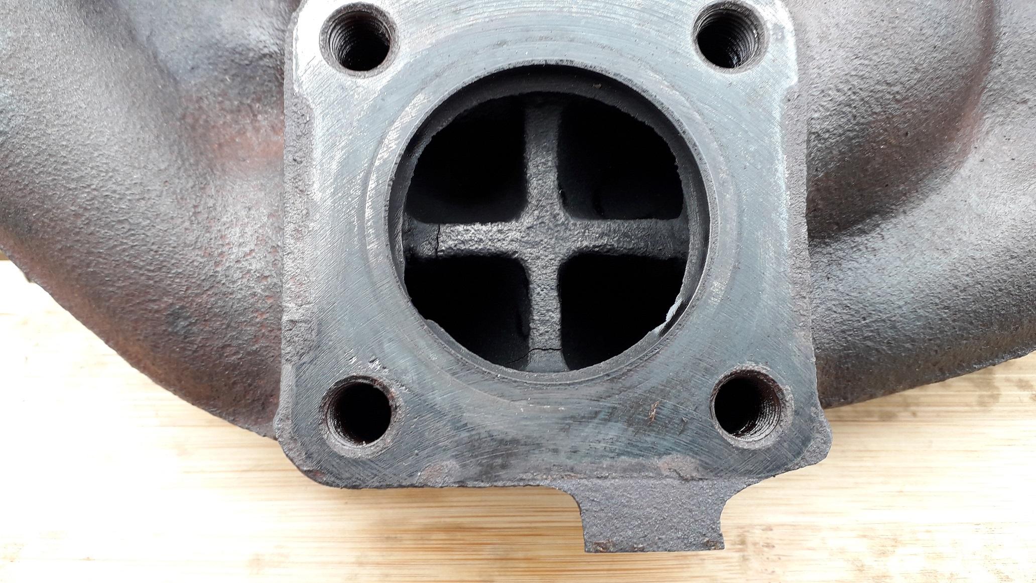
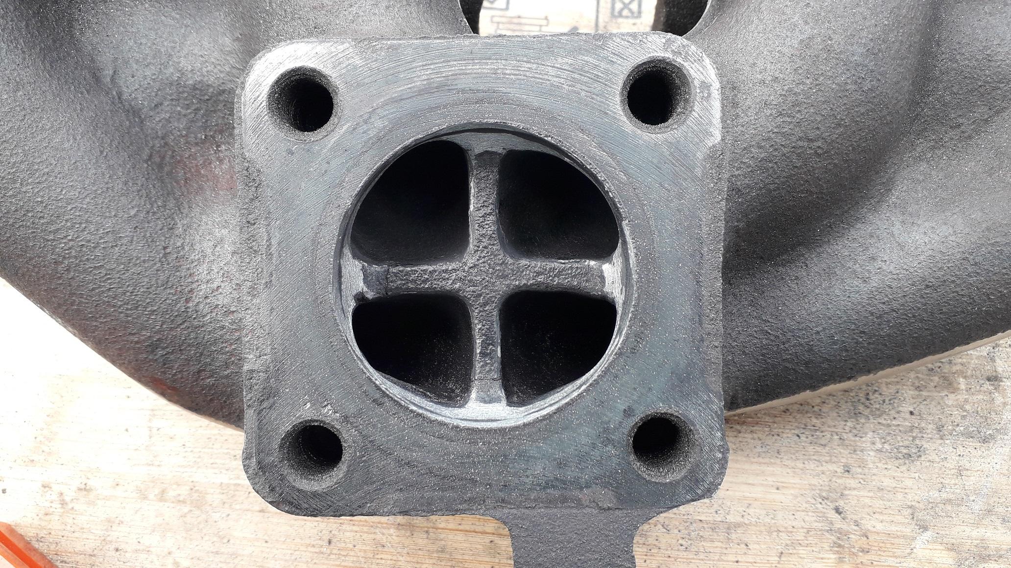
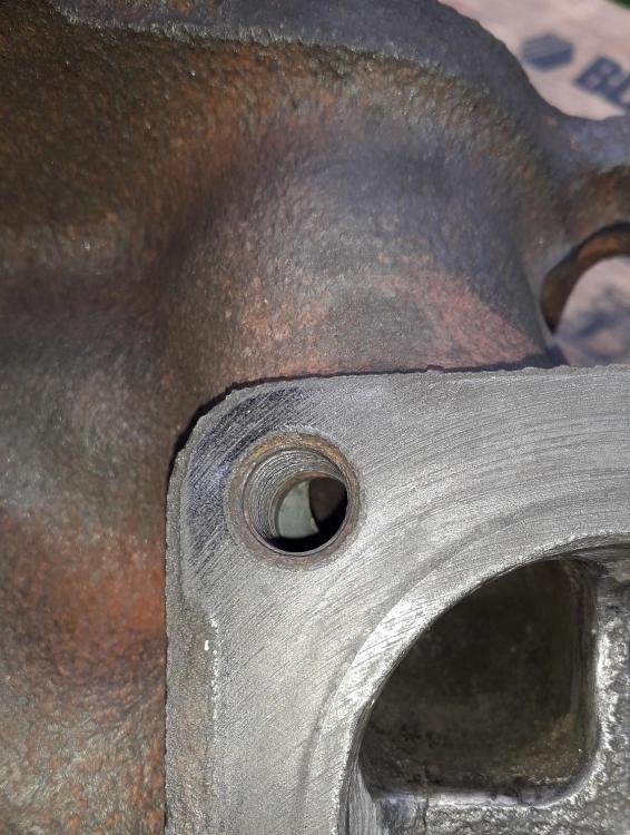
Turbo flange side after, grinding and sanding. Much more balanced for port size. Decided to leave the cross in, I know some people used to remove them for max. flow but not required on this build so I left it in for strength and to help prevent the exhaust pulses firing down the opposing runner. Rounded off the sharp edges of the cross to remove stress risers and try and prevent new cracking. Generally smoothed out inside runner exits to help flow. No.3 runner restriction removed. When removing the lump from runner 2 it always breaks through into the bottom of the threaded stud hole. Not very much though and the stud can be sealed in to prevent leakage which once tightened should be minimal anyway. Same for runner 3 but to a slightly larger amount. All in all pleased with the result. Once you start looking at the stock manifold it is quite easy to see where the work needs to be done. The Carbide burr was like a knife through butter and the whole process took about 3 hours max. and I was taking it slow to prevent mistakes. Using a grinding stone would have taken days. Just need to sand blast it and paint VHT black when we're allowed out to play again. Might also look at refinishing the mating surfaces of the flanges too.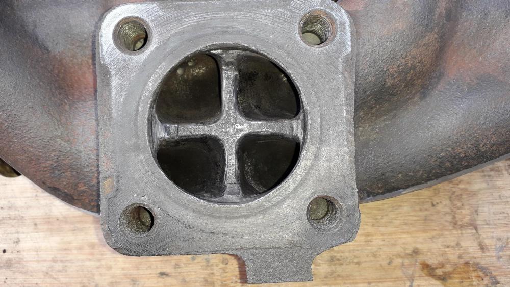

-
Claymore's sleeper 4efe+t-t+t build (R.I.P. the Nanza)
Claymore replied to Claymore's topic in EP91 Progress Blogs
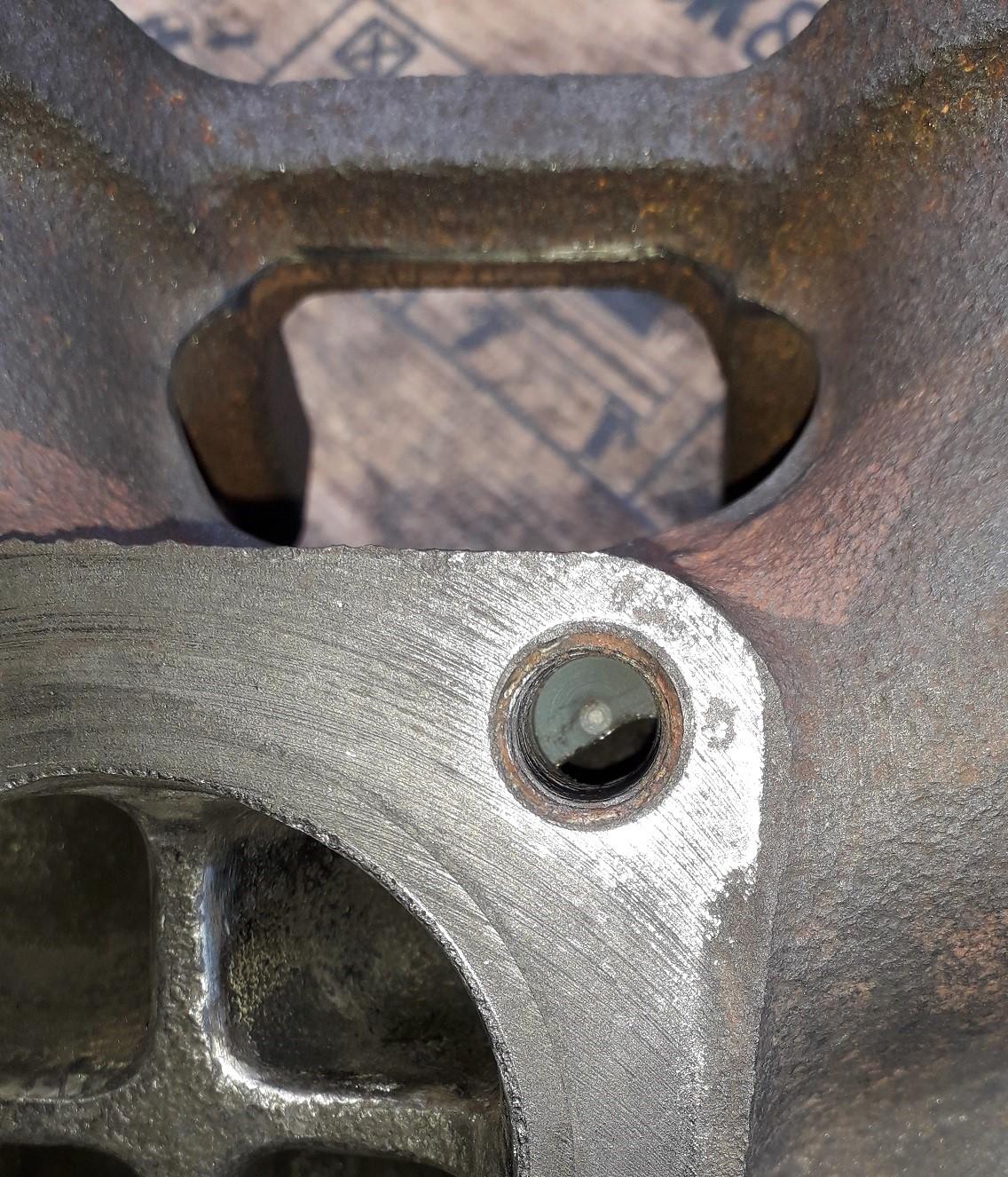
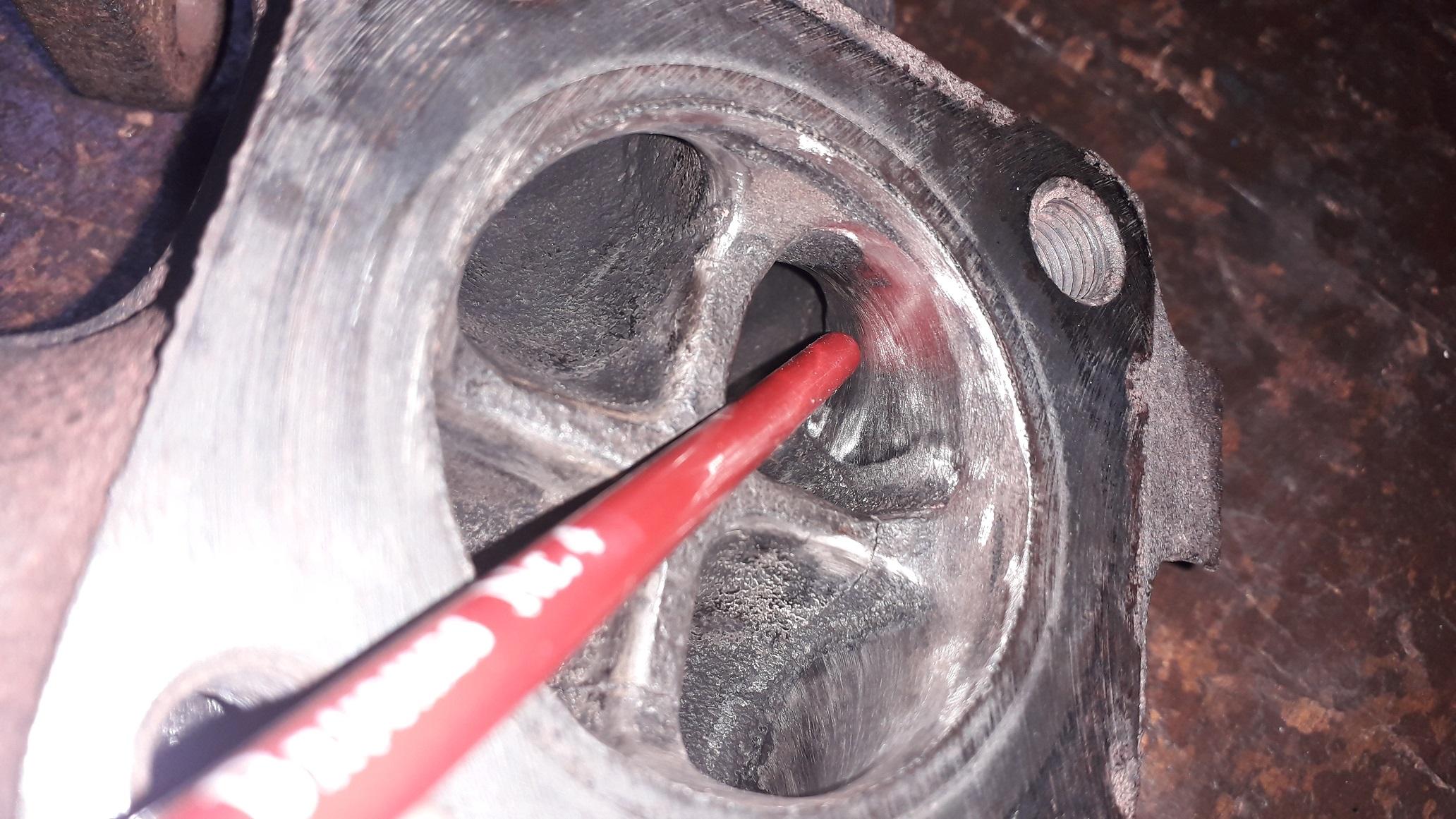
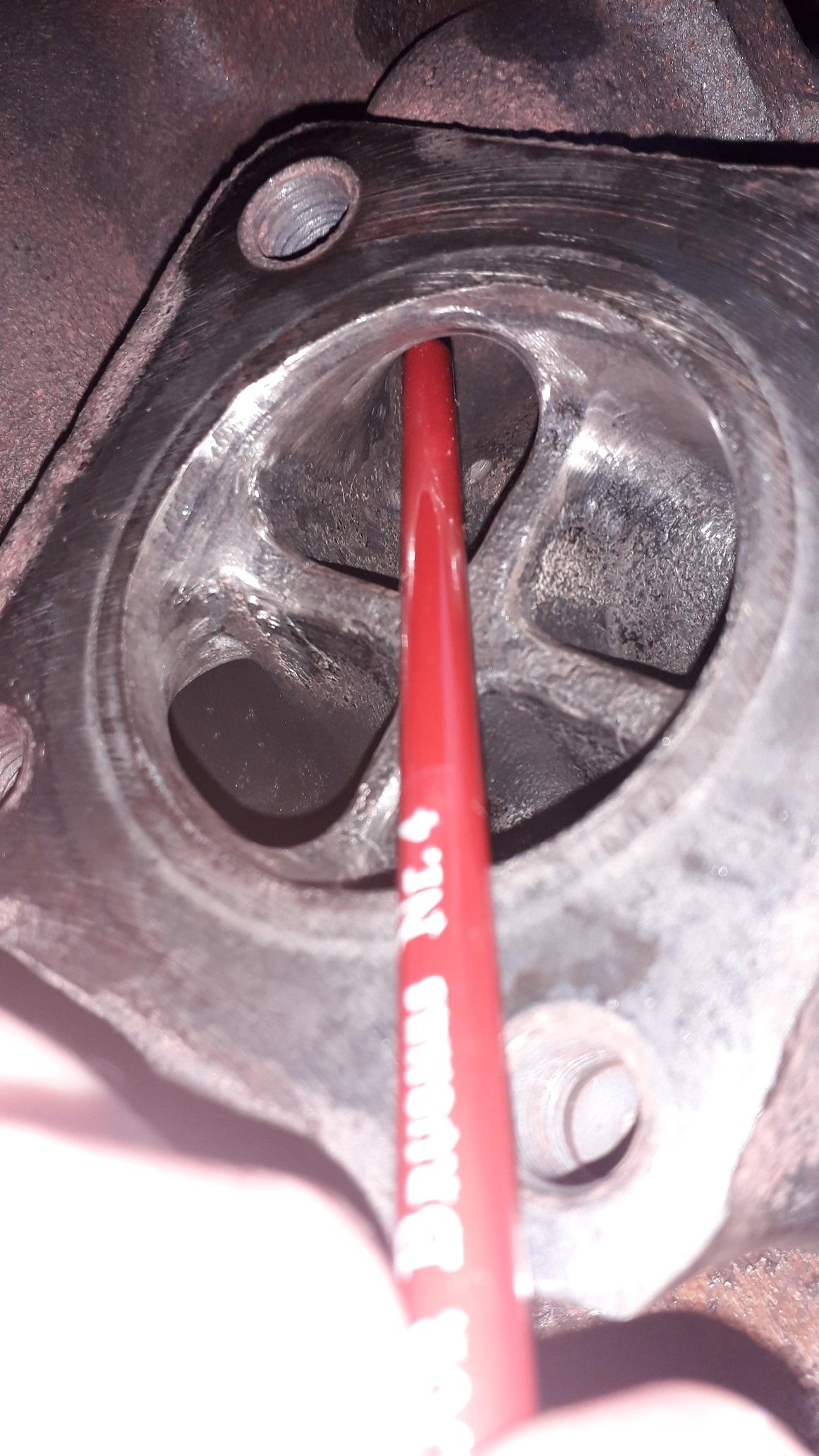
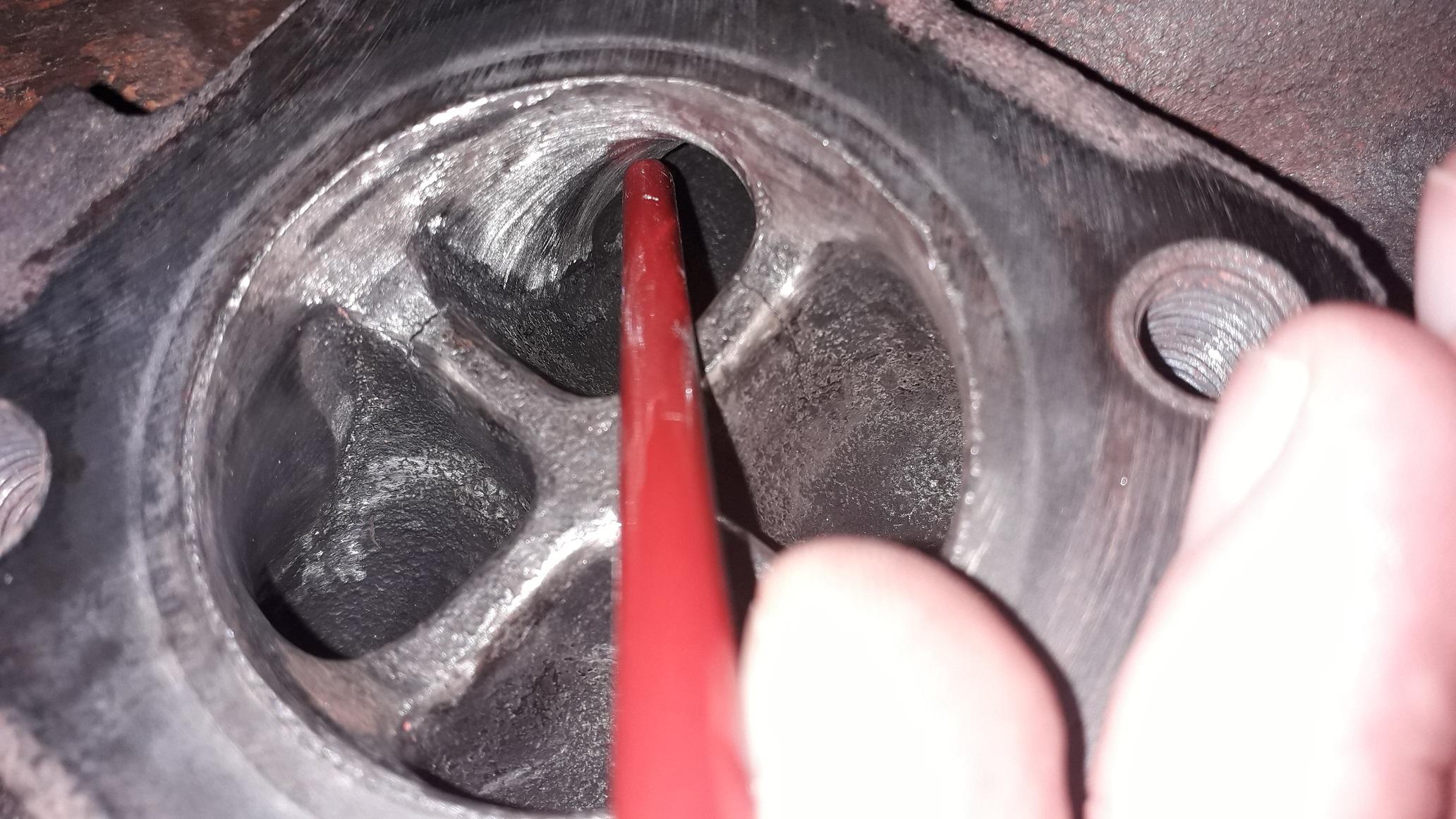
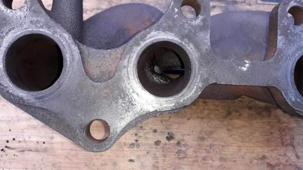
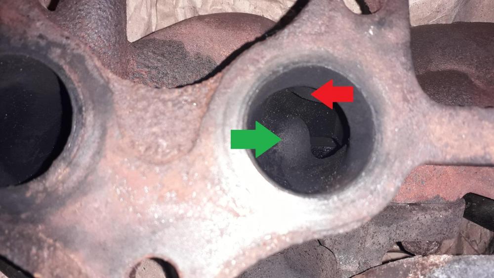
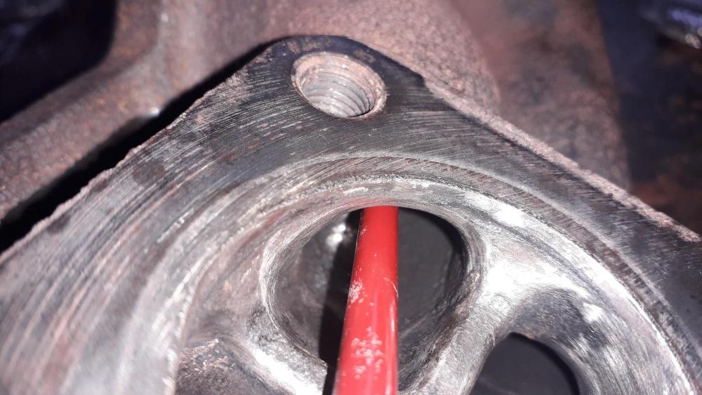
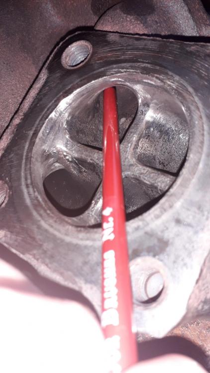
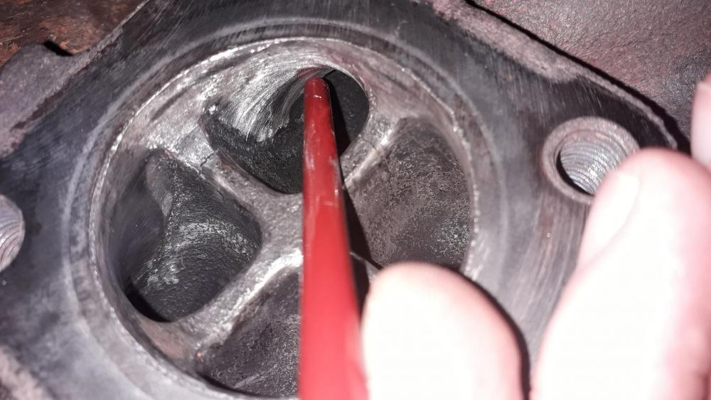
Then I moved on to the main event, the obstructions in runners 2, 3 errrr 1 and 4! Used an air die grinder with a long and short carbide burr to remove the majority of the material. Size was 10mm diameter x 20mm length round nose. Good size and the round nose is always useful in confined spaces. Grinder for stage 2 and sanding drum to finish. View of no. 3 runner restriction, I removed the green arrow restriction and left the red arrow lump as is because that section of the mani is only approx. 6mm thick. No. 1 runner had excess material here narrowing the runner. After removal. No. 2 runner had a lump where the stud is mounted, not as bad as 3 but still needed to be removed. Not easy as you can only see it from the turbo side so had to attack it from both ends. Using the long burr, my best judgment and lots of feeling around I managed to remove the other half of the lump from the head side of the mani. After removal. No. 3 largest lump under the stud. Easy to remove from both sides with the carbide burr. After removal. No. 4 runner same as no. 1. Excess material narrowing the runner. After removal.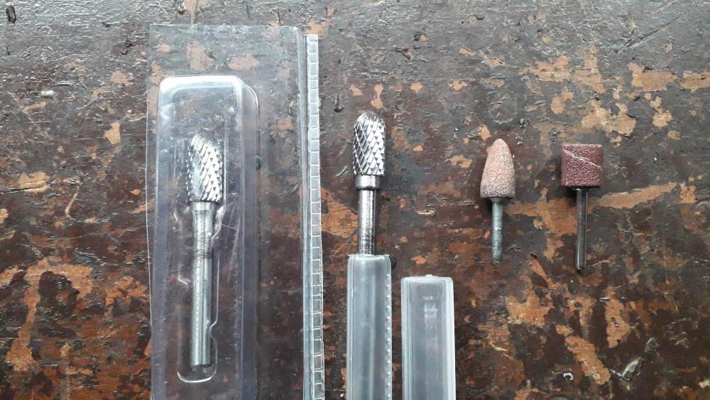

-
Claymore's sleeper 4efe+t-t+t build (R.I.P. the Nanza)
Claymore replied to Claymore's topic in EP91 Progress Blogs
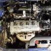
4efte cast exhaust manifold porting. Its no secret that the stock exhaust manifold has some "issues" regarding flow. In the interests of saving money I decided to go old school and port a cast manifold for the turbo install. So.... included in the turbo bundle was a manifold. Using the double nut method (tightening one nut to another to lock them to the stud) I removed the turbo mounting studs. WD40 and some bravery got them out fine, was dreading a snapped stud but all good in the end. Had to remove them to allow access with the die grinder rather than being restricted by the 4 x studs. Decided to do the easy, clean up stuff first, so removed the seam from the inside of the turbo flange. (We'll all be ignoring the 2 x hairline cracks from now on please) Not much to remove so I opted for the grinding stone on the dremmel. It shows the different size and shapes of the runner exits quite well. Also de seamed the outside of it with an angle grinder and sanding disc to generally tidy it up.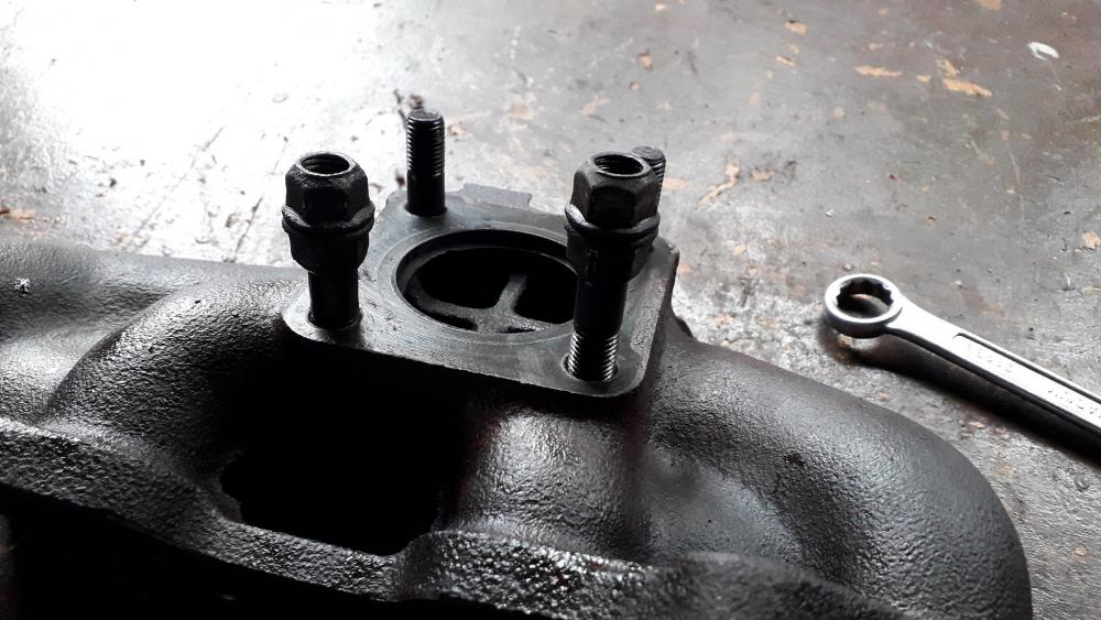


-
Picture regarding PM
-
Found this channel and thought it might be of use to some people. If you checkout the playlist tab it has a Toyota c transmissions build section.
-
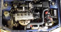
Does the tiny tb have a part number on it you can trace? Also the top left tb in the first pic has the plastic cable quadrant pulley and a different ICV, think it's from the bug eye corolla.
-
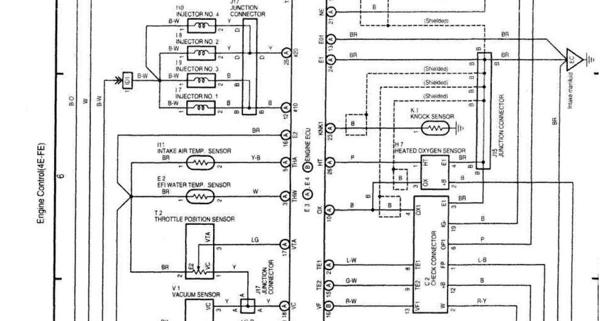
Yep its totally bonkers! Which is why I asked what engine is in the car, apparently there was an option of 2E and a diesel for some countries? Never seen or heard of one though. The UK 4efe (96/97) has a black signal wire for the tacho on the brown plug at position 6. This wire is shielded to stop any interference. The photos above show a pink wire in place?! I would use the diagnostic port signal, there was a guy on here who used a spade connector and just plugged it in to the port so there was no need to cut the wiring but the port cover will have to be left open. The green wire from the distributor is to communicate with the ecu to run the engine so I'd leave it alone unless absolutely necessary. Again this is all UK model stuff! Think the later models from 98/99 are different also! The fuse box certainly is anyway. From what I've read people have used the plastic circuit on the back of the clocks to trace the wires. Start with one plug and write down its wire colour and position. Then follow the tracks in the plastic circuit to see where it goes on the clocks, repeat for all plugs. Then do the same on the new clocks (following from the item on the clocks back to its connector pin). Then you know what the car wires do and where they should go on the new clocks. Then find a suitable feed for the missing wires. Not too difficult, just take your time.
-
I've had a look through the wiring diagrams I have for the UK 96/97 starlets and the wire colours / positions are different to your photos. Are the plug photos as Toyota made them or after you started moving things? Also what engine has the car got? The signal for the clocks comes from the distributor wiring on a UK model. But you can use pin 21 at the ECU instead or the one found in the diagnostic port also.
-
Claymore's sleeper 4efe+t-t+t build (R.I.P. the Nanza)
Claymore replied to Claymore's topic in EP91 Progress Blogs
Thanks mate, even my build thread's a sleeper lol. -
This sentence made me lol! So true nowadays. Sorry to hear you had trouble mate, I buy and sell quite often on eBay and the admin always sort it out well. Wouldn't touch FB marketplace with all the stories you hear. Thanks for the heads up.
-
Good stuff mate. 😎
-
4efe SWAP to 4efte in Corolla E11 1998
Claymore replied to Frankieflowers's topic in 4E-FTE Engine Discussions
Thought that's what you meant. Best to clarify on the forum though as we don't want people asking for 220bhp! Rods out please dyno man! All the professional tuners I've spoken to and historical builds seem to aim for the 160bhp mark 4efe+t. -
4efe SWAP to 4efte in Corolla E11 1998
Claymore replied to Frankieflowers's topic in 4E-FTE Engine Discussions
Personally I'd get the engine health checked as you described and if ok then aim for 150ps 4efe+t build but that's what I'm building as a project so I may be biased. Will be interesting to see the bhp figures on Stevie82 and my builds when complete, we are pretty much building to the same specs although Stevie may be a bit more secretive with his as his is a competition car (totally understandable ). My engine only has 42k miles on it so should be healthy! Quite a lot of turbo parts on eBay in the uk recently with higher than average prices though, but parts may be more difficult to find in Italy. It's Frankie's choice now. -
4efe SWAP to 4efte in Corolla E11 1998
Claymore replied to Frankieflowers's topic in 4E-FTE Engine Discussions
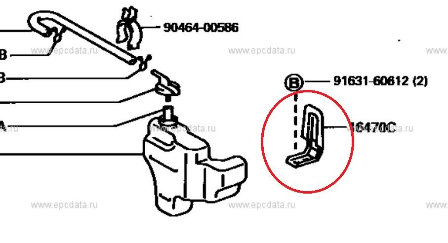
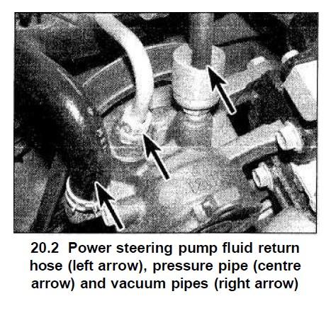
I think 220bhp may be a bit optimistic for a reliable daily driver with a 4efe + t. Especially considering the engine in the car has covered 200k km? I understand the injectors will flow enough for 220hp with a 255lph walbro but I wouldn't recommend tuning a 4efe + t to that power level. Also need to add an air filter and pipework and 255lph walbro fuel pump to the list above. Bonus is that the corolla engine has a knock sensor as standard: The only other thing is the power steering pump on the corolla has the air control valve on the pump whereas the starlet has it on the steering rack instead so this feature will be lost.
-
Claymore's sleeper 4efe+t-t+t build (R.I.P. the Nanza)
Claymore replied to Claymore's topic in EP91 Progress Blogs
https://www.midlandturbo.com/ -
Probably best to change the gearbox oil as well. Unless there is a receipt for it being done recently, it's quite often overlooked.
-
Claymore's sleeper 4efe+t-t+t build (R.I.P. the Nanza)
Claymore replied to Claymore's topic in EP91 Progress Blogs
I was amazed at the difference when I got it back. The guy on the phone said "essentially it will look and perform like a new turbo" I was sceptical until I saw it. It's awesome -
Claymore's sleeper 4efe+t-t+t build (R.I.P. the Nanza)
Claymore replied to Claymore's topic in EP91 Progress Blogs
Thanks guys, I'm really looking forward to the next part of the build -
There are no daft questions mate! Wouldn't say there was any special maintenance because an engine is forged, it's more the power level and how it's driven that will reduce service intervals. Most track cars get an oil and filter change after each track day due to the nature of the driving. If it's sensible power output and mixed street driving then the normal change intervals should be fine. If you wanted to be safer then reduce the oil service interval to 2k miles. Always use quality fully synthetic oil of the correct grade and a quality oil filter. Avoid separate oil additives and oil flushes, imho they aren't necessary as modern oils are excellent and have all the detergents and additives required already.