Claymore
-
Posts
660 -
Joined
-
Last visited
Content Type
Profiles
Forums
Wiki
Media Demo
Events
Everything posted by Claymore
-
No word from KYB hope they bothered looking in to it. I did research it a bit myself and I strongly believe that these mounts are for the EP82 (4 fixings and a larger shock absorber shaft diameter). I agree about the price and worth of Toyota O.E. components. They seem expensive but when you factor in the quality and how long they last its probably cheaper than buying aftermarket twice in the long run. Your Starlet has the different style top spring perch as well. Fits inside the spring where as mine is the earlier type that fits over it. Nice to see.
-
Glad I could help out mate, good job getting them changed out. 👍 If anyone needs more info check out my build thread for part numbers and measurements. Sucks having to do jobs twice, my old top mounts were ok to use again but I'll have to change them sooner rather than later. Gonna get genuine Toyota replacements to make sure they're right.
-
Claymore's sleeper 4efe+t-t+t build (R.I.P. the Nanza)
Claymore replied to Claymore's topic in EP91 Progress Blogs
Thanks it took a while but I'm proud of the results. @JamesG I'm sure you're aware of how the PCV system works and its intended purpose. In my opinion it is important to ensure that however you choose to attach the catch can (cans!?) and route the piping that the vapours are drawn from the crankcase under vacuum (supplied by the inlet manifold and pre turbo pipework). I don't like the idea of the vapours being pushed into the crankcase and being allowed to find their way out of breathers on their own creating neutral or positive pressure in the case. Your build shows you know how things should be done so I have every faith you'll get it right anyway. And for gods sake no-one buy this! : https://www.ebay.co.uk/itm/Toyota-Starlet-race-spec-black-rocker-cover-EP82-EP91-GT-Turbo-Glanza-V-4EFTE/233726275713?hash=item366b2bf081:g:FdMAAOSw4slfbxMe Its only £80 and is still full of swarf from installing the fittings! 😱 -
Claymore's sleeper 4efe+t-t+t build (R.I.P. the Nanza)
Claymore replied to Claymore's topic in EP91 Progress Blogs
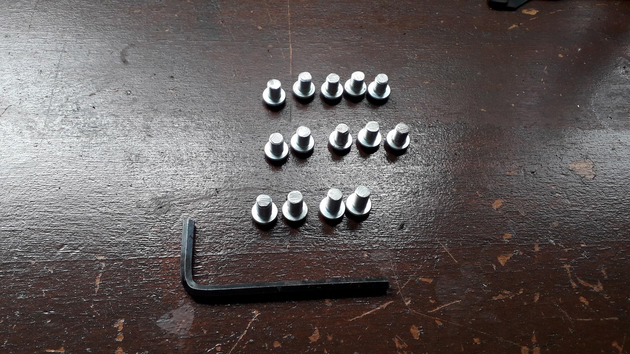
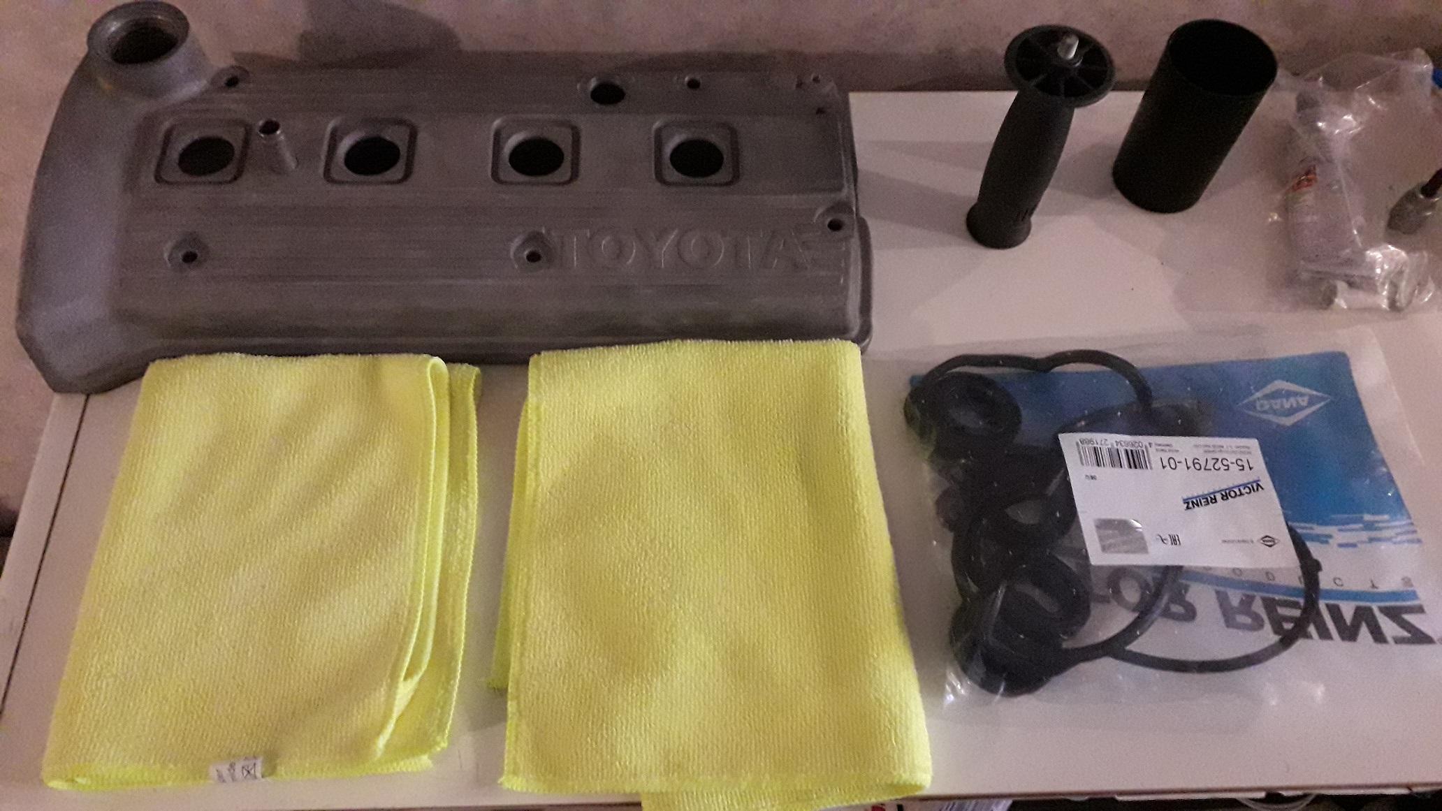
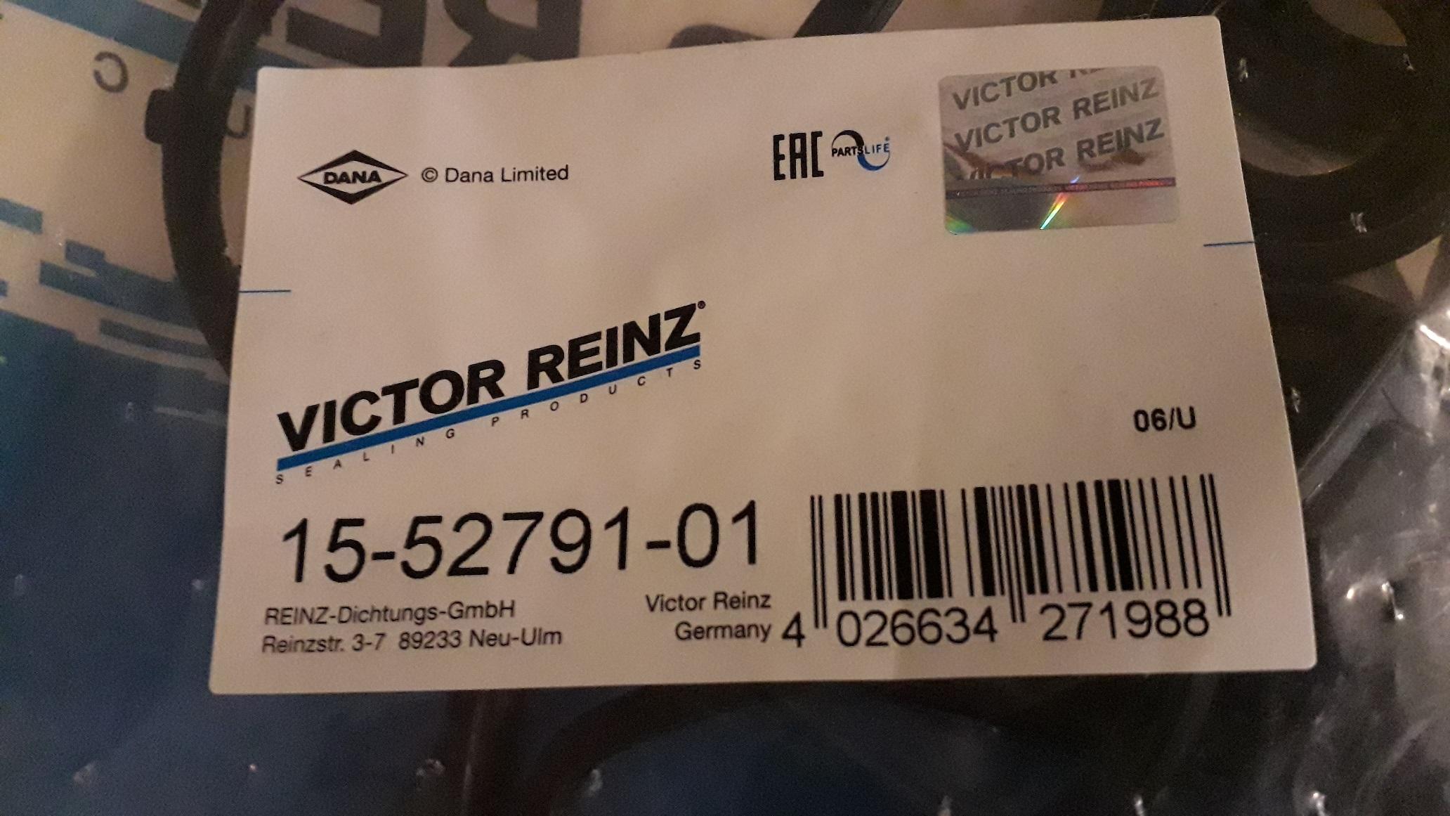
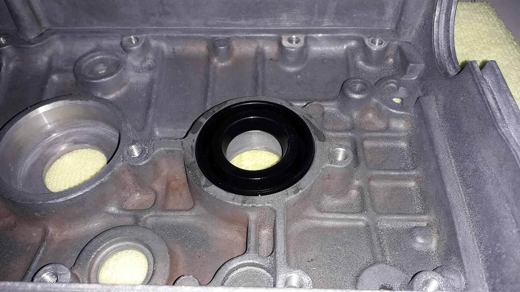
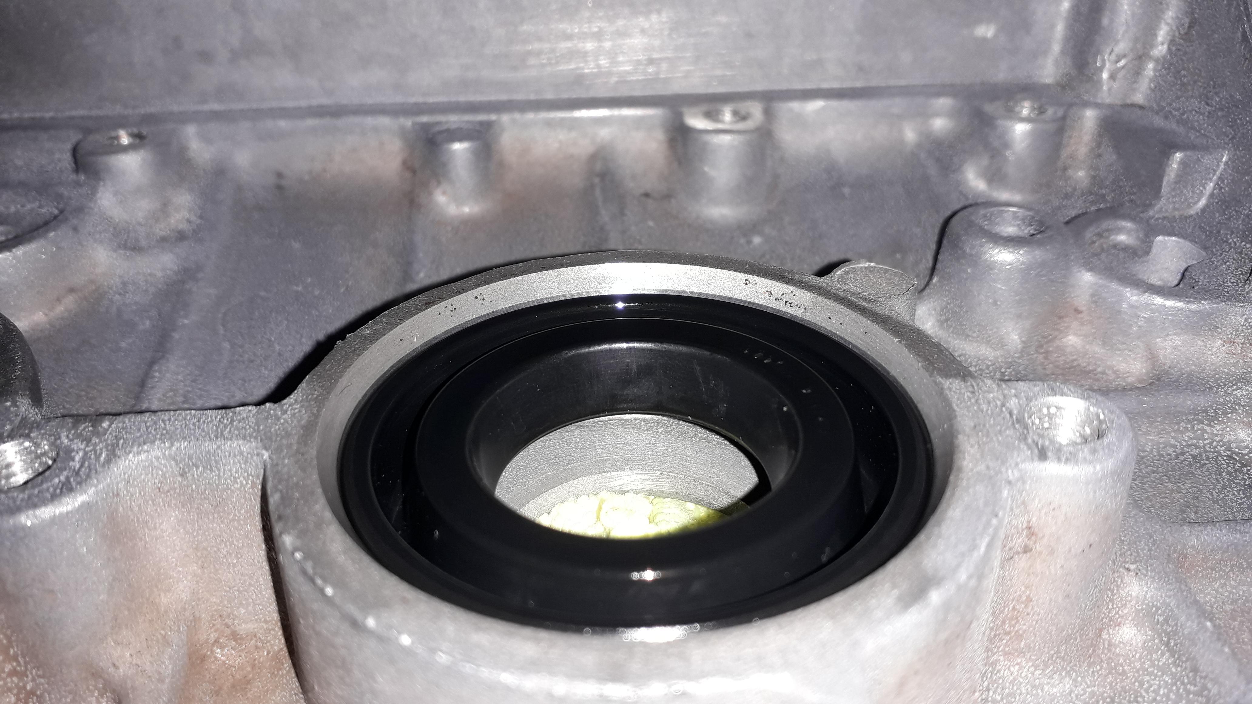
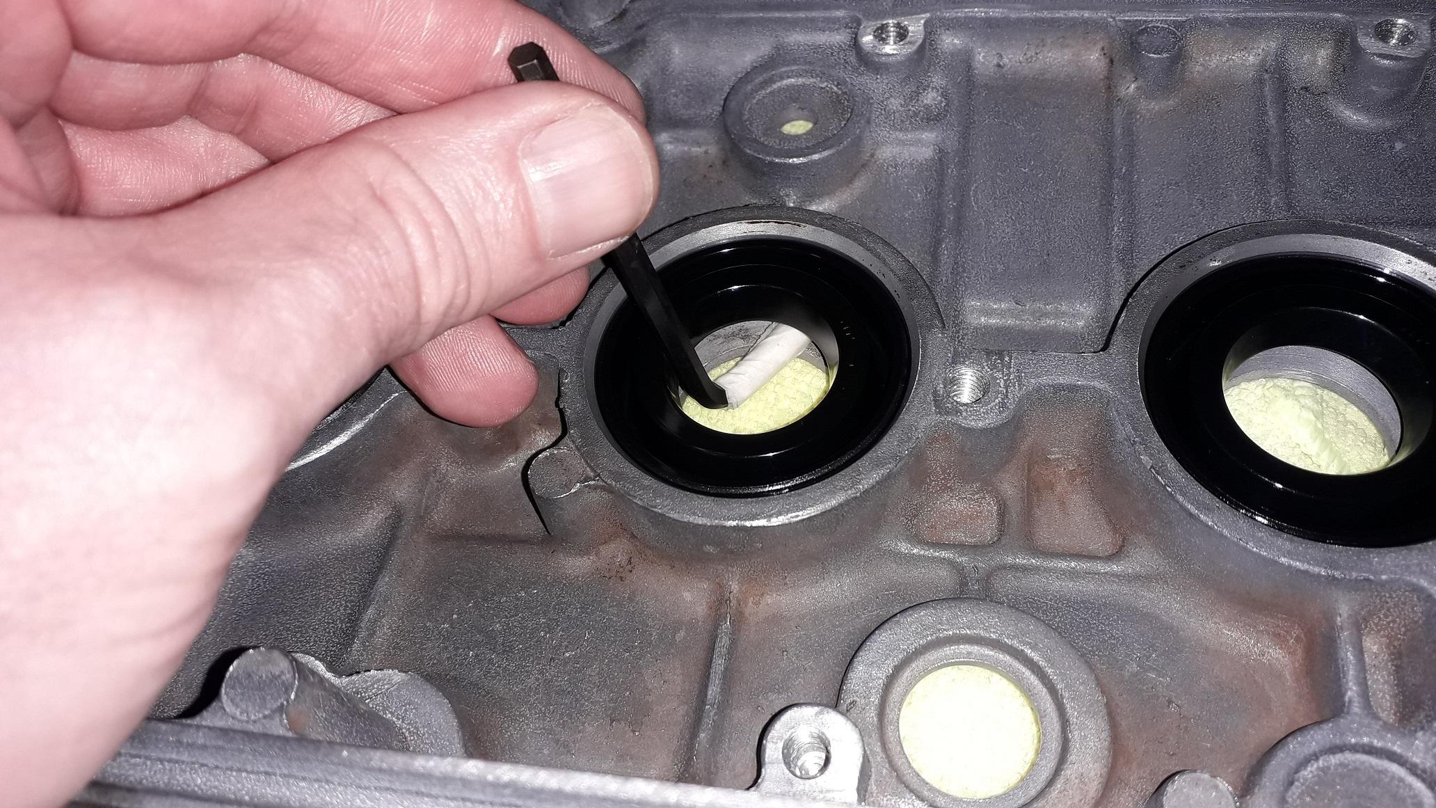
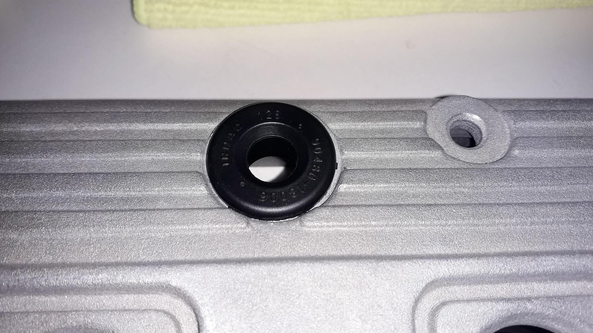
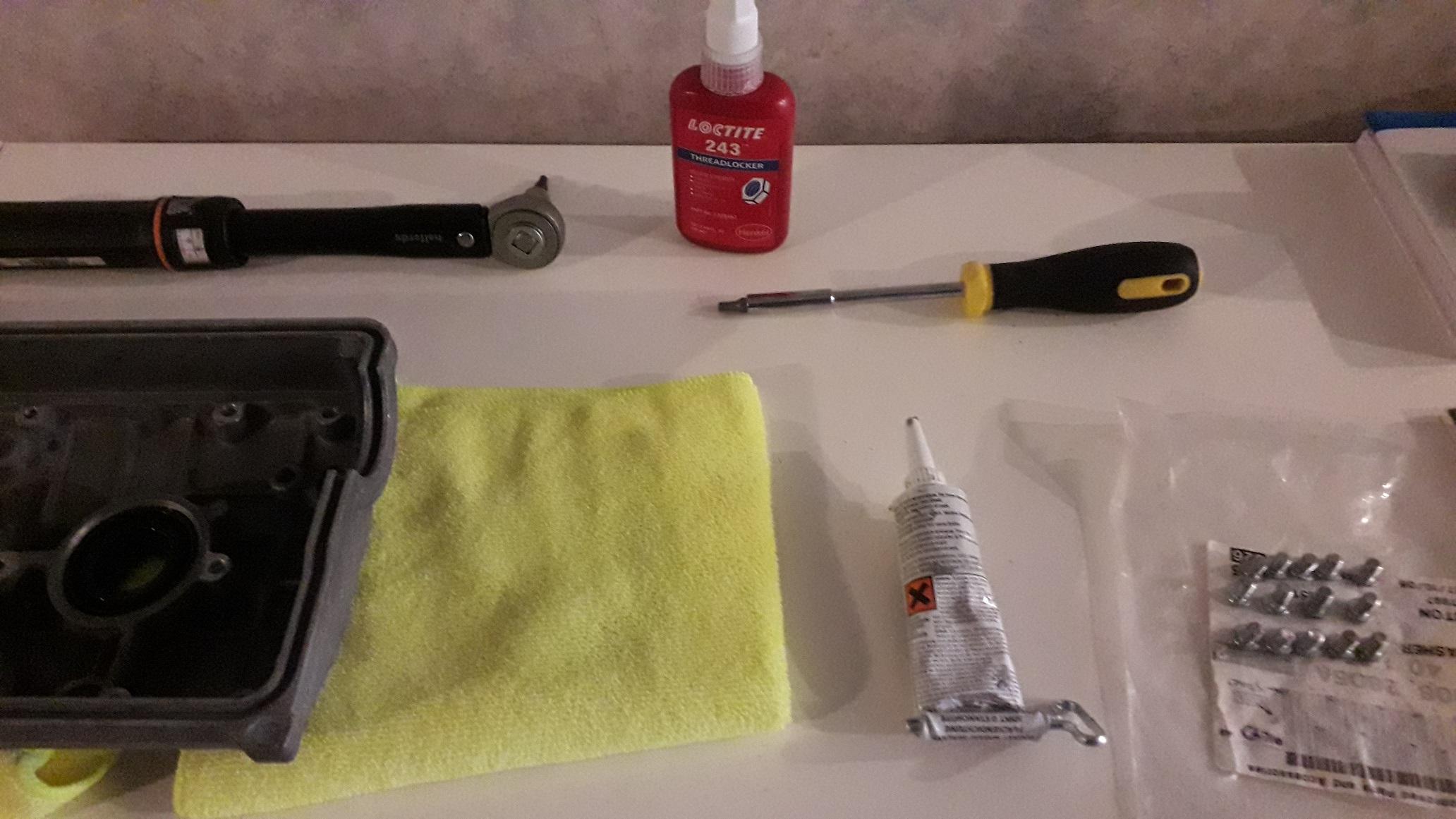
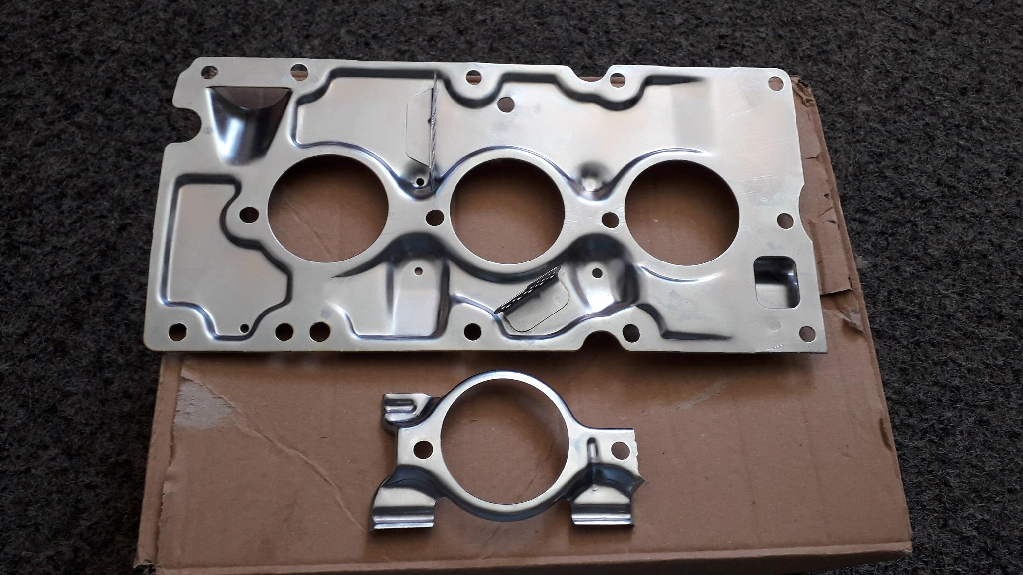
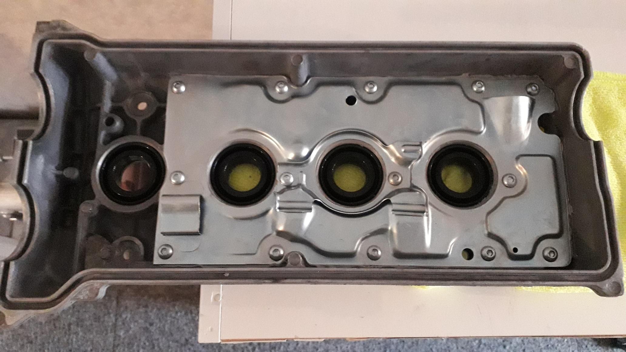
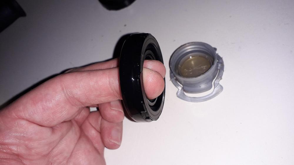
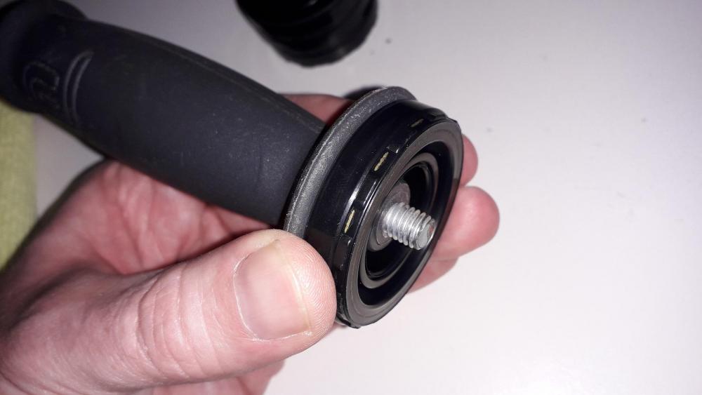
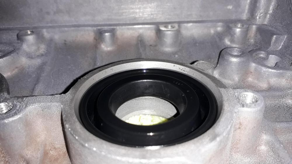
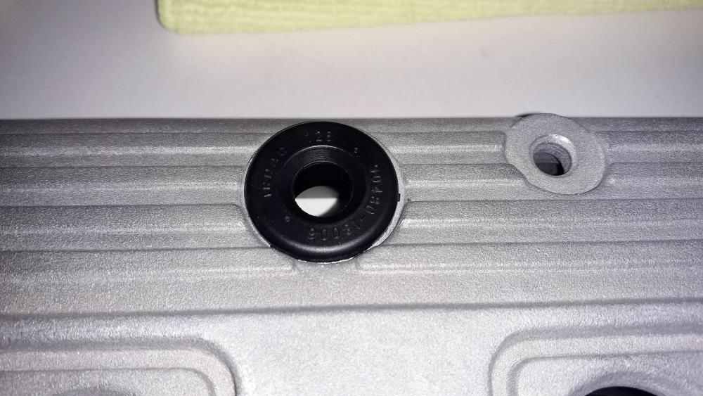
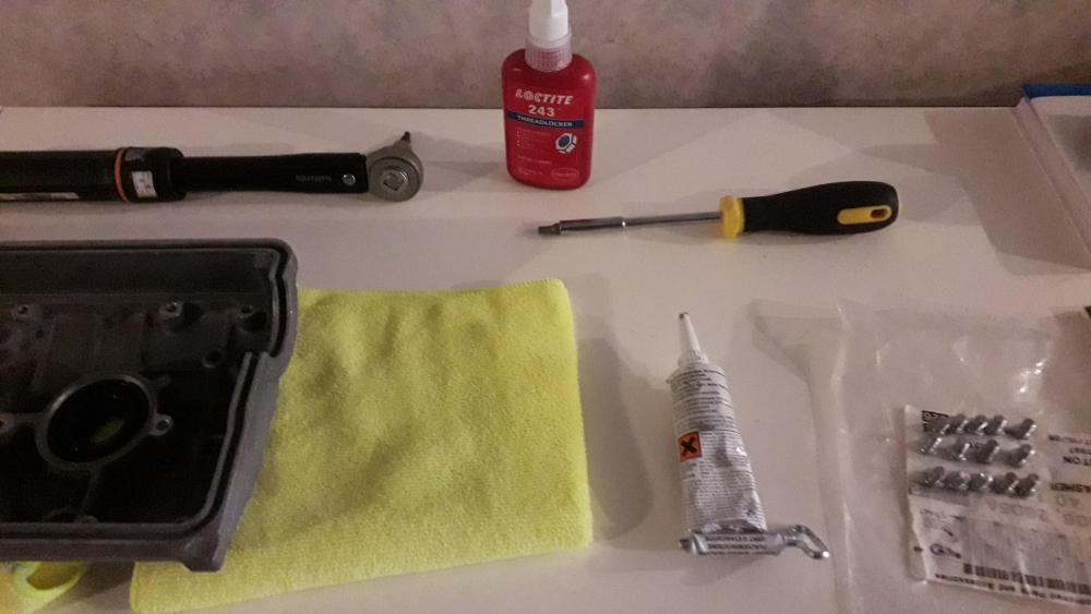
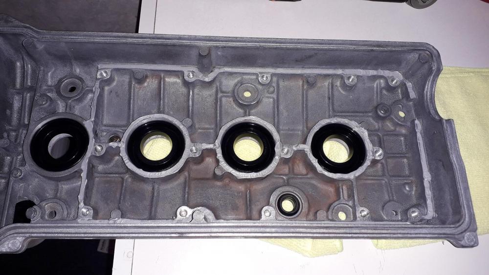
4efte cam cover. The re-assembling. Being as the weather has been absolute sh!te recently I decided to do some indoor jobs. Mainly the one I'd been putting off for months. I had already cut down the M6 screws to the required length earlier in the month, 14 required, shortest on the outer rows and longer in the middle due to the curved outer design of the cover. Chose button head socket screws as these have the lowest profile head for their size and fitted the baffle recesses well. All laid out ready to start, clean environment to reduce the risk of contamination. Bought the Victor Reinz gasket set. Part number: 15-52791-01. Includes main gasket, spark plug seals and rubber lined washers to attach cover to head. Seals were nice and pliable (compared to the hardened old items I removed) but also a bit sticky so I lubed the outer surface up with engine oil prior to fitting. Pressed them in by hand to start. I only put pressure on the outer edge as the inner ring is flexible. Remember to get them the correct way round! I found that the handle from my angle grinder was the exact size needed to press the seal in the rest of the way. I set the seal at a depth I felt made sense! The edge was level with the bottom of the chamfer. (approx. 2.5 mm sub flush from the baffle surface). This should allow plenty of room for the spark plug tube to seal with out making the seal difficult to extract if its pushed in too far. Speaking of pushing one in too far (filthy!) the second seal tilted a bit on one edge, so I wrapped an allen key in masking tape to "soften" it and gently levered the wonky side back into place. Continued until all fitted well. Then I inserted the PCV grommet. Toyota part number: 90480-18006. Time for the fun part! Had the baffles re plated as I had accidentally stripped some of the original coating off during the clean up process. Bright zinc plated, 7 microns thickness, clear passivate. Degreased the surfaces with brake cleaner to allow the sealant to adhere. Then I laid down a thin bead of Loctite 5699 gasket / sealant to replace the original card Toyota gasket. Placed the large baffle in to position and swum it around to help the sealant mate to both surfaces. Added threadlock 243 to a bolts threads and a drop onto the threads in the corresponding blind hole in the cover (just in case). Screwed it in loose and repeated for the rest at speed. Hand tightened and then fully tightened all screws to 10Nm with a torque wrench. This should be plenty and with the additional 20Nm provided by the cured thread lock. Didn't take many photos of that step of the process as I was aware of the gasket curing time, so the finished article is below. An bit of a mission from start to finish, but I enjoyed the process and am most happy that I managed to save another piece of NLA Toyota goodness for my project.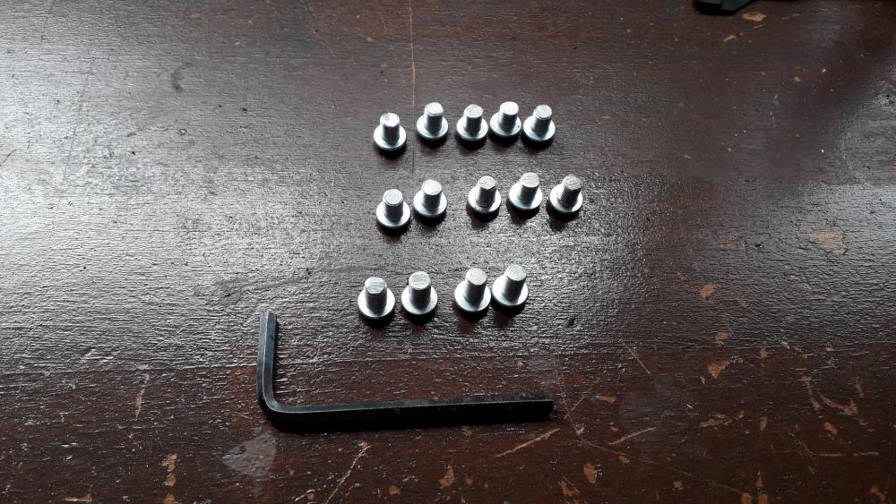


-
https://www.toyotagtturbo.com/community/index.php?threads/abs-diagnostic.28380/ They are separate codes. It appears there is no ABS code 47.
-
According to this: Code 47 = Throttle Position Sensor (TPS) or Circuit. The glanza's use a different throttle position sensor from auto to manual. Did you swap everything from the manual car? Loom, throttle body, ECU, etc? Never done it myself but I hope this helps point you in the right direction.
-
Cheers, I get it right most times (I think!?). The rest of the time I'm still happy to learn something. Thankfully the Emanage blue (most popular?) uses an external MAP sensor that can be placed close to the manifold with a long electrical connection so should be better than the onboard piggy's. Currently figuring out my vac hose needs and positions, would be easier if I could use the fte manifold as it seems to have plenty of options for vac take off's rather than the fe or corolla manifold which are limited. The fe is probably easier as the aluminium looks thick enough to be drilled and tapped for hose barbs unlike the rolla mani that has insufficient wall thickness to take the threads. Weld on threaded boss's might be an option.
-
Stumbled across this the other day thought you'd be interested, I posted it on the Holset thread but don't know if you saw it. Full credit to Kris H. https://rennlist.com/forums/944-turbo-and-turbo-s-forum/853894-turbocharger-compressor-and-turbine-maps-mega-thread.html
-
Totally agree, Toyota probably chose the firewall position to put the sensor in a safer environment and allow it to be used on different manifold designs etc. This led to the the vac hose and filter which will cause a small delay. When it comes to modifying I understand that it's all up for improvement and its nice to know that moving it hasn't caused you a problem and you could use the original sensor. I have always been a bit apprehensive about the length of vac hose required to link the manifold and built in piggy back map sensor (about 1m away in the glovebox!). Thankfully I will only be using the det3+ onboard map for boost control not fuelling. I should be able to datalog the delay between Toyota MAP and det3+ MAP signals. That's what I like about your project, it always gives me something to think about. 👍
-
I meant an actual filter in line (as fitted by toyota 23265) which has the effect of smoothing the map sensor fluctuations. I had a fuel pulse damper on my old weekend toy and I removed it with no ill effects when it failed and was NLA from the dealer. I understand its function and sometimes its is only fitted to reduce NVH into the cabin rather than a weird conflict that can cause lean spots or fuel delivery problems. Quite a few aftermarket FPR's have this feature built in nowadays any way. I've checked the online Toyota parts catalogue and it is only listed for the very early 96 model 4efe and not listed for the 4efte at all. Maybe Toyota realised it wasn't necessary on a stock car. Hope you figure out if there is actually a problem, just remember your own advice Sam, try not to get carried away!

-
Weird, I remember an aussie guy saying that he was reading boost fluctuations of about 1psi (I figure from the wastegate regulating boost pressure) and this in turn was causing fuelling issues as the ecu was reacting to the wavy boost signal. He said that after reinstalling the inline "filter" (damper in reality) the fluctuations were halved and reduced the fuelling issues to an acceptable level. He had some very good data logs that showed it well. I was going to suggest a different MAP sensor (perhaps Honda k-series) that was designed for direct mounting to manifold but no need. I'm sure that some aftermarket ecu's can electronically filter their input signals to prevent this also. The corolla intake manifold will solve the first problem. But if you're worried about uneven fuelling along the rail have you considered feeding from both ends and returning from the middle of the rail? Seems like overkill on a short 4 cylinder really but might help. Or feed fuel from the other end of the rail so the leanest injector is now cylinder 4? Just thinking out loud really!? 😕 Might show a difference in EGT on cyl 1 (or cause a meltdown!) Interesting stuff though.
-
What happened to the Audi twin plate throttle body? Did you manage to get it fitted and tested? Any pics? Also with the MAP sensor being relocated to the manifold have you experienced any pressure fluctuations or interference? I remember reading another build thread were the vac hose was shortened and the "filter" was removed and the owner experienced all sorts of fuelling issues because the lack of filter made the response too sensitive. Like the addition of EGT sensors pre and post turbo. 👍
-
Claymore's sleeper 4efe+t-t+t build (R.I.P. the Nanza)
Claymore replied to Claymore's topic in EP91 Progress Blogs
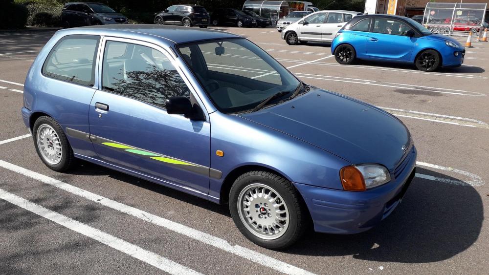
Thanks guys, I don't like cutting corners but I do like an experiment or two sometimes. Small details can make a big difference. Check out JamesG's thread if you like the details, very nice. Yes the 8k9 is probably my favourite colour, shame mine is sun faded but weirdly when I take photos in certain light it really looks purple! It reminds me of one of my first cars in design and also colour so it has inherited some nostalgic feeling already. Roll on the next round of mods! -
This is my outlook also, I have seen a few dyno plots and unless it's only one item that has been changed it can be difficult to attribute which change did what to the curve! My theory is stock is good for low down torque (longest, thinnest diameter runners, need to measure this to confirm), corolla should be better for mid range (shorter equal length, larger diameter runners) and fte manifold better top end (shortest, fat runners) assuming the revs are available. Also plenum size will change the characteristics, I've roughly calculated the corolla mani in my build thread and I'll do the same for the stock fe mani when its off. Hopefully be able to get some dyno runs for the first 2 atleast.
-
Thanks, I think the shorter runners are better for top end and the corolla equal length is better for low / midrange power depending on which build you read! ECU could play a part, also if the cams are different it may not "agree" with the rest of the characteristics i.e. all components best for low down torque etc. Might be better on a gen 2 I guess. Dyno will reveal all. I'm planning on using the corolla manifold on my build (gen 2, 4efe + t) Hope to get some dyno results with stock vs corolla manifold as the only change before turboing. Just wondering now what the fte mani would bring....although I only have a 6k ish rpm limit. Good to see you back 😎. Hopefully a forum revival is beginning.
-
Awesome build mate, thanks for taking the time to fix the photos. So many build threads ruined by the photobucket fiasco. Good work, looking forward to the updates. Was just wondering, you tried the corolla tubular intake manifold and switched back to the short runner fte style manifold. Can I ask why? I assume the power delivery changed or reduced?
-
You might be better off looking for a complete glanza boot lid. It should be complete with spoiler and number plate surround (which has the glanza reverse lights in.) Might be easier than trying to attach a spoiler to a starlet boot which won't have the holes / fittings to attach it. Welcome to the forum by the way 👍
-
Gt turbo rear spoiler ,£30 posted
Claymore replied to dangeestarlet's topic in Starlet Parts For Sale
Assuming it's an EP82 GT Spoiler will it even fit on an EP91 Starlet? Unless lewray2020 has an EP82 starlet as well? -
Just finished watching it. Hopefully its a 5efhe that's been turbo'd (intake manifold looks like 5e with the 16v EFi on it). Would be interested to see how it behaves on the dyno with the cams. Fingers crossed for a long build series rather than the short builds they sometimes do in between the long ones. 😎
-
Thanks for the offer mate, but I'll give my ones a chance. Fingers crossed.
-
Claymore's sleeper 4efe+t-t+t build (R.I.P. the Nanza)
Claymore replied to Claymore's topic in EP91 Progress Blogs
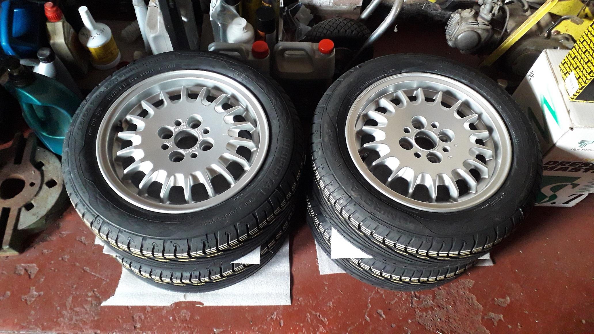
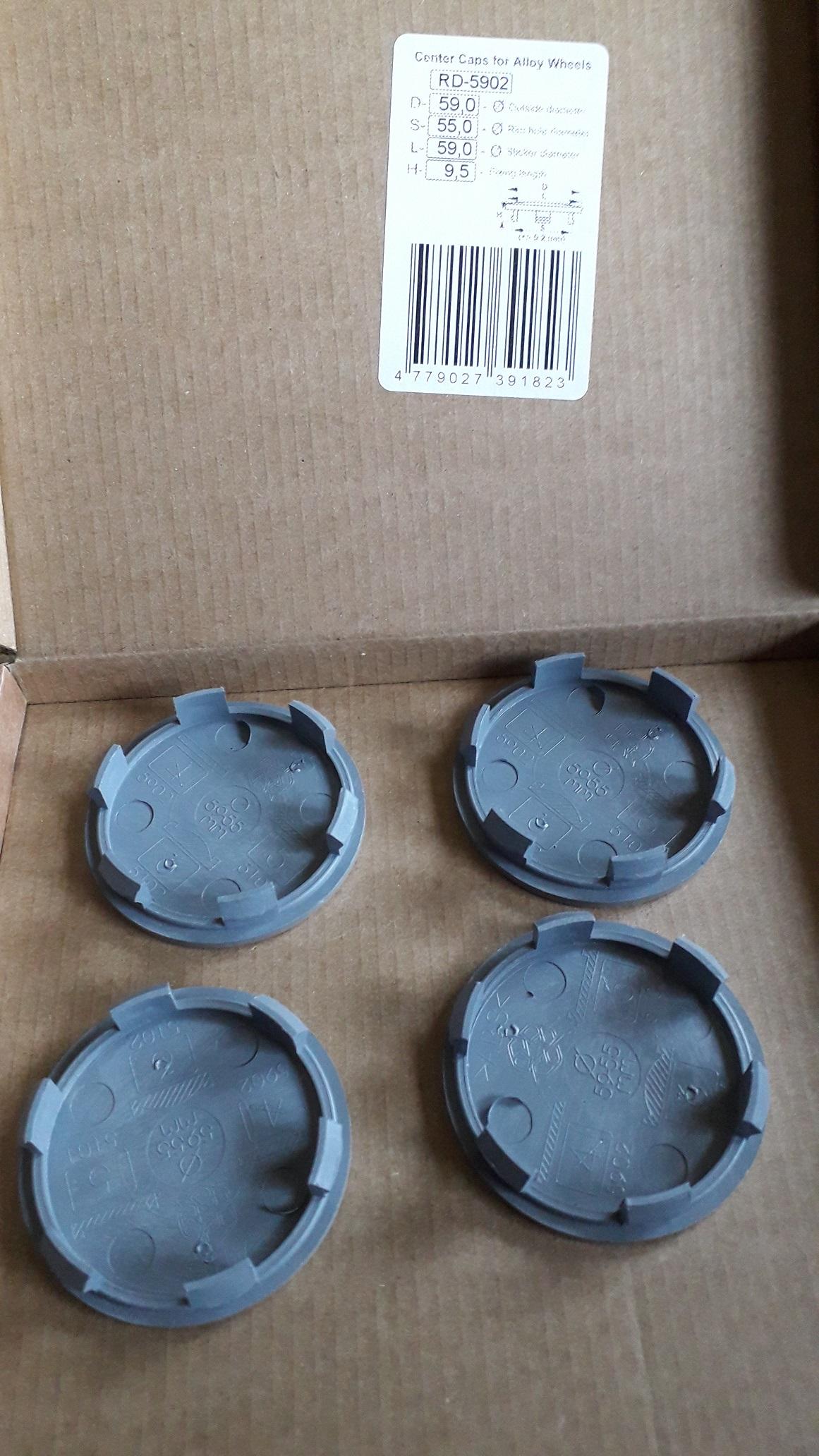
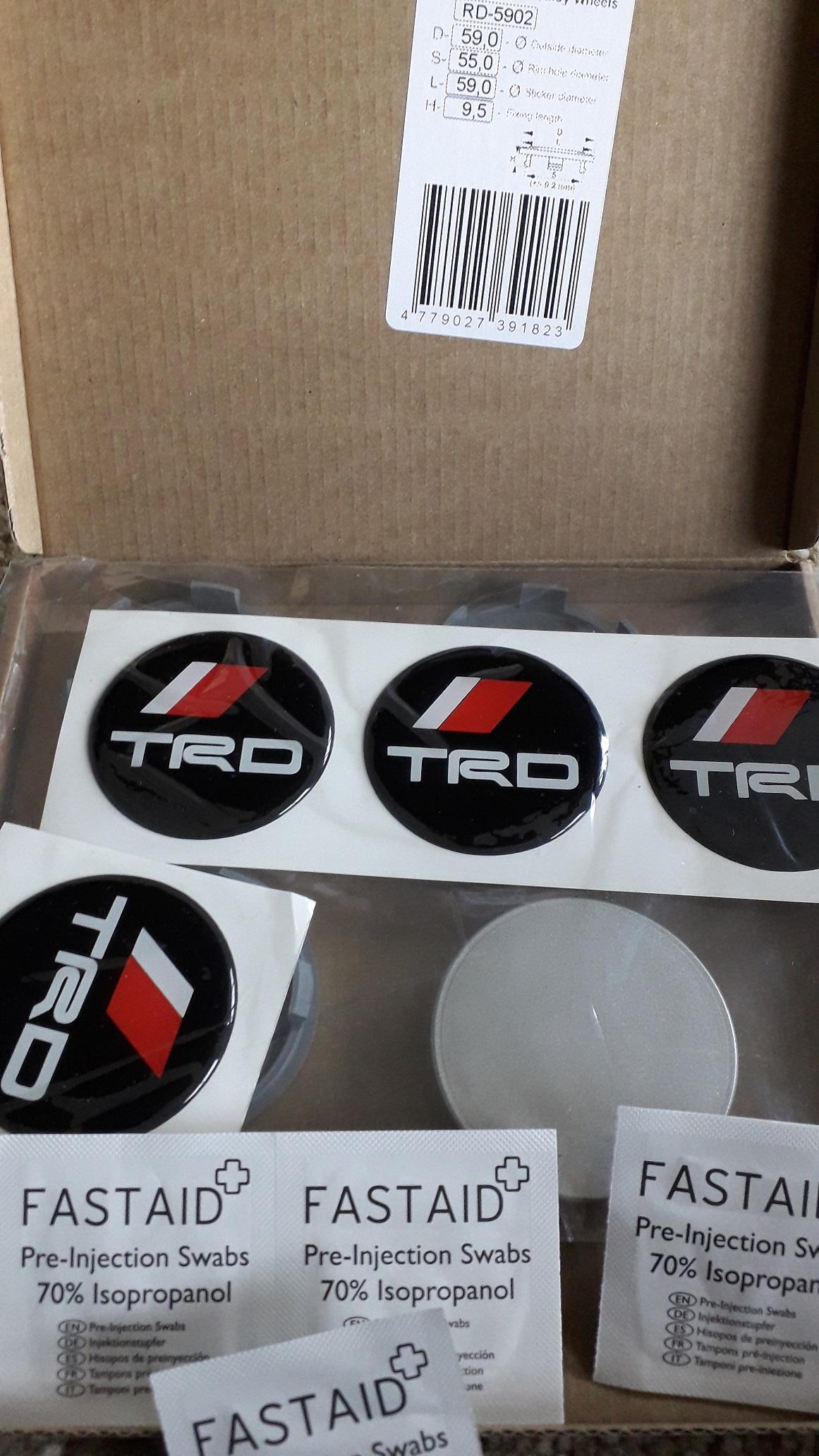
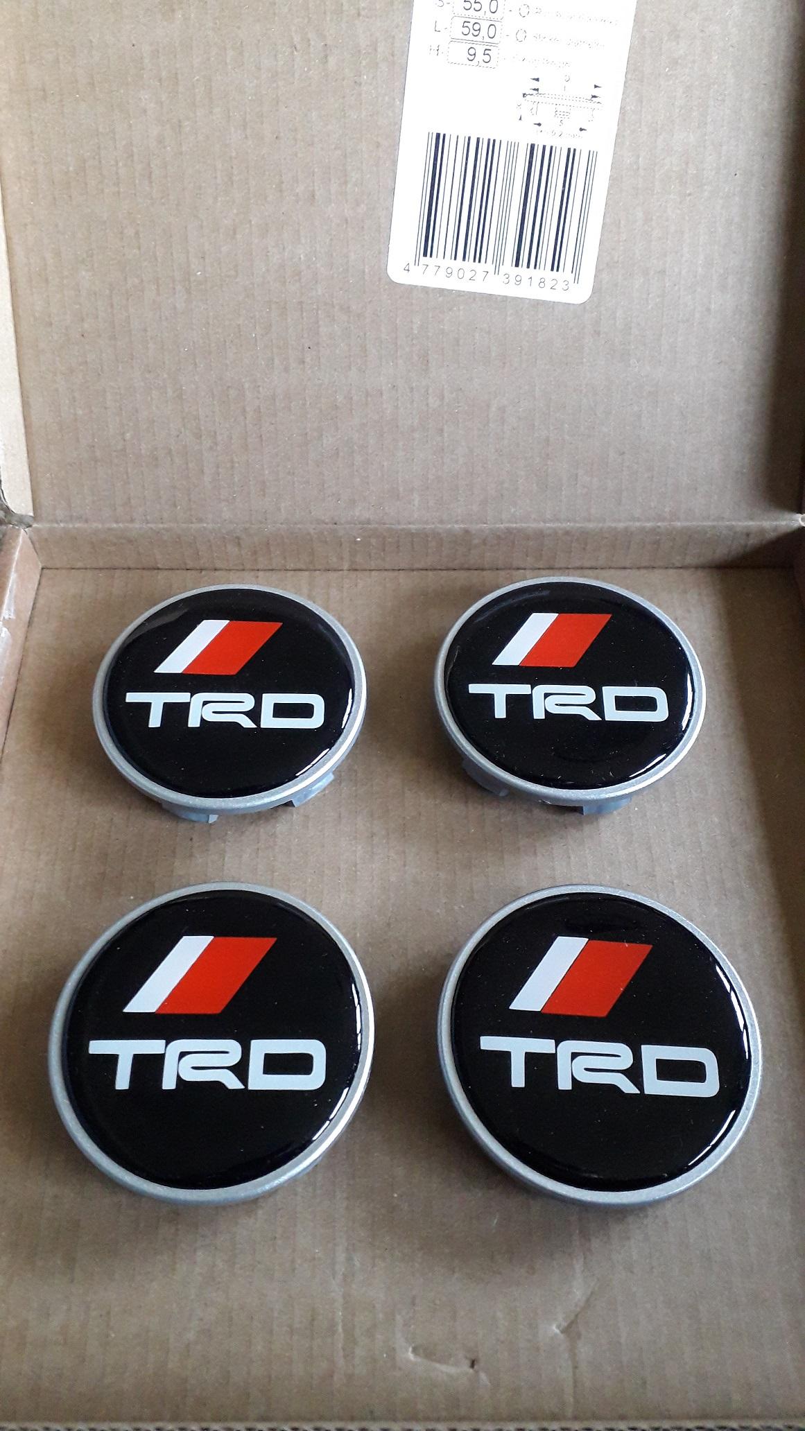
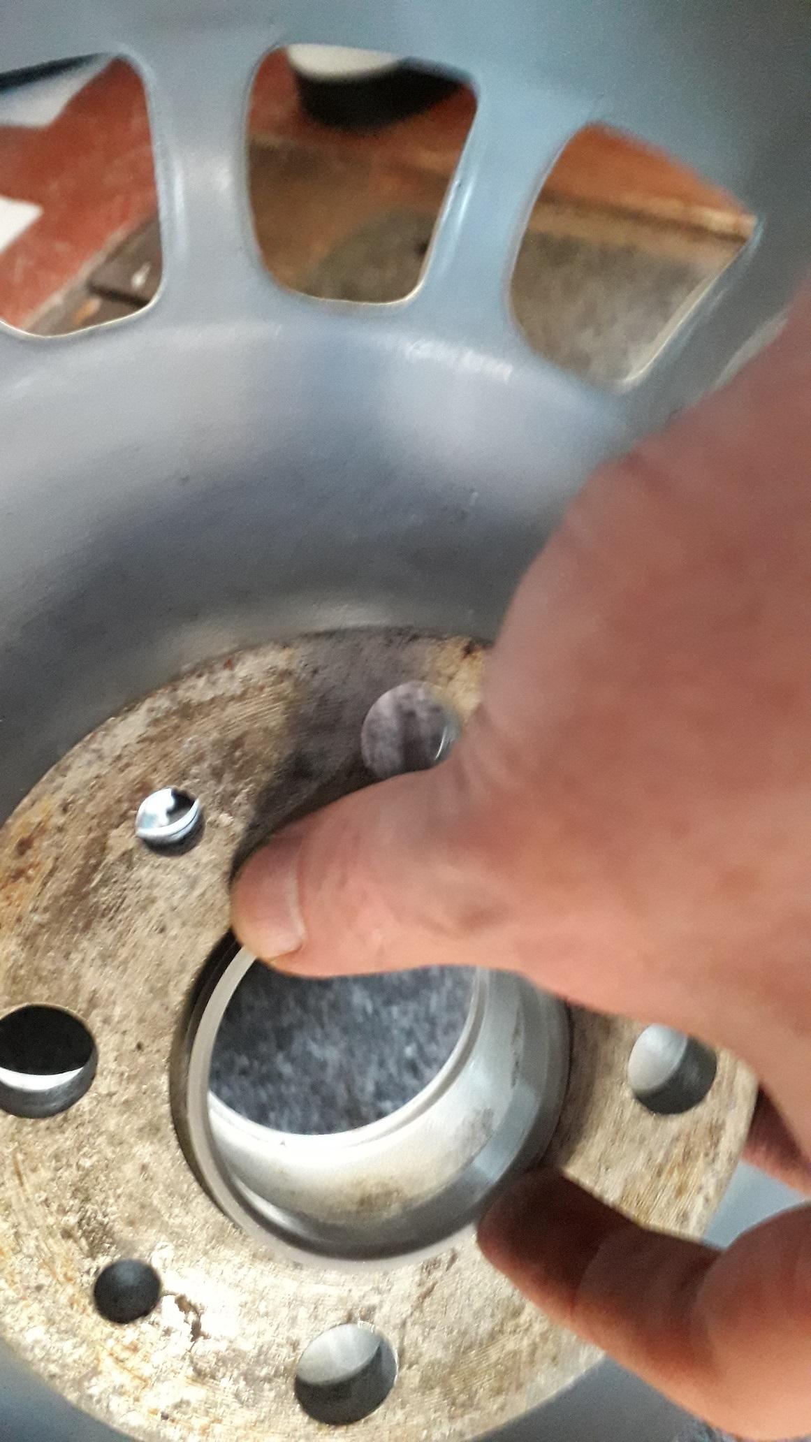
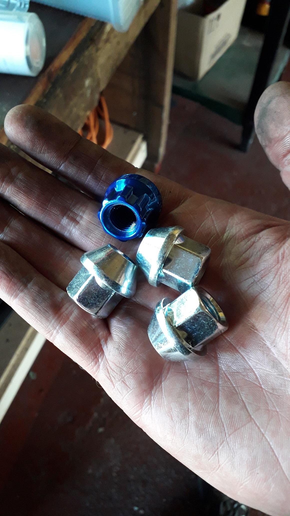
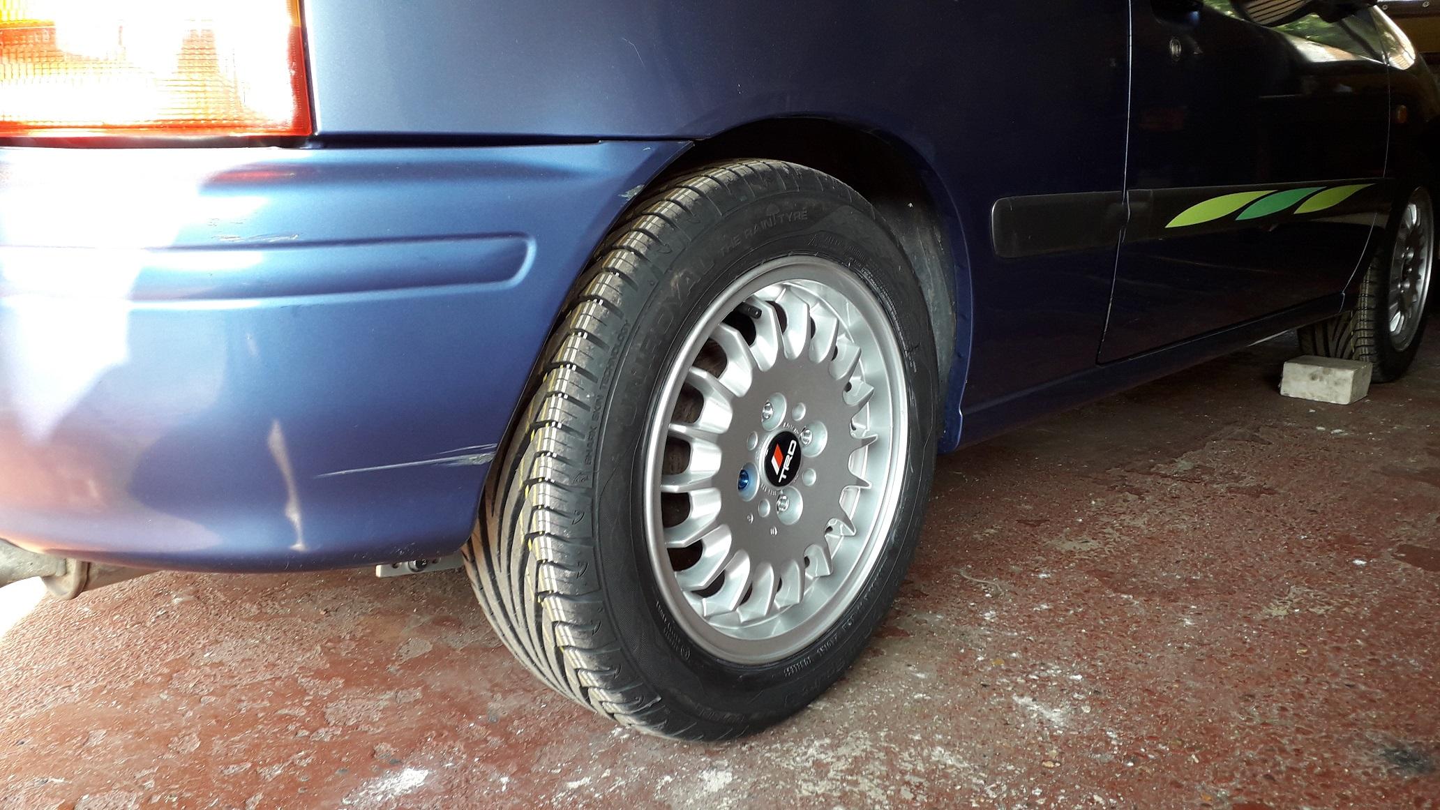
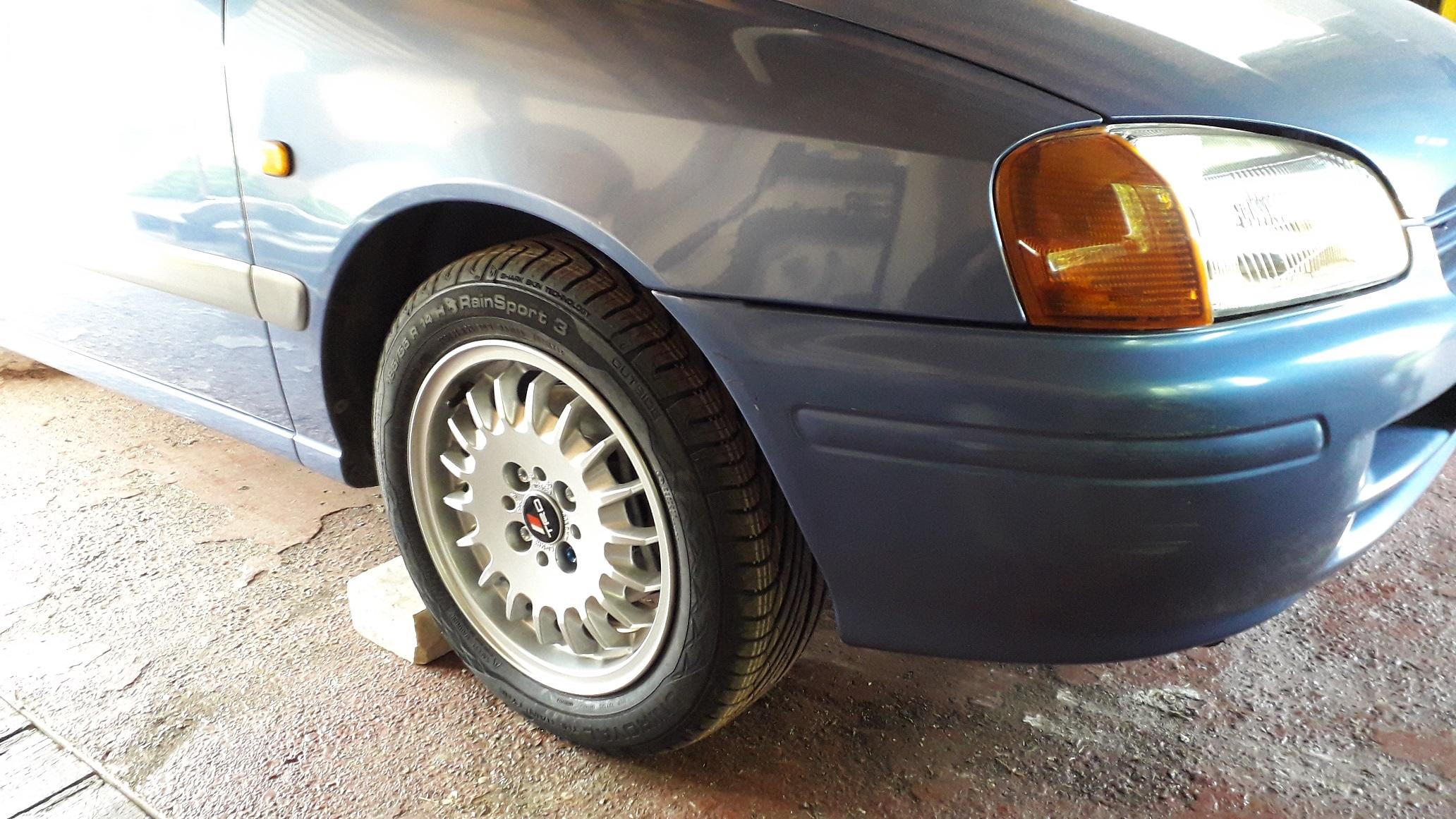
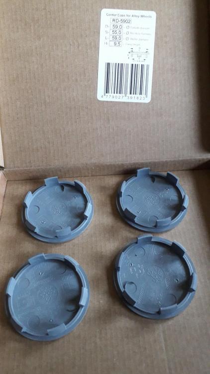
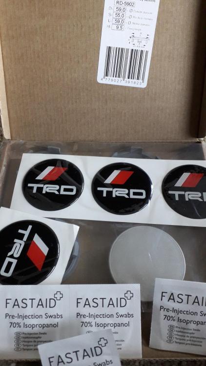
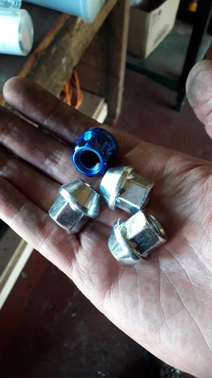
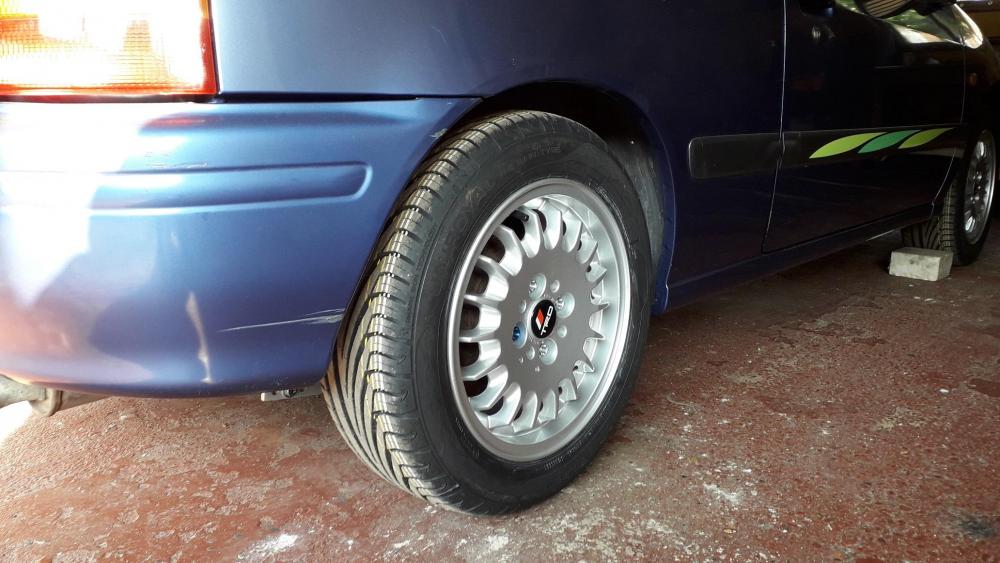
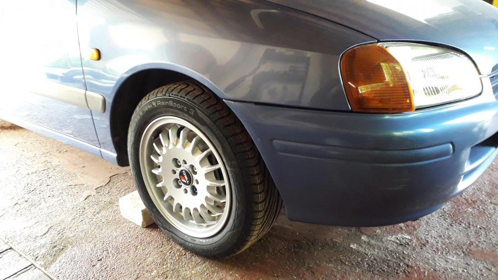
With the suspensions and brakes near enough complete it was time to find some alloys and tyres. Decided on 4 x 100, 14" x 6" rims (ET35). They're E30 "bottletop" rims. I've always liked them as they remind me of the Ronal Turbo's / Tom's racing wheels and only cost £120 for the 4. They're in excellent condition and looks like 2 of them were in the boot well for all their life! Fitted them with brand new 185 55 r14 Uniroyal rainsport 3's. Needed some centre caps to protect the hubs / driveshaft threads from puddles etc. Also decided that some TRD badges would add the finishing touch. Found them on eBay and they even came with some IPA wipes to clean the caps prior to adhesion. Ready to fit The centre bore is 57.1 and the Starlet requires 54.1 so I also added some spigot rings as well. New nuts required, the alloys are a 60deg conical taper seat, and the access holes are quite small so went for the 17mm hex version from drift works. Any larger and the socket doesn't fit. Thread is m12 x 1.5. All fitted up easily, cleared the stock and Glanza brakes. Took her out for a drive in the sunshine we've been blessed with recently and am very happy with the mods so far. Handling greatly improved, brakes much more responsive and no rubbing even with the 45mm drop and cut down rear bump stops. Didn't help that the old tyres were a mismatch of brands, part worns and only 145 wide! Suspension has settled approx. 5mm since I first fitted it, really like where its at currently. Just needs about double the power now.....🤔


-
Think the 370's would be out of duty for your purposes. Sucks about the injectors you've lost, I've got a set of 295cc fte injectors that I'm dreading sending off for cleaning in case they're stuck solid!
-
I had a quick check on some of the on line fuel injector calculators from deatschwerks and fuel injector clinic and at 80% duty cycle for 290 bhp it showed that 500 to 600 cc injectors were required! Seems high to me. Depends on the BSFC number they use for their definition of "turbocharged" though. The lower the base fuel pressure, duty cycle allowed and the worse the bsfc the bigger the injector size required. It says the 370cc is good for 188bhp at the crank?!? (3 bar fp and 80% dc) 255lph pump should be good for 500bhp apparently. I'm sure someone with actual experience will be able to comment. Seem to remember reading the 430cc's were ok to 300 bhp.
-
5EFHE, should seller be sectioned?
Claymore replied to Trevstar's topic in eBay, BidJDM, Yahoo Auction Finds
Looks like matey boy has busted a friend out of the asylum! 🤪 https://www.ebay.co.uk/itm/Toyota-Starlet-Gt-Turbo-Front-And-Rear-Fishnet-JDM-Very-Rare-Seats/164397243374?hash=item2646d6dbee:g:LKYAAOSwcKZfav5- It does say offers though.... -
Bargain fuel rail for those willing to travel!
Claymore replied to Claymore's topic in eBay, BidJDM, Yahoo Auction Finds
I know mate its ridiculous! He's too busy to post but can wait in for your courier to come and pick it up? Some people really can't be arsed, it is a real shame.