Claymore
-
Posts
660 -
Joined
-
Last visited
Content Type
Profiles
Forums
Wiki
Media Demo
Events
Everything posted by Claymore
-
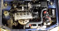
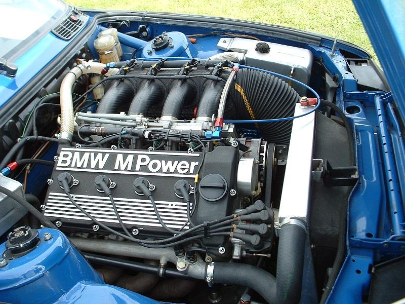
Just because it made me smile really The channel has some other interesting vids to do with bell mouth shape and design also. Last pic of my favourite itb intake manifold. 50mm slide throttles, carbon fibre 8 injector airbox from Tim Harvey's Labatts M3
-
Fair enough on the FPR, I presumed you'd be going with a piggyback to sort the fuelling side of things. This guy has done a pretty good write up of it. He couldn't get the fuelling right with adj. FPR and needed piggyback (hence my presumption). Don't forget the wideband o2 for tuning purposes. Looking forward to the progress
-
Dynoooooooooooooooo!😝 Sounds obvious but we'd all be interested to finally nail down what mods are producing the best gains. Which 4-2-1 manifold did you get? I've heard of the corolla cast one and the OBX for the 5e being converted to fit before. Again there's no dyno before and afters to show the differences. Not sure the fuel pressure regulator will improve much on an N/A unless the current one is a bit tired. I've seen some results posted with a corolla intake and throttle body, stock cam, 2" straight though exhaust. Made 86.6hp. Deleting the cat as you know is an MOT failure and swapping it out after the test will make the car "unroadworthy" in the eyes of the law so void insurance too. Universal fitment sport cats (200 or 100 cell) are available. From the other mods people have done it seem that the corolla manifold is a good, cheap, easy gain for N/A. Itb's are more suited to higher revving engines than the stock 4efe, shortening the inlet track significantly will most likely lose low down torque. Hopefully the improved breathing from the cam and an increase in redline will help. There have been a couple of ITB builds on here but unfortunately there haven't been any dyno graphs posted to show the improvements gained. It's best to mount the bodies as close to the head as practical to improve response and then play with different trumpet lengths to suit. All I can say for sure is that N/A tuning is a minefield and some mods improve and some will harm performance depending on the rest of the setup so testing and tuning is most important. Very interested to see the results.
-
Thanks, the parts bin raiding opportunities are what drew me to the starlet along with the aftermarket products available. Seems to be well covered from "mild" to "wild" builds. The hardest part is to cover all bases with track behaviour and then trying to have a docile "freindly" street car to drive for the rest of the time. Compromises sometimes need to be made. Hopefully the heavier pulley may just take the edge off and make the street behaviour acceptable for you. It is easy and cheap to try anyway. I do like the idea of using the corolla crank trigger and dizzy less system. Toyota O.E. development FTW. I had heard of the differences in cranks from 4e and 4et, I also read that someone had disassembled a late 4efe engine and it came with a 4et crank?! Could be internet BS but you never know.
-
I remember recently seeing a modern F1 driver describing his drive in a turbo era F1 car (presumably without als) and the technique of heel and toe throttle actuation on braking and turn in to keep the revs high for spooling the truck sized turbo ready for corner exit! Sounded like quite a handful. I take it you're already using the 4efte crank pulley? As you know this is heavier and would add mass to the rotating assembly. Might help bring some of the missing mass back.
-
Claymore's sleeper 4efe+t-t+t build (R.I.P. the Nanza)
Claymore replied to Claymore's topic in EP91 Progress Blogs
Spot on. Same for me with certain cars. 👍 -
I pretty sure the stock O2 sensor is before the cat and the temp. sensor is after the cat on the stock 4efte setup. Most forum search results say when fitting an aftermarket downpipe they remove the temp. sensor as its for cat warm up efficiency and no aftermarket downpipes have the fitting anyway, probably best to let TD guide you on that one. I would deffo recommend a wideband o2 sensor and gauge on any tuned car as a failsafe atleast. If the fuel pump gets tired or the fpr starts to fail at least you have a gauge on the dash telling you what the air fuel ratios are to help prevent engine damage from leaning out. Not sure how the wolf works but modern standalone ecu's should be able use the wideband data for all sorts of stuff. Closed loop fuelling corrections, targeting afr's etc. Don't forget to report back on how it goes, never seen any results from a wolf mapped glanza before.
-
No hard feelings Sam, I was trying to understand the system (as you said without the full description / info) hence my questions basically trying to help on points I thought you may have missed. Looking forward to the results, bit of F1 nostalgia making a comeback. .
-
I didn't realise the throttle would be partly open, this would allow air into the turbo to build boost. I have no idea about the amount of negative pressure, hadn't got that far. Nope, not my engine setup Think so. It's nice to see something different and was trying to get my head round it. I'm excited to see the results Sam. Keep us posted.
-
I was joking about making copies of the exhaust Sam! I'm still getting my head round the proposed layout but I'm pretty sure that I've read the oil seals in the turbo need changing for running in a vacuum or the oil will be drawn past them into the compressor housing and engine? Maybe I'm missing something but when the pre turbo throttle body is closed creating a vacuum from throttle plate to manifold throttle plate (to maintain turbo spool), it also prevents air being drawn into the compressor so it can't produce any boost? The pre turbo throttle is opened by boost pressure to a hks turbo actuator operating the pre turbo throttle body but it won't see boost because the turbo can't produce any so it won't open again? Dunno but you've given me a puzzle to think about again. Edit: Forgot to say, with the six speed box and final drive ratios you should be experiencing less rpm drop between shifts also? So shifting up at 6000 rpm drops you down to perhaps 4800 rpm and the turbo should still be well on song at that point with a decent dump valve and responsive external wastegate setup and modern EBC? Does the als only really provide benefits at low rpm acceleration as the boost potential from the fully spooled up turbo is available there?
-
Claymore's sleeper 4efe+t-t+t build (R.I.P. the Nanza)
Claymore replied to Claymore's topic in EP91 Progress Blogs
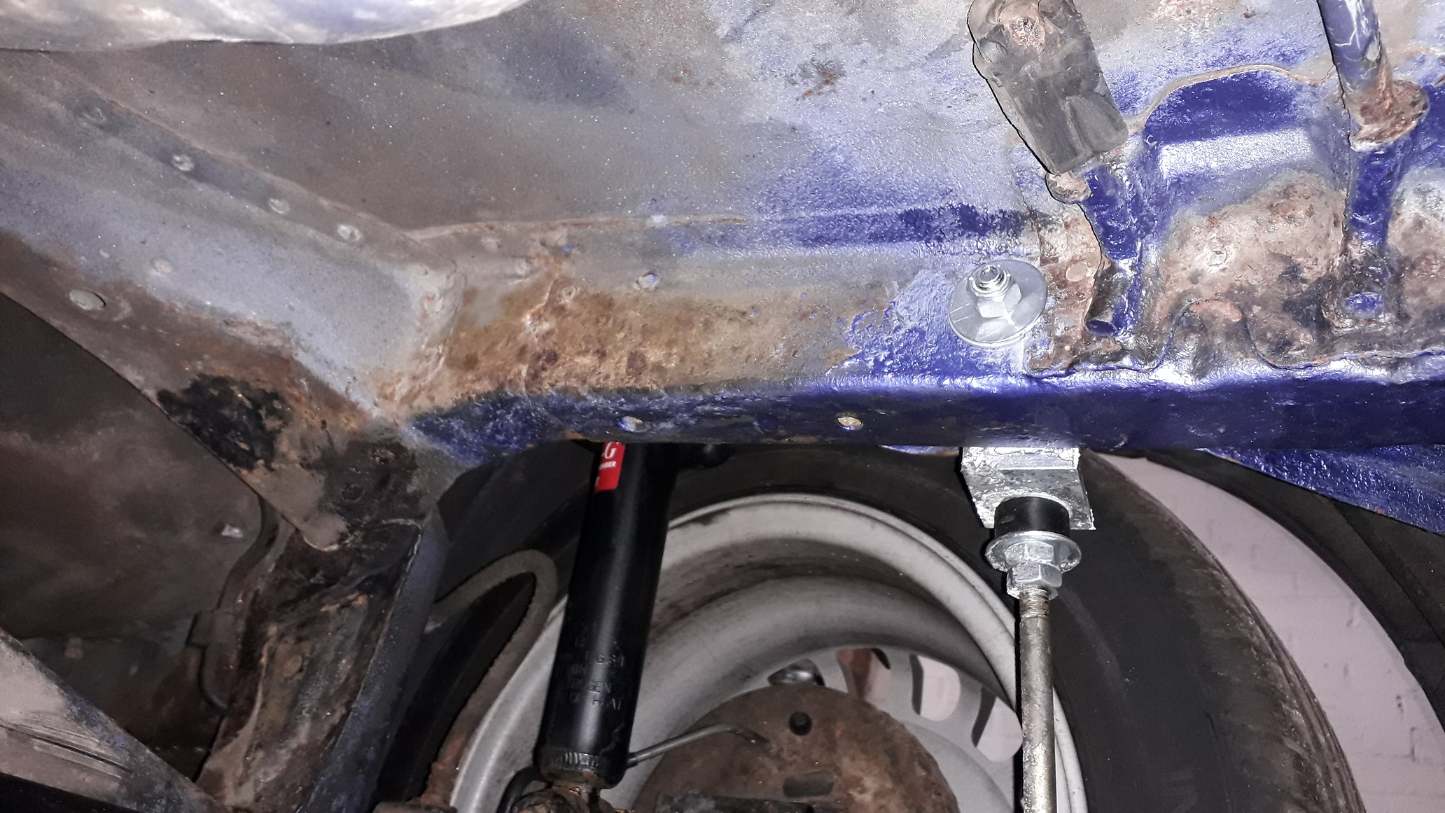
Thanks mate. For me the decision was easier! I care about all the cars I've owned (some more than others) but this one was only £850 and I was happy to drill it. If you look at the picture below (seems familiar?) you have already discovered the exhaust reinforcement bracket on the drivers side that I was noting above. As your glanza is one of the cleanest I've seen for a while I don't know if I'd recommend drilling holes in that beautifully clean chassis! I understand it's your car and you can of course do what you want to it, but in the future cars of your level of cleanness will command a price premium. I hate seeing cars as investments but sometimes it can't be ignored. There are alternative arb's like the ultra racing. They're non adjustable but are available in 2 different thickness's. They look to attach to the beam the same way but the arms point forwards and look to pick up on existing chassis points. http://ultraracing.my/ecatalog/index.php/product/toyota-starlet-ep-91-rear-anti-roll-bar-rear-sway-bar-rear-stabilizer-bar-2/ I've not fitted one of the ultra racings and cant seem to find the instructions to confirm this so I'm only going off the photo! Might be an option for you to investigate. I wish all companies made the instructions available on their website. *EDIT* Found a rear photo of the arb drop link mounting bracket installed. Rust repairs immanent!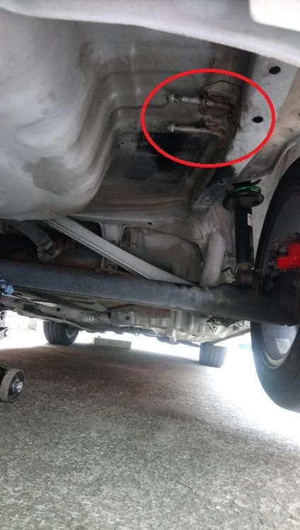

-
Looks like some good progress, interesting with the pre turbo throttle body. I take it this is in addition to the normal throttle body? Going to be used for 80's F1 style anti lag system? Is this still the 4e or have you built your 5e up yet? Also if you've got a jig for the manifolds how about making some copies!?
-
Super clean underneath too 👍
-
5EFHE, should seller be sectioned?
Claymore replied to Trevstar's topic in eBay, BidJDM, Yahoo Auction Finds
Nurse! He's out of bed again! 🤪 https://www.ebay.co.uk/itm/TOYOTA-SERA-5E-FHE-ENGINE-CRANK-SHAFT-4E-5E-FTE-STARLET-GLANZA-V-TURBO/203078813102?hash=item2f4870c5ae:g:YiMAAOSwRUNfOU18 At least its got offers on it! £50? Lol 🤣 -
Claymore's sleeper 4efe+t-t+t build (R.I.P. the Nanza)
Claymore replied to Claymore's topic in EP91 Progress Blogs
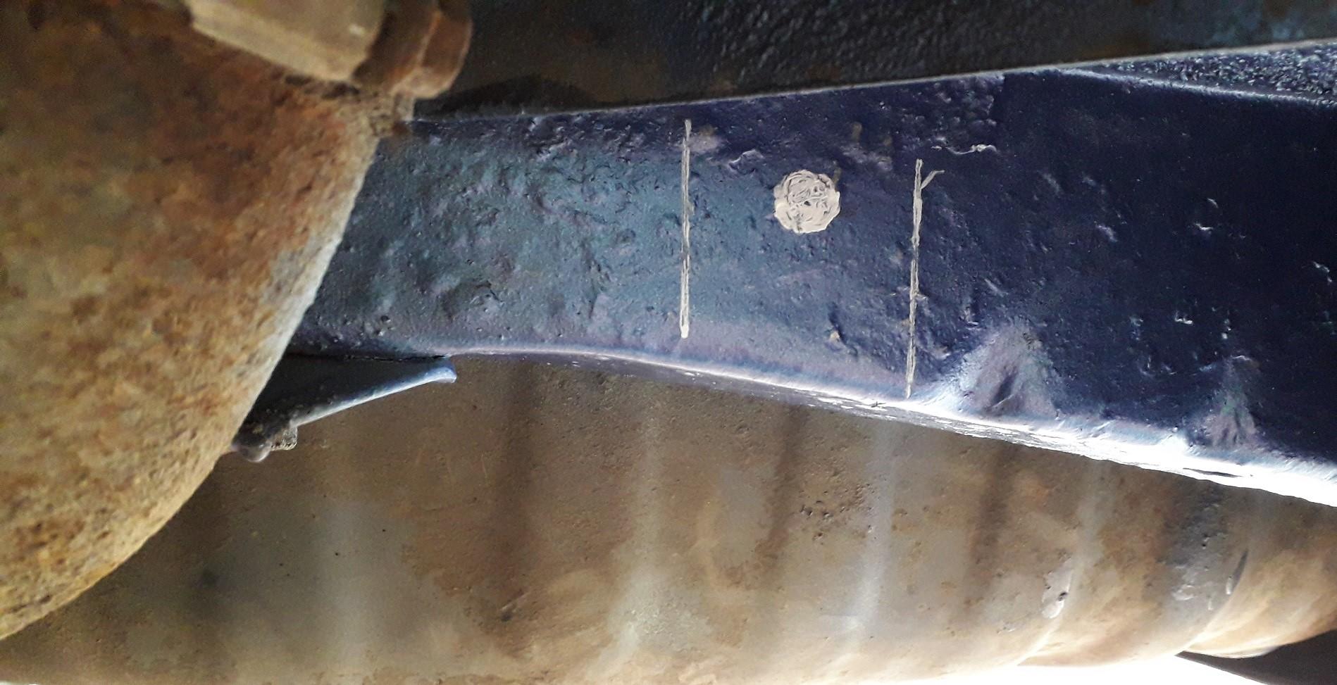
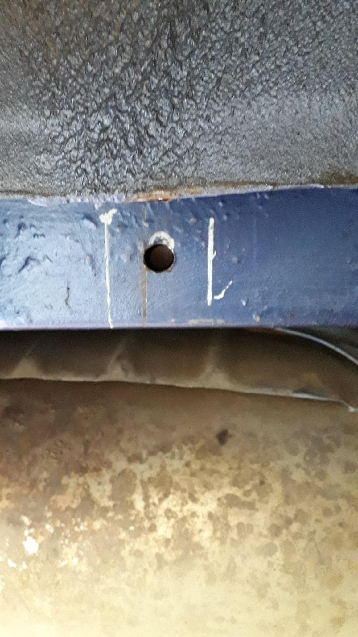
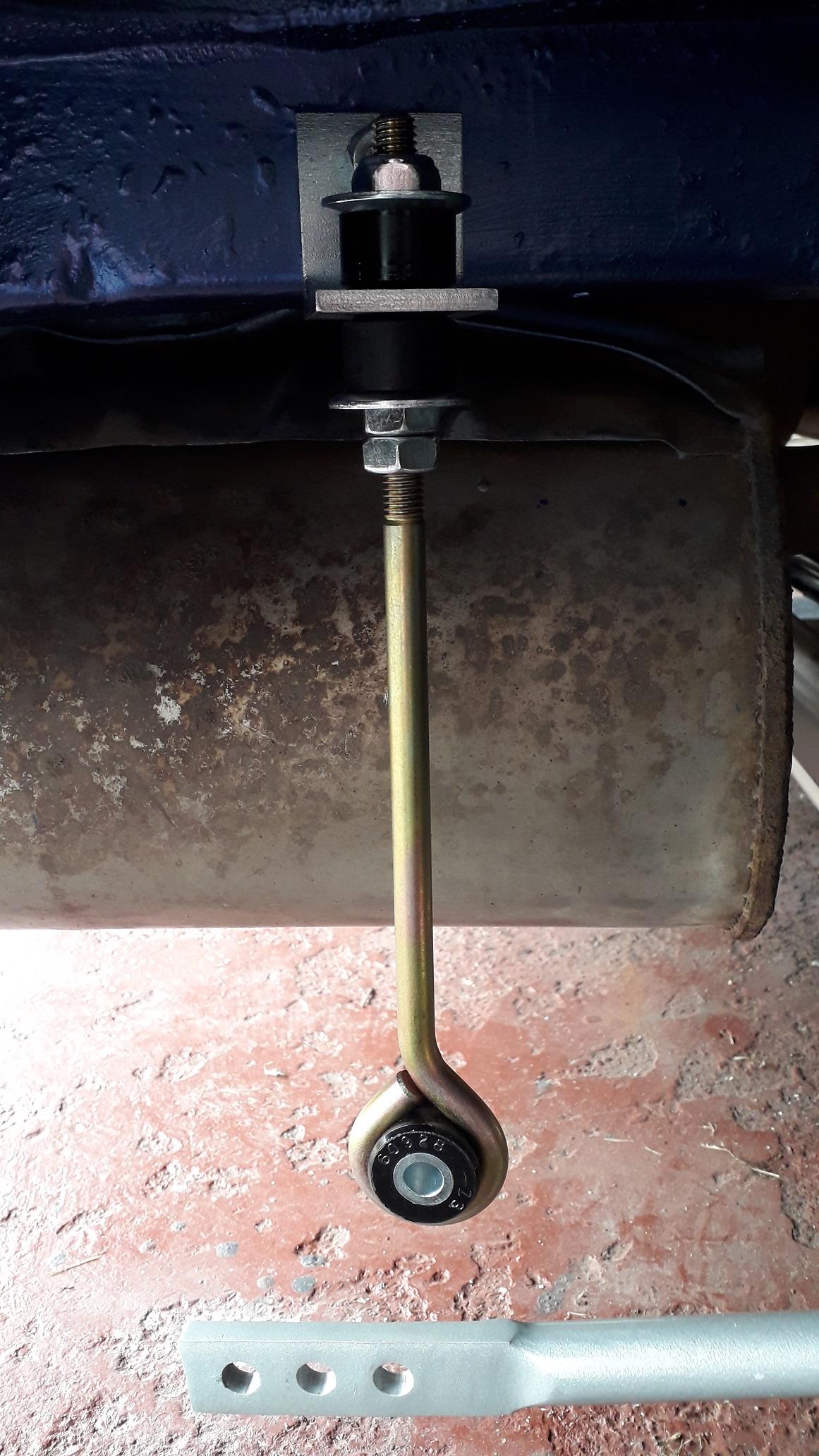
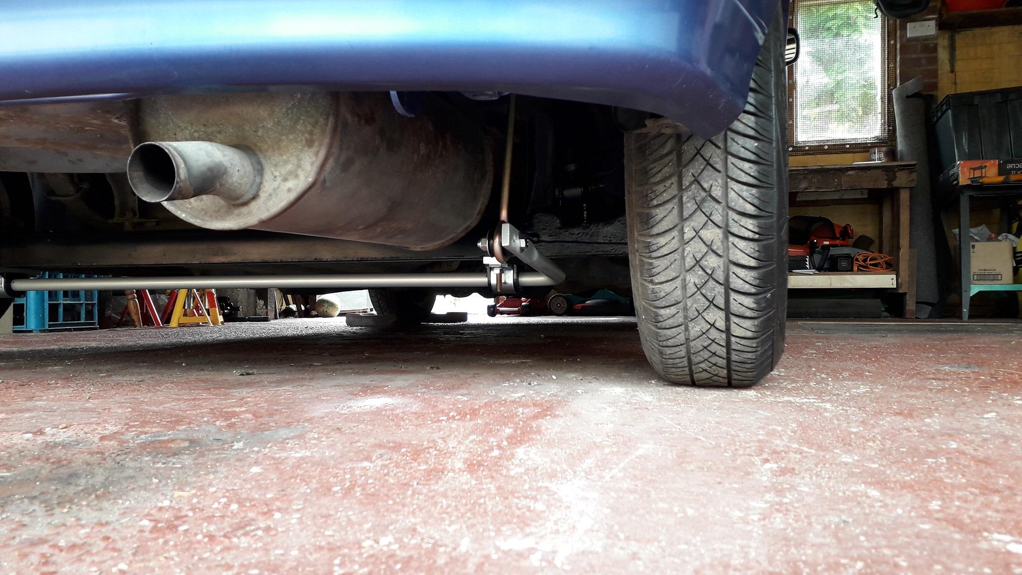
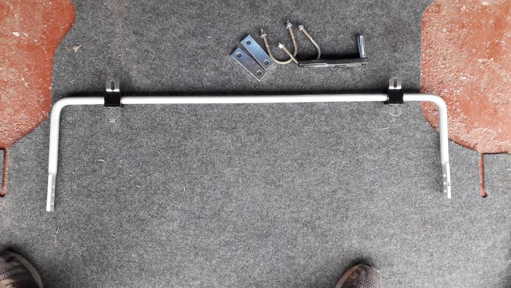
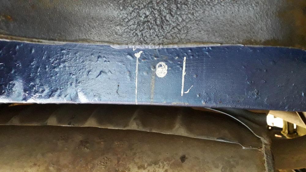
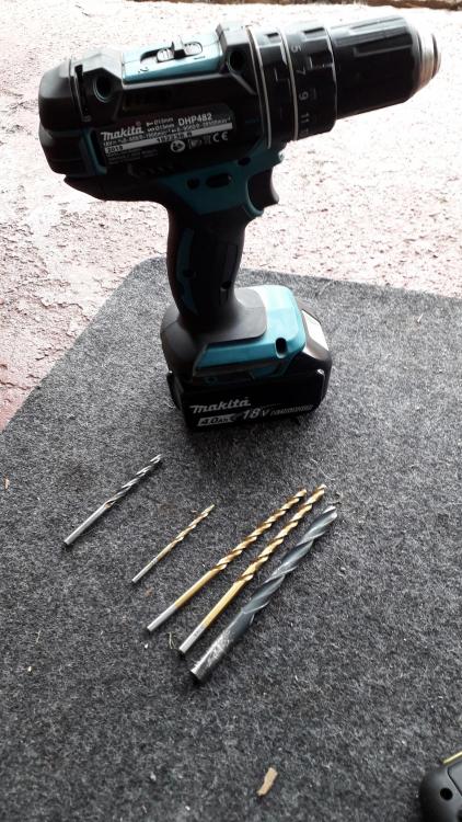
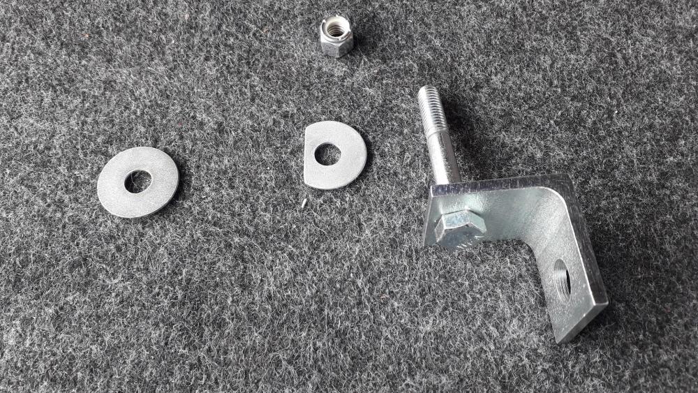
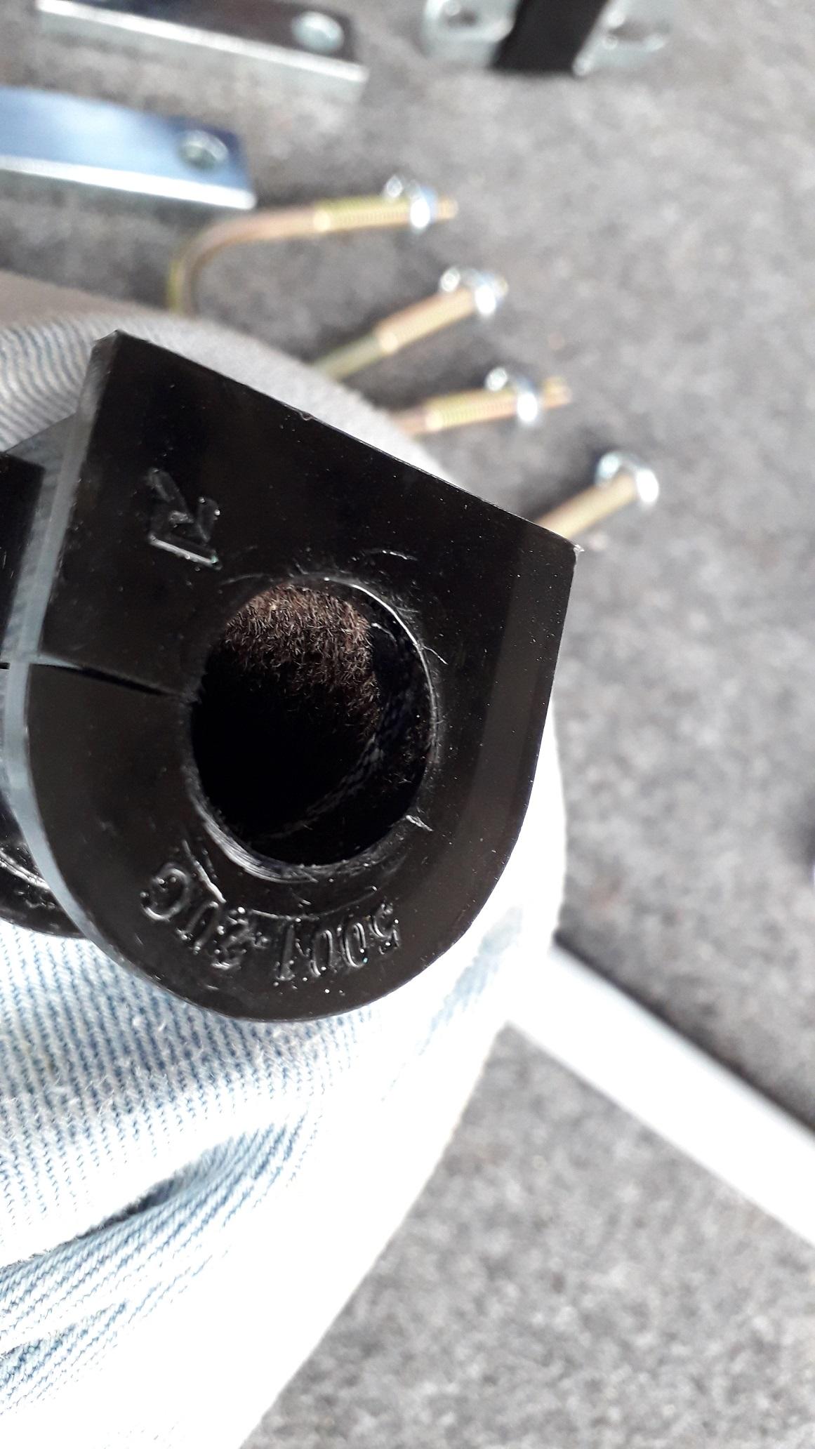
Whiteline adjustable rear anti roll bar install: Vehicle was safely set at ride height and the wheels removed. First I assembled the D-bushes to the anti roll bar (arb). They are a new design that is "grease free" having a PTFE fur lining. Stops the need for grease which can attract grit and wear the bushes out faster. Metal saddle clamps pressed over bushes, I marked the centre of the bar and the centre of the rear beam. Installed the arb centrally with the U-bolts over the beam, through the metal clamp blocks to attach through the saddle clamps with 2 x shakeproof flange nuts. I then attached the arb drop links to the central hole on the arb arms with the chassis brackets attached to the top. Rotated the drop links into the most vertical position on the chassis rails I could and marked the position of the mounting hole and the bracket sides in white paint pen. I then tried to insert the drill and found I would need to lower the hole to allow the chuck access. A word of caution: on the drivers side behind the rail is a reinforcement plate which is used to attach the exhaust mounting bracket. I transferred this line to the outside face in pencil to know how far back the hole could be drilled. Any further back would have been a real mess to mount the nut and washer. The passenger side is clear and the drop link can mount vertically, the drivers side is slightly angled forwards. Passenger side position With everything measured and checked it was time to drill the bastard! Centre punched the holes, and started out with a short 5mm bit, then a long 5 x 132mm bit to make it through the box section and opened this out with a 6 x 139mm drill bit finally followed by a 10 x 139mm bit. Light pressure forwards but firm grip to reduce chattering. Long drill bits and small chuck / drill body are essential as space is very limited. Make sure you drill straight and flat. Holes drilled, zinc primed and then top coated. On the drivers side I made a D- shaped washer to fit on the rear face next to the exhaust bracket to bring it all to the same level as the exhaust bracket. Then I attached the large washer and nut to fasten the chassis brackets. Brackets mounted both sides. Don't over tighten as the metal sections are quite soft. Drop links attached, again don't over tighten as the rubbers are soft. I set the length so the arb arms were close to horizontal but slightly higher at the adjustment hole end. Then attached the drop links to the central hole using the bolt, 2 x washers and nylon lock nut provided. All done, wheels on and back on the ground. All in all a good product. Will improve handling and is adjustable to suit different suspension setups, cheap and relatively easy to fit. The down sides are for a road car you lose 50mm of ground clearance. Can't jack up the car under the rear beam anymore. If I was doing it again I would probably look into welding the chassis brackets to the chassis rails instead of bolting as this would allow free placement on the drivers side. Also the rear face of the passenger chassis rail is angled so the nut doesn't sit flat. Not a problem just looks weird, might "dress" the area flat if it bothers me in the future. Please with how it came out.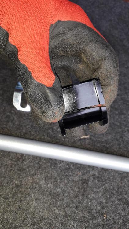

.thumb.jpg.274eb228f4f566dd0b1a38333b6cf4d4.jpg)


-
Good times 😎👍
-
Thanks for the comment. Don't need the valve springs though. Cheers
-
Very neat. I like it.👍
-
Bought a GT thermostat housing. As described, good price and fast delivery.
-
+2 from me. Bought a couple of things, both arrived as described in good time.
-
Claymore's sleeper 4efe+t-t+t build (R.I.P. the Nanza)
Claymore replied to Claymore's topic in EP91 Progress Blogs
Thankfully I can PM the admin team and they're looking into it. -
Claymore's sleeper 4efe+t-t+t build (R.I.P. the Nanza)
Claymore replied to Claymore's topic in EP91 Progress Blogs
Thanks mate, Think I've verified my email, I can send PM's to some members but not others. I'll try yours. Edit: Nope! -
Claymore's sleeper 4efe+t-t+t build (R.I.P. the Nanza)
Claymore replied to Claymore's topic in EP91 Progress Blogs
I guess that why they offer higher pressure rad caps like 1.2 bar etc. It looks from your description of the system that I understand the coolant flow when hot and cold. My only concern was that in swapping the hoses at the thermostat this reverses the flow through the radiator when the system is up to temp. The top hose thermo housing outlet is now attached to the bottom hose feeding hot coolant into the bottom rad tank and the bottom hose thermo housing inlet is now attached to the top of the rad. The coolant flows from bottom to top now, I think I'll leave it as Toyota intended. -
That's weird? when I unplug my icv connector when warmed up it raises the idle! As far as I know the valve defaults to an open position which raises idle rather than oscillating the valve. Is it the icv from the new replacement engine? maybe its stuck and not adjusting with the coolant heat. Do you have the old icv from the original engine you could try?
-
Claymore's sleeper 4efe+t-t+t build (R.I.P. the Nanza)
Claymore replied to Claymore's topic in EP91 Progress Blogs
I would have thought the overflow bottle would have been ok at containing the expanded coolant escaping from the radiator through the cap or I fail to see the function of the bottle at all?! Also if I understand correctly the coolant flows from the block to the back of the thermo housing, through the bypass hole and back down the tube behind the engine to the water pump and then into the engine. The coolant heats up, opening the thermostat and closing the bypass hole (or slowly fluctuating to increase flow through the radiator.). So coolant now flows from the block to the back of the thermo housing, through the top hose (as bypass is closed), to radiator and out the bottom hose back into the side of the thermo housing through the newly opened thermostat and back into the engine via the tube behind the block to the water pump when warm. If you swap the hoses at the thermo housing won't you be filling the radiator from the bottom now? With water exiting the top of the rad? Not sure the pump has the power for that. Also does it not increase the risk of air being trapped in the system? By all means give it a try and report back, you seem to be the forums resident mad inventor! lol😃 The way I look at it more mods = more potential issues. Minimal changes to get the best acceptable outcome. Keep it simple ......


.jpg.02983778a8713abdf5b328772753c07a.jpg)