Claymore
-
Posts
660 -
Joined
-
Last visited
Content Type
Profiles
Forums
Wiki
Media Demo
Events
Everything posted by Claymore
-
Claymore's sleeper 4efe+t-t+t build (R.I.P. the Nanza)
Claymore replied to Claymore's topic in EP91 Progress Blogs
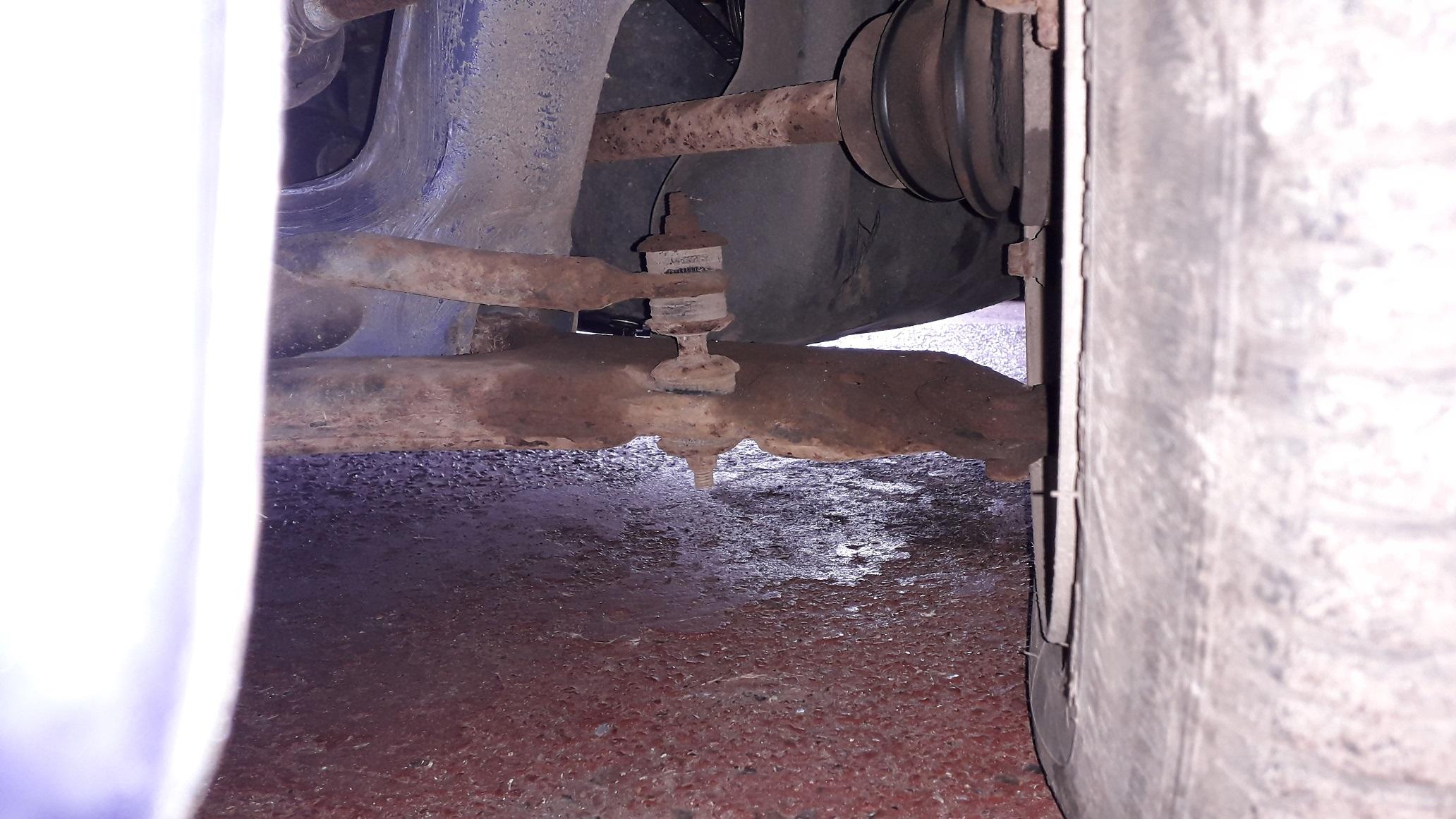
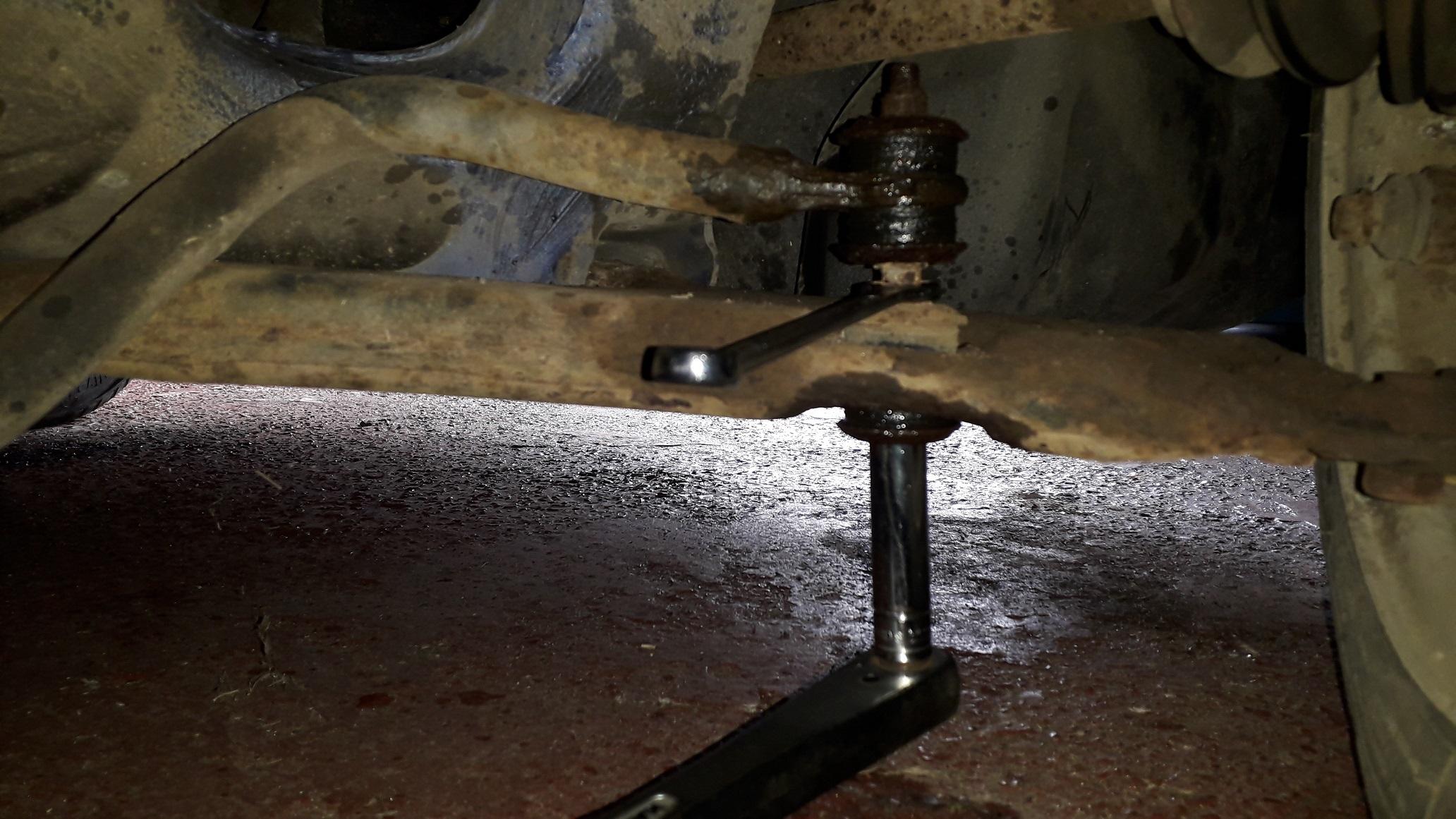
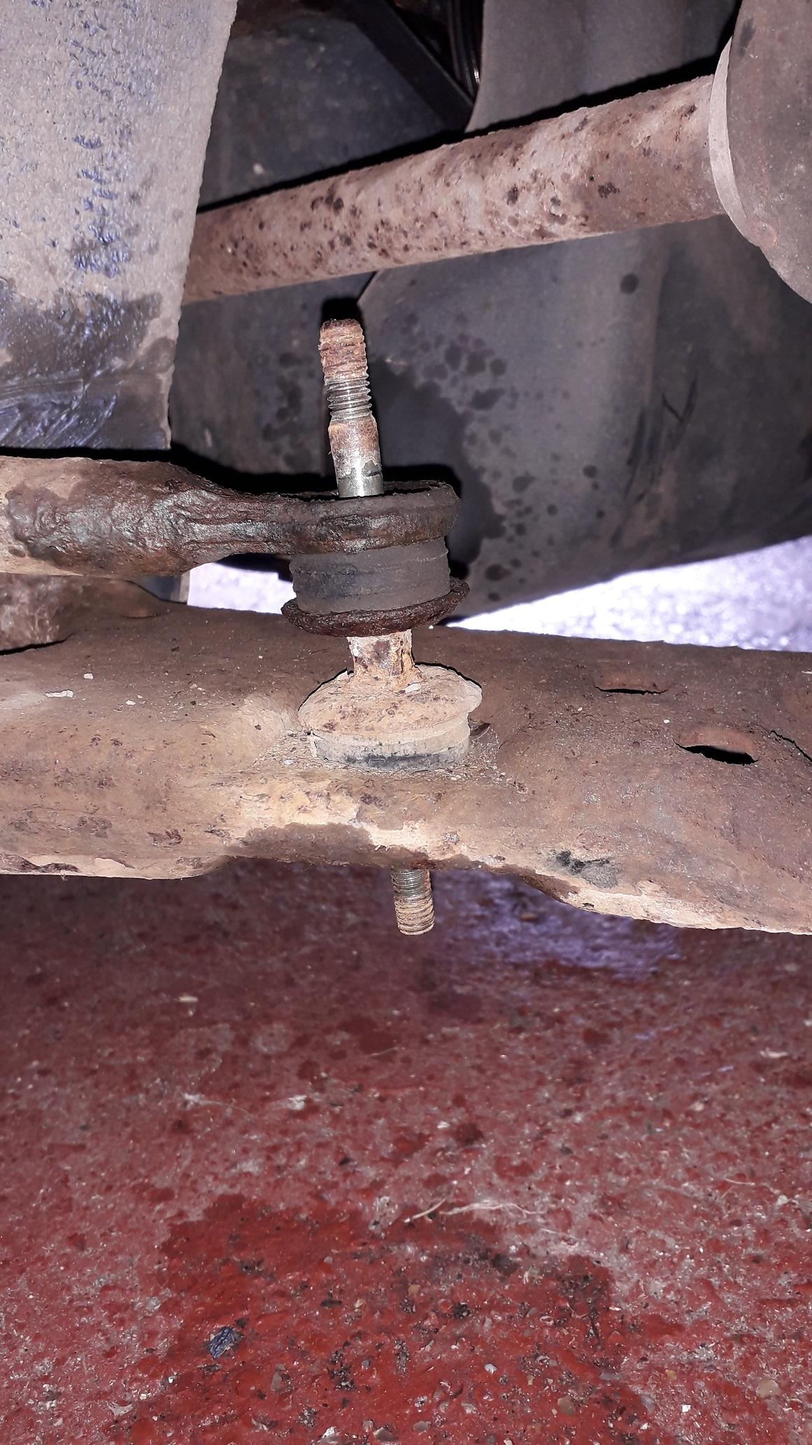
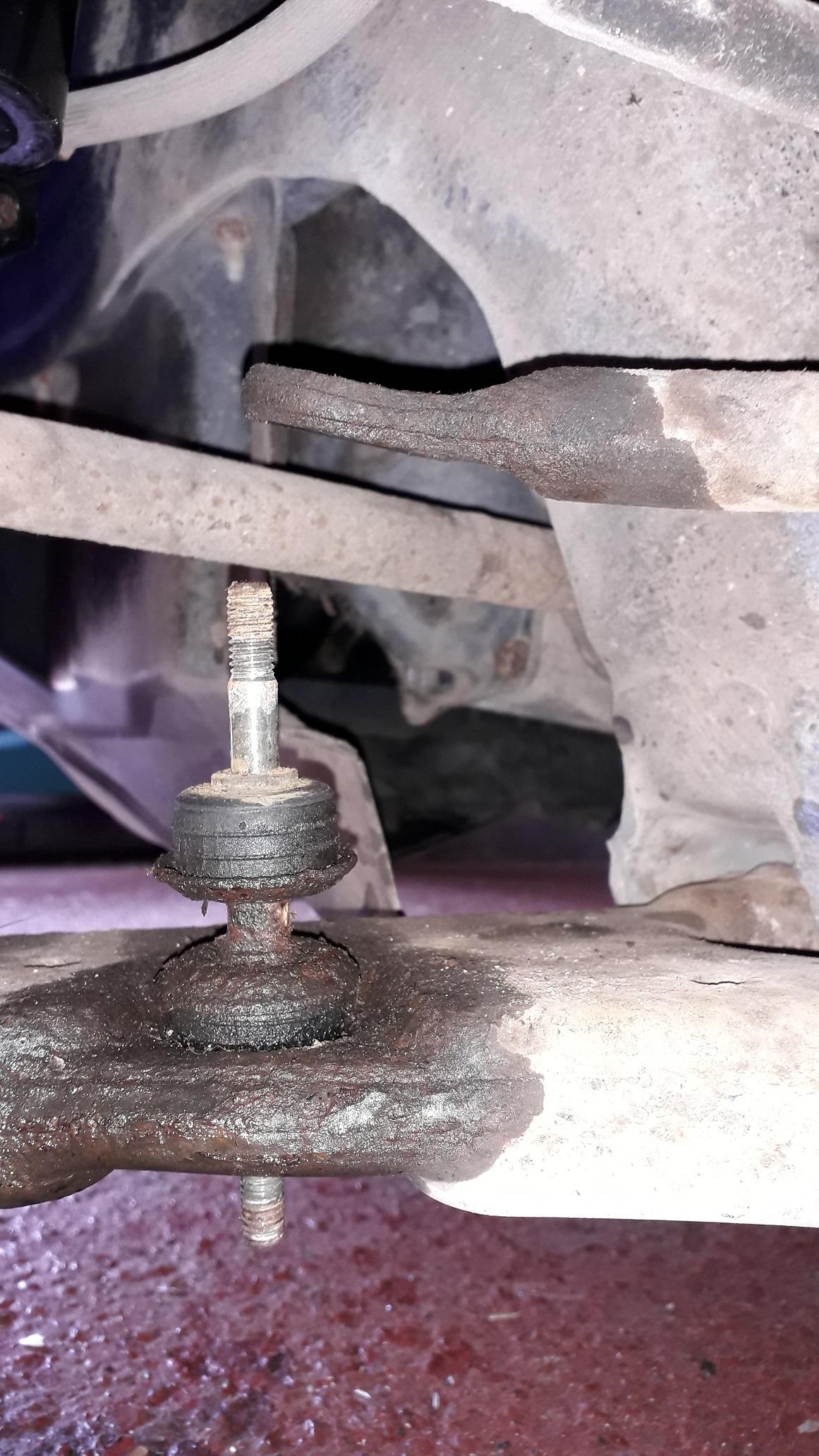
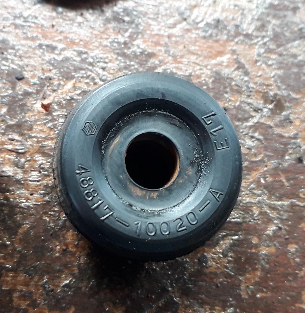
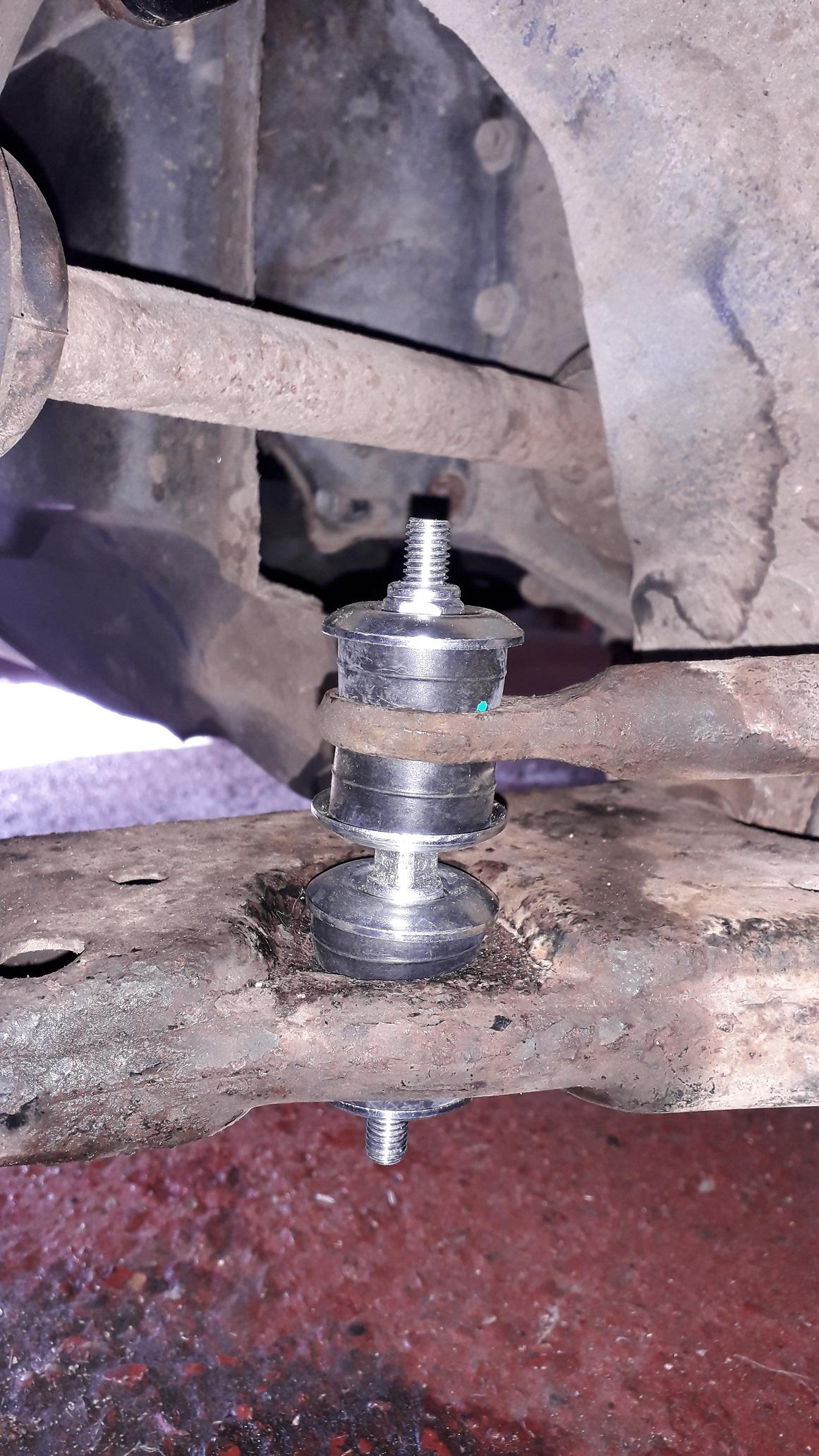
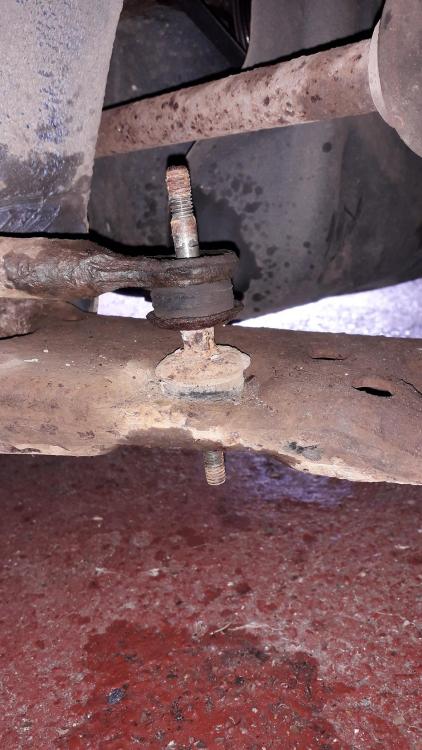
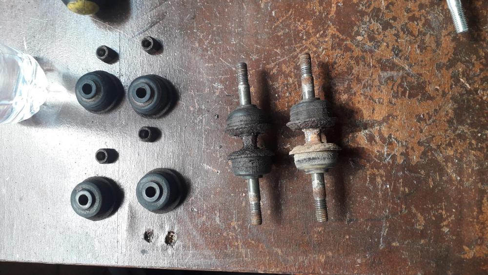
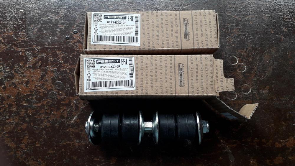
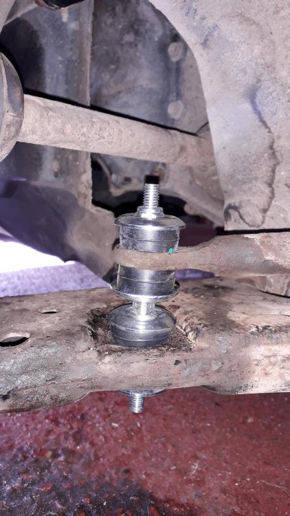
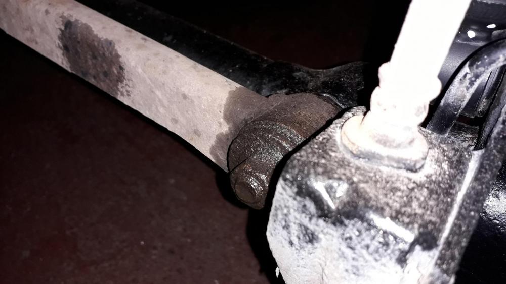
A quick update before the rear anti roll bar. Front anti roll bar drop link replacement: The rubber bushes were looking a bit worse for wear and the amount of corrosion on the screw threads was getting to the point were removal would have been difficult in the future. Soaked in WD-40 to help loosen and reduce friction, the threads were accessible so plan b was to clean up the exposed threads with a die to help removal (thankfully not required). 10mm spanner in the centre attached to the square section and 12mm deep socket to remove the nuts either end. Top and bottom nuts, cup washers and bushes removed both sides. Arb lifted to release the drop link. Old links removed, rubbers were a bit perished. Old bush part number 48817-10020. Toyota parts. Replacement drop links Febest 0123-EXZ10F. In all honesty, not the best quality, the threaded link is fine but the cup washers have a wider dish recess than the recess in the rubbers and 2 x rubbers weren't moulded 100% correctly. The nuts are also 13mm across flats hence the wider washer dish. Fitted the drop link to the wishbone first, making sure the shoulders of the bushes sit into the hole in the wishbone then loosely attach the lower bush, cup washer and nut. Repeated for other side. Push arb down over drop link (both sides) and add top bush making sure both bush shoulders are in the arb hole. Add cup washer and nut then tighten. The previous nuts were tightened to the bottom of the thread on the link and as the replacement components were the same length and thread length I copied this method. Thankfully after tightening all the nuts down, the washers compressed the bushes and the slight moulding issue didn't matter. Yes I forgot the copper grease but I think they'll be getting changed before it matters any way ! LOL 😆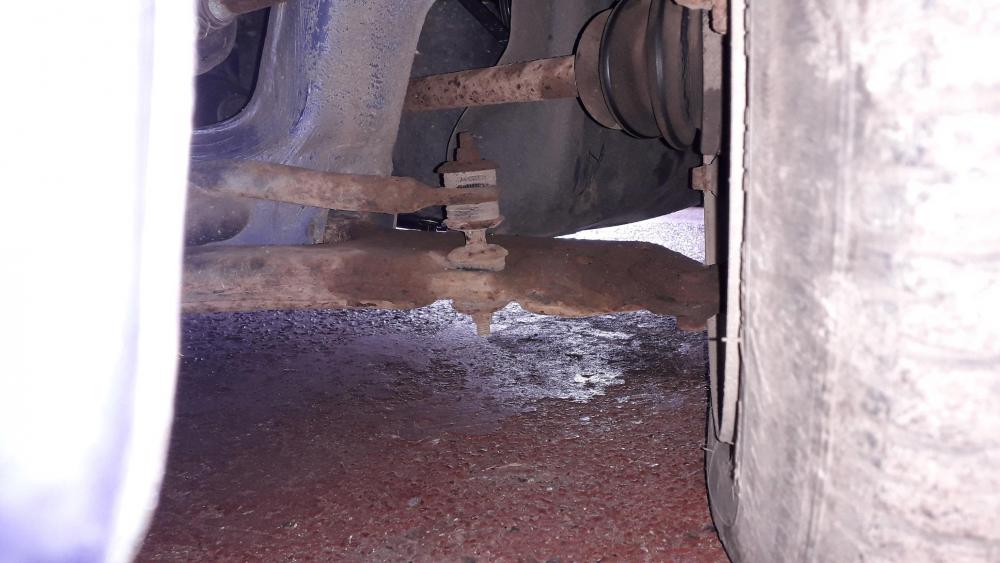


-
I think most of the possibilities have been covered above, check for leaks, make sure all the electrical connectors are plugged in. The idle control valve setting and throttle stop screw are set at the factory and should not need adjusting. Is the throttle cable too tight / sticking? if you unhook it from the throttle body does the idle change? If you unplug the idle control valve connector when the engine is warm does the idle change?
-
Claymore's sleeper 4efe+t-t+t build (R.I.P. the Nanza)
Claymore replied to Claymore's topic in EP91 Progress Blogs
I'm fine for turbo's thanks Sam, a genuine Tong's hybrid is a very sort after turbo. They'll be queuing up to buy that from you. I'm ok for other parts at the moment I think, got the power steering stuff already. I'll let you know if I think of anything. Yes I know what you mean, I was a bit shocked at how flexible they were whilst doing the rear suspension work with the panhard rod taken off. Pretty basic, old fashioned design really but not exactly a race car to start with. Can't wait to drive it again. 👍 -
Claymore's sleeper 4efe+t-t+t build (R.I.P. the Nanza)
Claymore replied to Claymore's topic in EP91 Progress Blogs
Payment sent, I've covered the postage and paypal fees. -
Claymore's sleeper 4efe+t-t+t build (R.I.P. the Nanza)
Claymore replied to Claymore's topic in EP91 Progress Blogs
Interesting on the bubbles thing, don't want boiling up in the turbo jacket. -
Claymore's sleeper 4efe+t-t+t build (R.I.P. the Nanza)
Claymore replied to Claymore's topic in EP91 Progress Blogs
Awesome, looks like the water channels go straight back one either side of the thermostat. -
Car feels like it’s running slow in heat
Claymore replied to _LM46's topic in 4E-FTE Engine Discussions
It can be many things, you've posted before about issues with idle speed and also having error codes relating to idle control and MAP sensor. Have these problems been fixed? Have you modified or changed anything recently? Firstly do a diagnostic check to see if there are any codes. Also check the obvious thing like boost pipes and vacuum hoses for damage / leaks / clamp tightness / intercooler damage / blocked air filter. When you say it "runs hotter" do you mean that the coolant temp. gauge moves above half way when driving hard? Also if you take the car for a drive early in the morning when the air is cold does it boost normally? -
4efte thermostat housing, where do the pipes join?
Claymore replied to Claymore's topic in 4E-FTE Engine Discussions
Cool Cool, I've contacted admin about the PM not working. I can also PM some people but not others, weird. I too have heard of people re wiring but I don't fancy cutting the loom unless I have to, or finding the glanza loom plug and pigtail to wire it. -
4efte thermostat housing, where do the pipes join?
Claymore replied to Claymore's topic in 4E-FTE Engine Discussions
Thanks Sam, PM me with photos and price please if you want to sell one of the spares, I've tried to PM you in the past but it doesn't work. Maybe you have that setting turned off? -
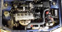
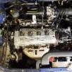
I'm still having no luck finding an early style 4efte thermostat housing (the one with two separate temp. sensors) for my 4efe + t build. Plan B is to possibly modify an existing 4efe unit by drilling and tapping to get the required feed and return for the turbo. Looking at an existing 4efe unit there appears to be the "sites" for this drilling to occur but I hope some one can confirm (with photos) where they join to inside the housing. Any help appreciated, photos, descriptions etc. or if anyone has an fte item for sale that would make my life a lot easier! Lol 😆
-
Claymore's sleeper 4efe+t-t+t build (R.I.P. the Nanza)
Claymore replied to Claymore's topic in EP91 Progress Blogs
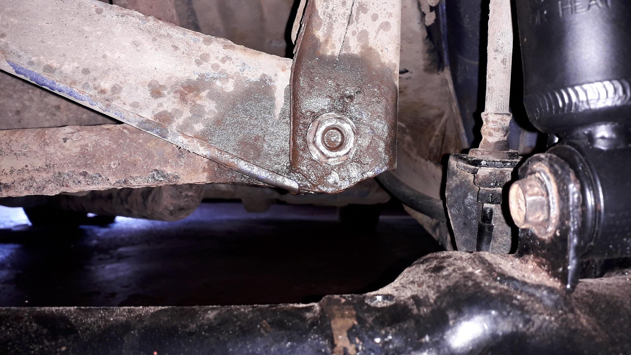
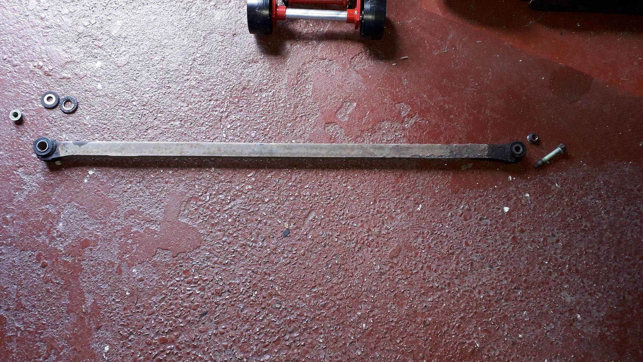
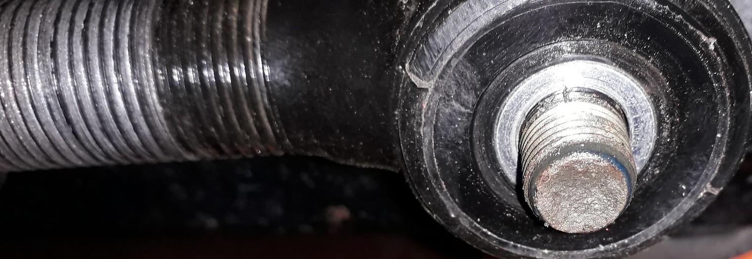
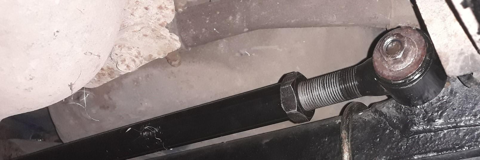
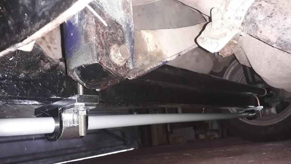
Whiteline adjustable panhard rod fitment. Since lowering the car (admittedly only 40mm all round) it's well known that the standard length panhard rod is only really suitable for stock ride height or it will push the rear beam out to one side as it is lowered to its new ride height. First I supported the rear of the car safely at ride height, removed the wheels for access, then removed the drivers side nut and bolt. Then I dropped the right hand end of the rod out of its mounting channel. Cleaned out the surface rust from the channel and treated with Hydrate 80. Secondly, removed the nut and large washer from the shouldered mounting stud on the passenger side and slid the rod forward to remove. Manky old rod removed, note there are two different style washers on the passenger side. The rubber bushes were ok condition but the steel rod had seen better days especially on the drivers side. So I copper greased the adjuster thread, set the whiteline rod at the same length as the original so I new what length it shouldn't be and fitted it to the car. Using a plumb weight and string from the outer arch I measured from the string to the brake drum face (both sides) to see how off the beam was. There was about 5mm difference so I dropped the rod out of the drivers side, adjusted the length and reinstalled, repeated this until I eventually got the measurements equal. Good enough until I can get an alignment done. Passenger side first, added large hole washer, greased the shoulder stud, added rod end, then the short tubular collar from the parts pack in the whiteline packaging, then small hole washer and flange nut (with medium threadlock). When I tightened the nut it presses the short collar into the bush (effectively lengthening the shoulder of the stud for the nut to clamp to without crushing the bush). Greased the faces of the bush, lifted the drivers side into the mounting channel and using an old screwdriver to wiggle the bush in line with the hole was then able to insert the bolt and tighten with the old flange nut (again with medium threadlock). Finally tightened the lock nut for the adjustable length screw once it was all in position. Also marked the nut and rod with a paint dot to see if it comes loose. Overall a good product for the price but by no means perfect. The thickness of the pass. side bush means that the securing nut is not able to thread fully onto the shouldered stud leaving it approx. 2 turns sub-flush (poor engineering practice). The drivers side originally clamps the channel to the metal tube bonded to the rubber bush, the new rod has the bush wider than the metal tube meaning it gets a bit squashed before you attain a reasonable tightness. No instructions provided, not that hard to figure out but still. Also the old whiteline design of rod had a nut welded to the end of the bar to use to tighten the locknut against, this has been replaced by 2 x flats pressed into the tube sides (cheaper manufacture). Don't get me wrong I'm still happy with the product but there have been savings made in the manufacture. Rear anti roll bar next.


-
Josh's forged 5E Massive spec forged build! 370BHP!!
Claymore replied to wakeabby14's topic in EP91 Glanza Progress Blogs
😎 -
5EFHE, should seller be sectioned?
Claymore replied to Trevstar's topic in eBay, BidJDM, Yahoo Auction Finds
That's the stuff I Pm'd you about, the 3 piston guy is also selling a block and no crank. Wonder what happened to that engine. All seem pretty pricey but rarity means people take the piss with prices. Might be worth searching for "Sera / Paseo breaking". Engines probably gone already though. It seems that as times are getting harder more people are selling up their hoarded goodies they're not using. So you never know what might turn up in the future. -
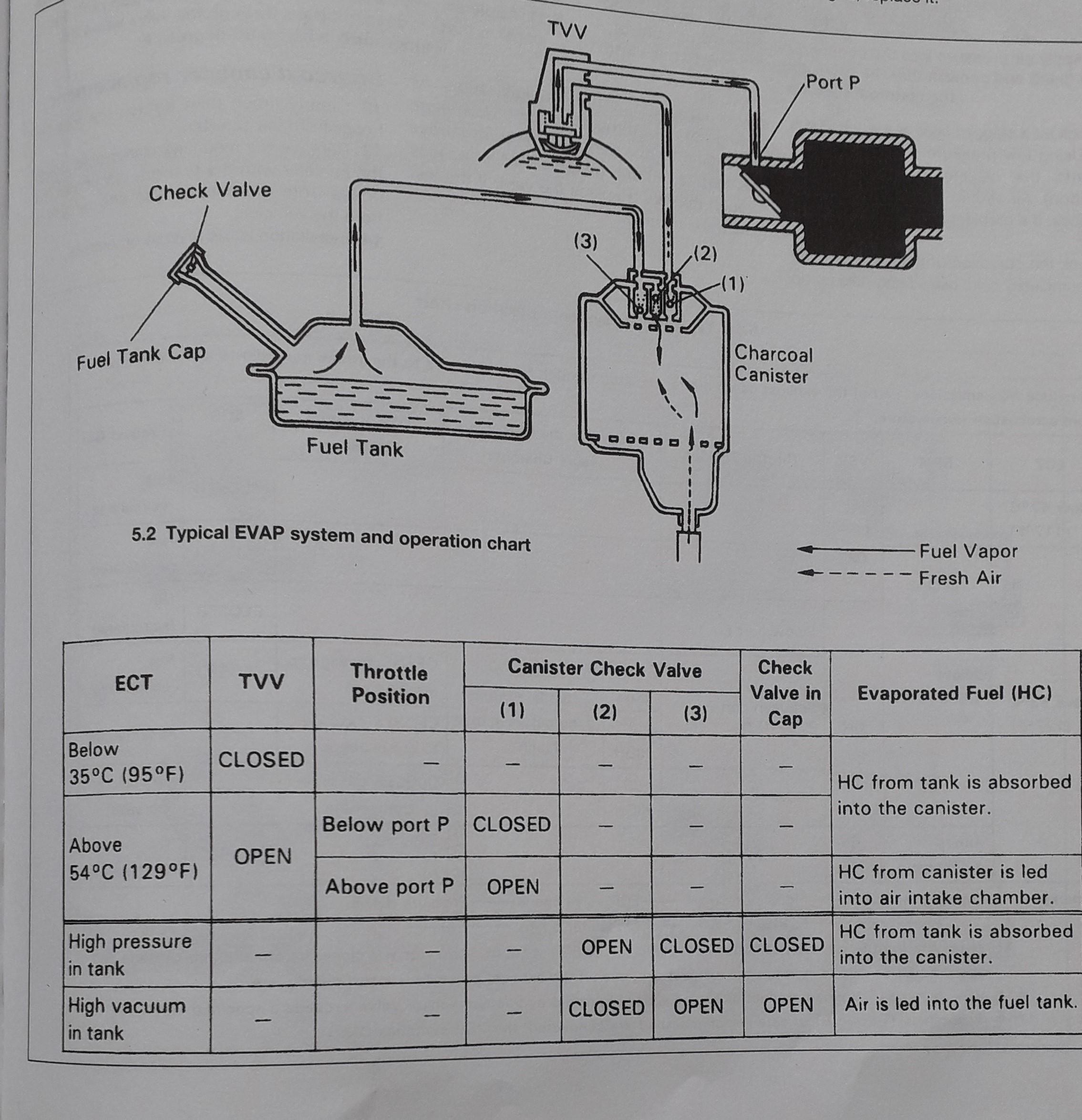
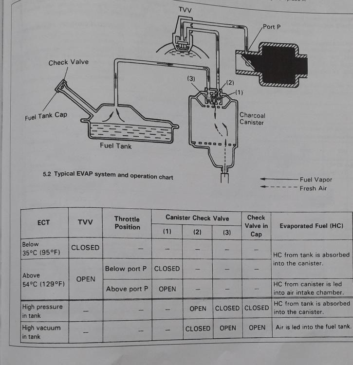
Fuel tanks should be able to breath in and out, or vacuum is created when fuel is used or temperature decreases and as temp. increases pressure builds up in the tank. Are you sure its vacuum and not pressure? I know the systems are slightly different but I have attached a diagram detailing the corolla 92-97 4efe setup. Might be of some help to get the brain thinking or following hoses around the engine bay. The TVV valve on the corolla (and starlet) is a coolant temperature dependant open / close valve situated on the thermostat housing. Is this replaced with a solenoid on the 4efte?
-
Excellent work, great write up too. 👍
-
Claymore's sleeper 4efe+t-t+t build (R.I.P. the Nanza)
Claymore replied to Claymore's topic in EP91 Progress Blogs
Thanks James, I have been impressed with your build thread also, great level of detail and well written. -
Claymore's sleeper 4efe+t-t+t build (R.I.P. the Nanza)
Claymore replied to Claymore's topic in EP91 Progress Blogs
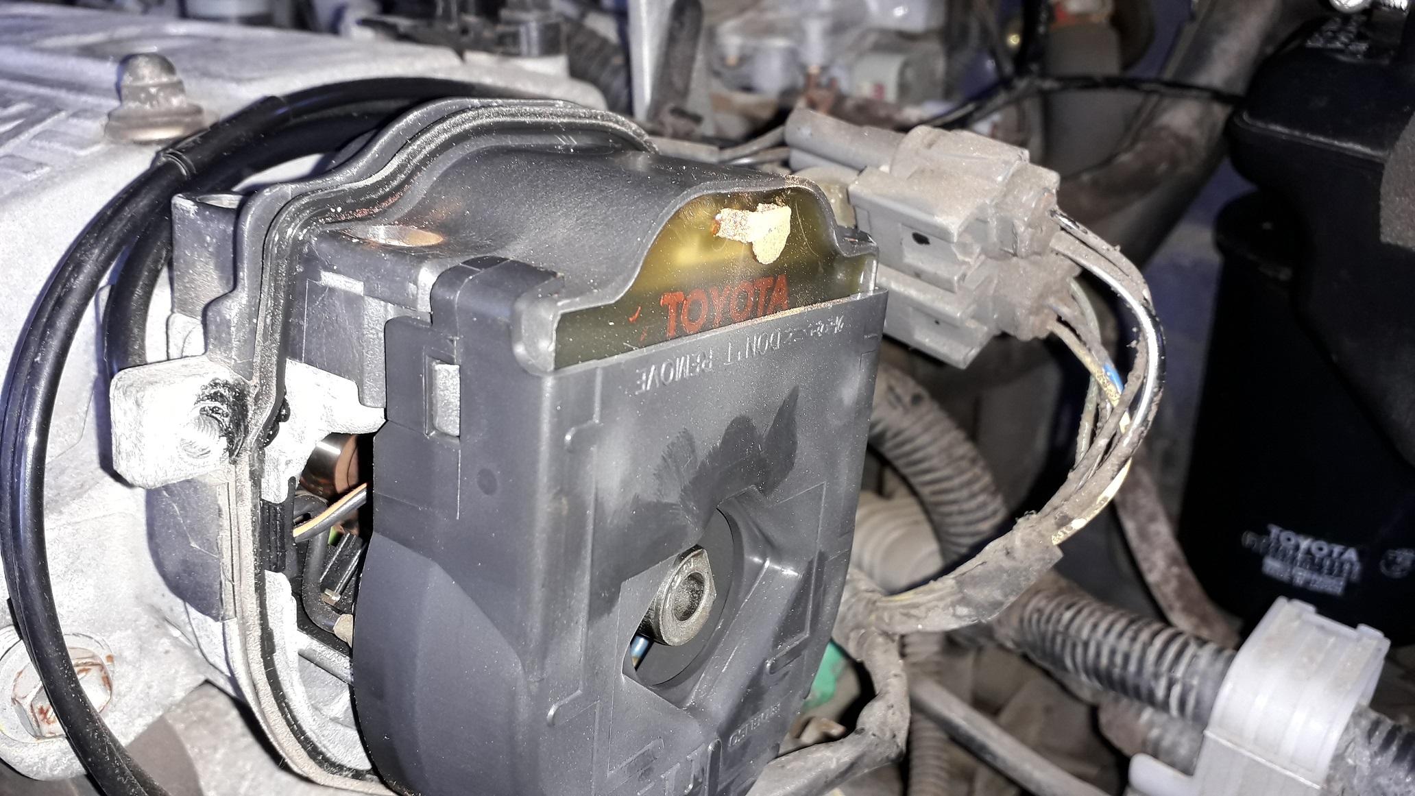
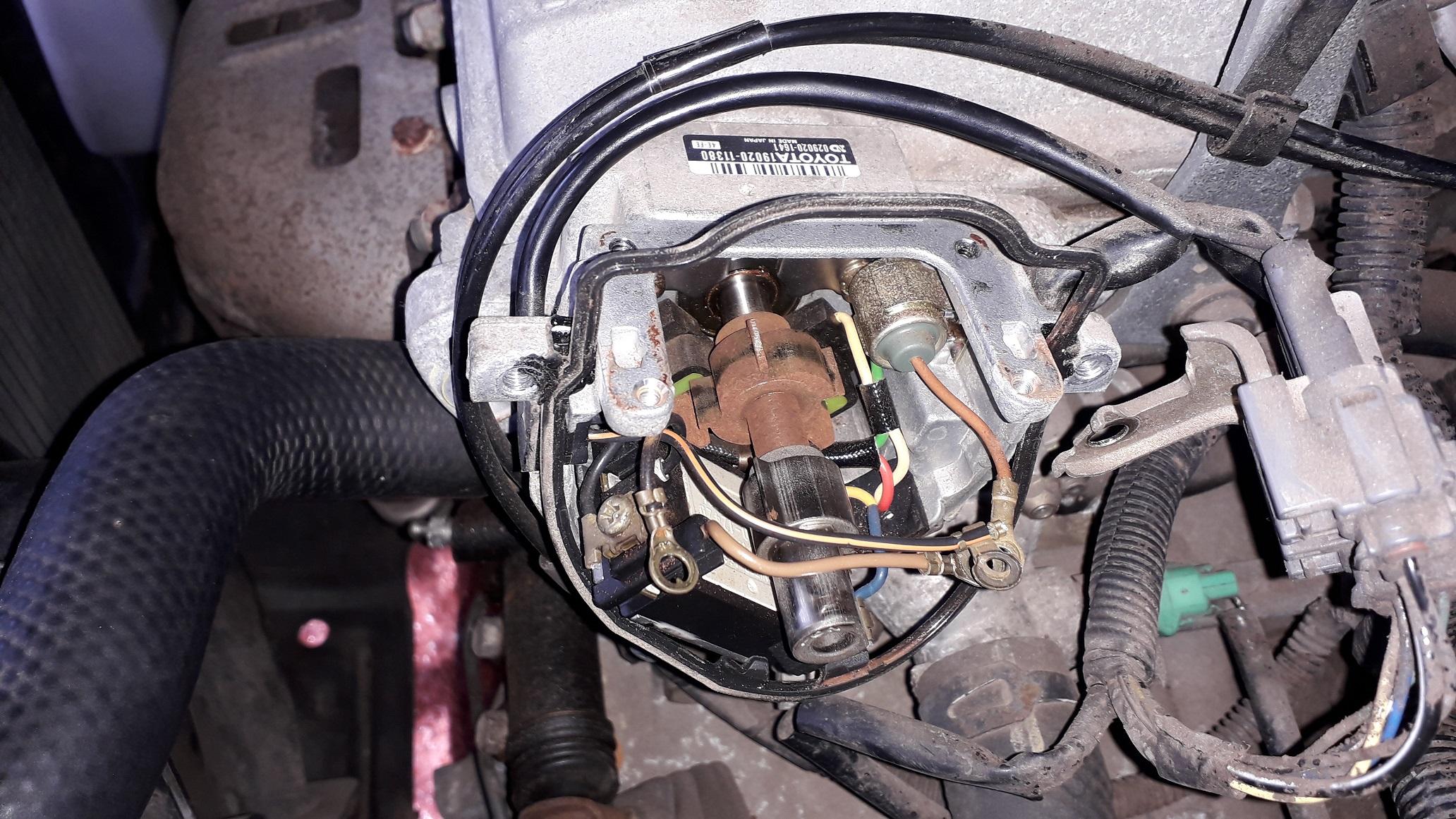
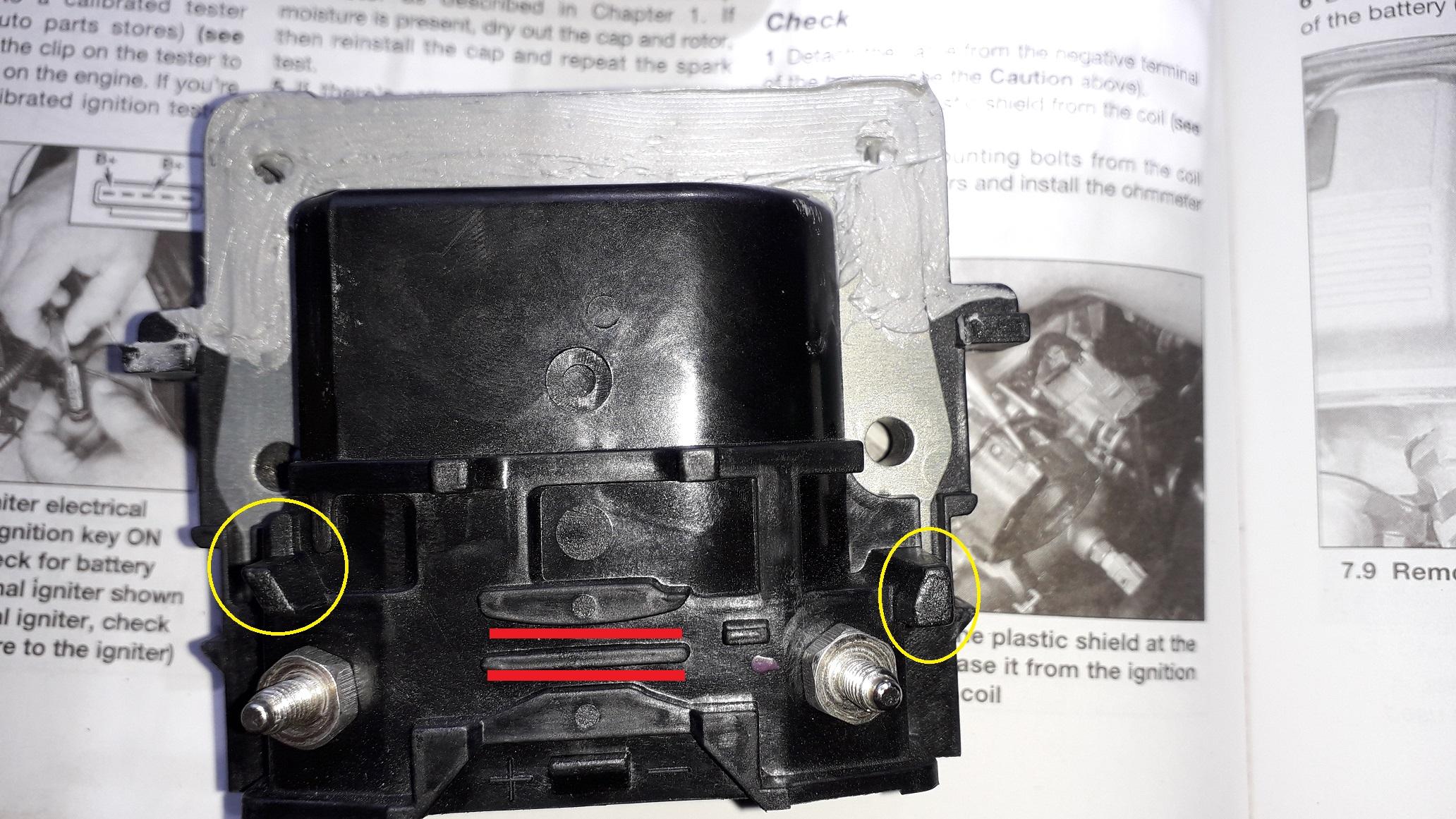
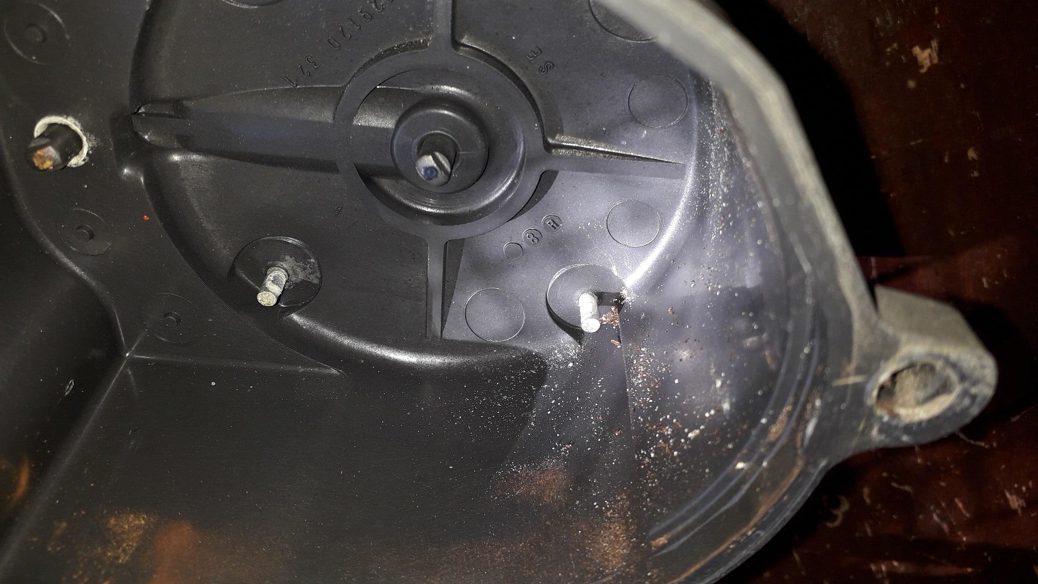
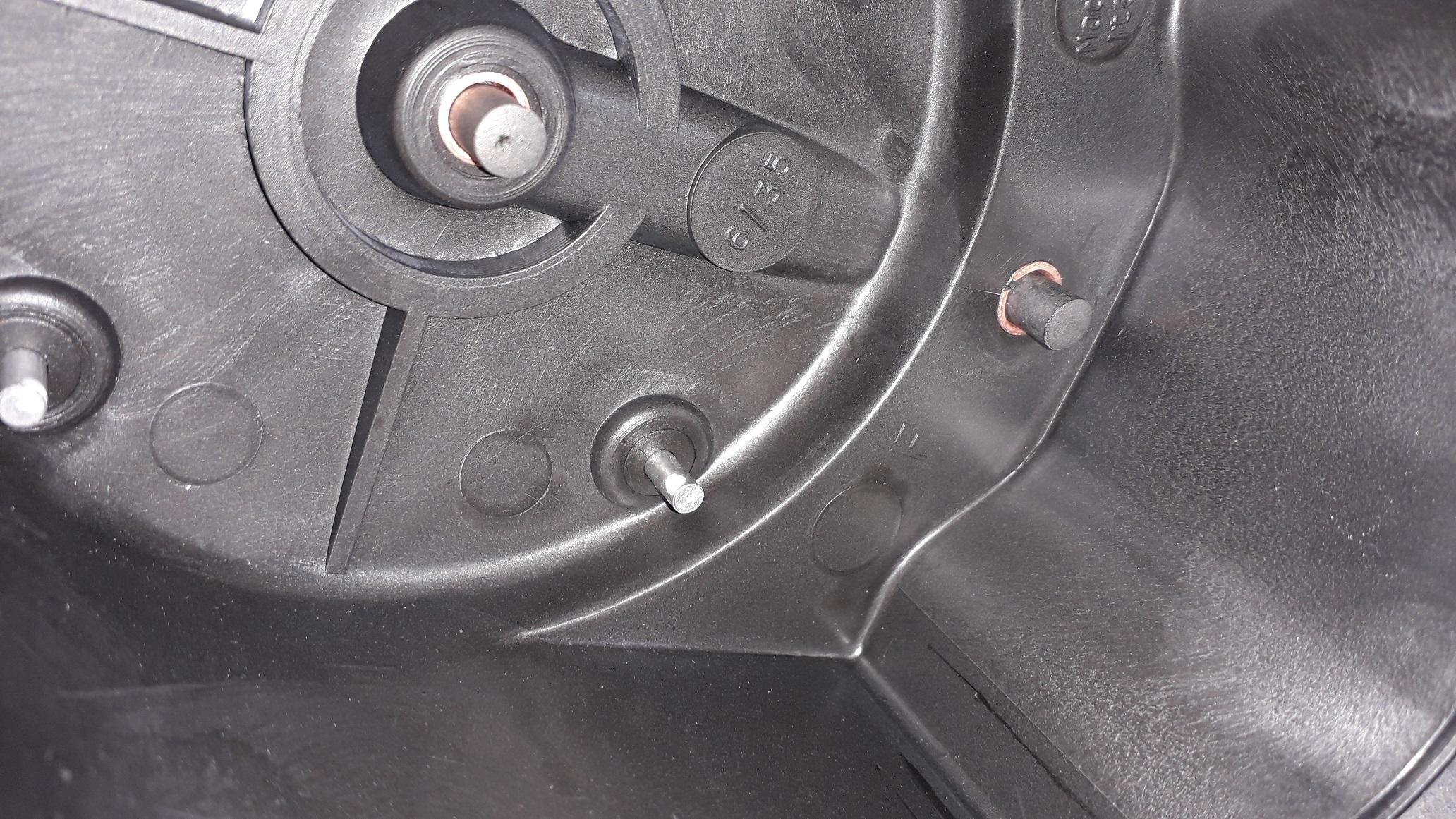
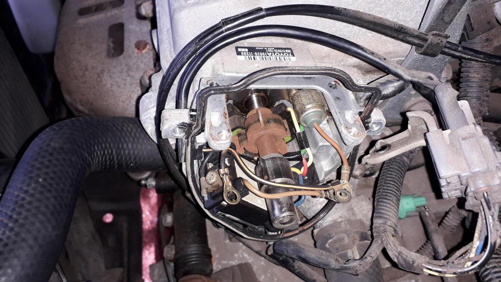
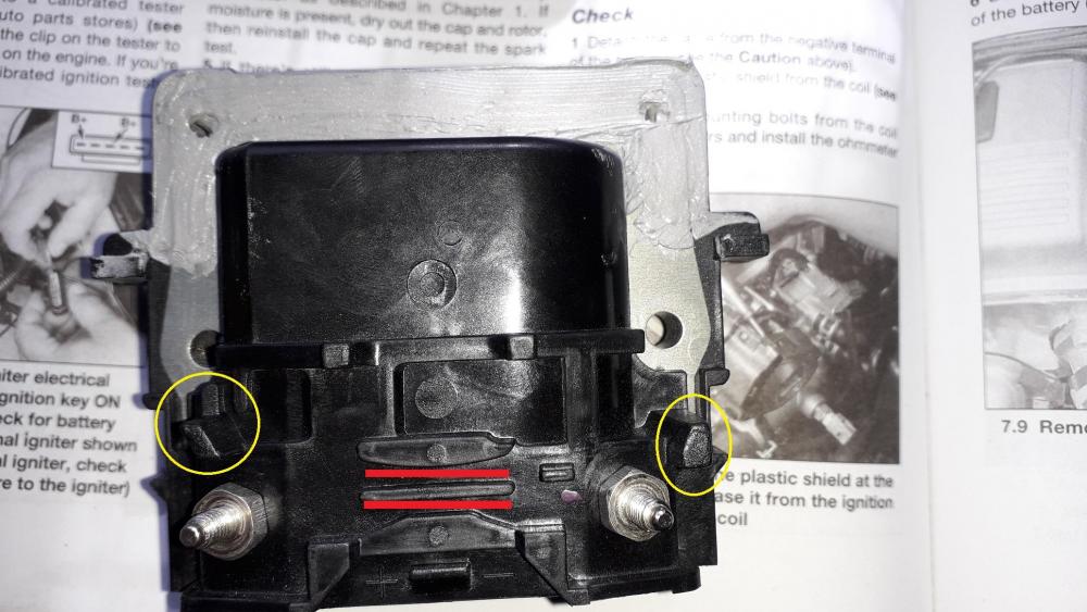
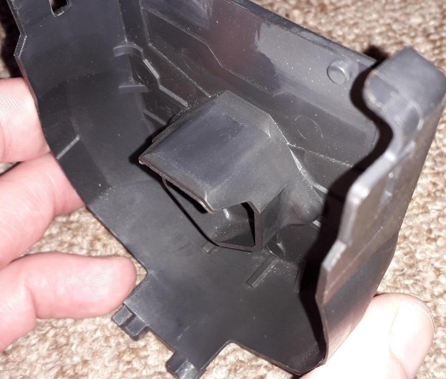
4efe Coil replacement: Whilst replacing the previous components I notice the coil contact was on the rusty side so decided to replace it. With the dizzy cap off the rusty terminal was obvious, not much clean metal to make contact with the cap contact. Then the dust / protective shield can be removed (yes, the one with don't remove moulded onto it!) by stretching the sides out, off the clips on the coil. Then you can access the 2 x terminals underneath to remove the nuts and release the connected wires. This only leaves the 4 x screws on the top of the coil to remove. The coil is sealed to the distributor body with sealant which I carefully overcame by tilting the coil up. There is a rubber gasket seal that was stuck with sealant to the distributor body which you have to be careful not to break trying to remove it or when lifting the coil. I left it in place and slid coil out. The important stuff found below, 4 bladed trigger wheel with dual pickup, igniter assembly, condenser. There is also a single bladed wheel in front of the 4 bladed wheel that doesn't have a pickup as far as I can see? Might be possible to use this for cam position for sequential management? Any how, replacement coil with sealant spread ready for assembly. I got quite excited seeing the amount of effort and engineering Toyota have put into the distributor assembly. The red highlights below show there are two tracks in the coil casing to keep the wires to the coil terminal tidy and safe away from the rotating trigger wheel below. The posts circled in yellow are there for the wire ring connectors to stop against as you tighten the terminal nuts preventing the wires being damaged from turning with the nut. Re assembled coil to dizzy, wires on terminals, pressed into coil tracks, then dust shield back on. Also noted on the back of the dust cover there is a flat hood section that extends under the coil to prevent any wires that come loose from dropping down onto the rotating assembly! Belt and braces Toyota, love it! If you made it this far, well done and thanks for sticking with it. 😜 Put the dizzy cap back on (which has a sliding fit over the dust shield and coil to prevent the dust shield detaching from the coil in use.) and changed the plug leads also for new items. More suspension mods next.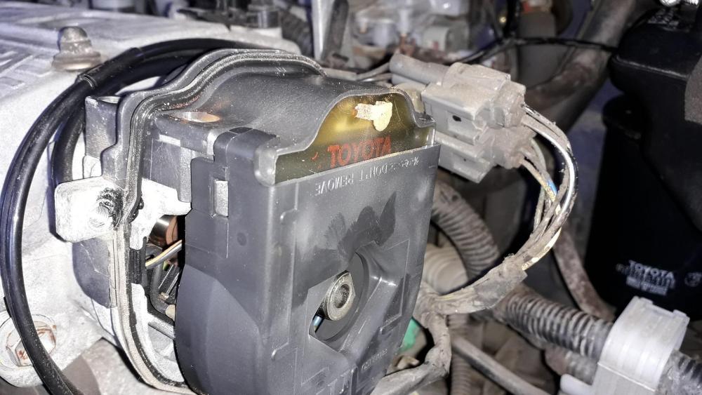
-
Claymore's sleeper 4efe+t-t+t build (R.I.P. the Nanza)
Claymore replied to Claymore's topic in EP91 Progress Blogs
Thanks mate. -
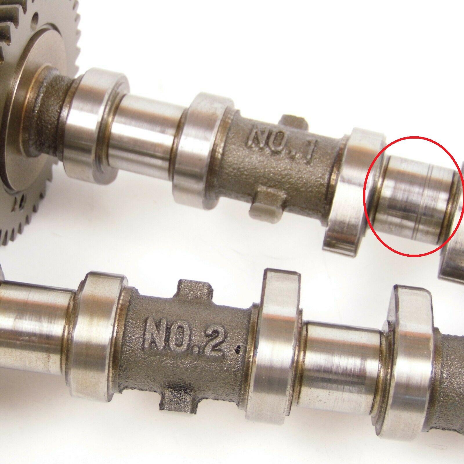
There is some pretty deep scoring on one of the no.1 cam journals though. Might clean up might not.

-
Speaking of overpriced rocking horse sh!t https://www.ebay.co.uk/itm/2X-Genuine-95-99-Toyota-Cynos-Paseo-L50-1-5L-5E-FHE-Engine-Camshaft-Cam/124247518298?hash=item1cedbaac5a%3Ag%3Ay84AAOSw1tVfANXb&LH_ItemCondition=4 Not checked the part numbers out No connection etc... Might be of interest to someone.
-
Claymore's sleeper 4efe+t-t+t build (R.I.P. the Nanza)
Claymore replied to Claymore's topic in EP91 Progress Blogs
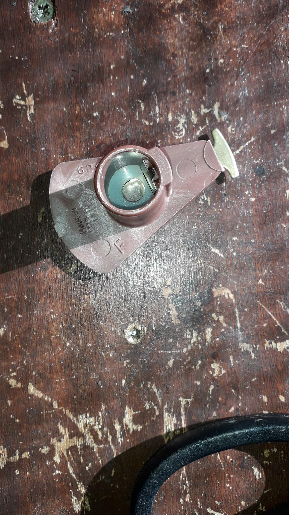
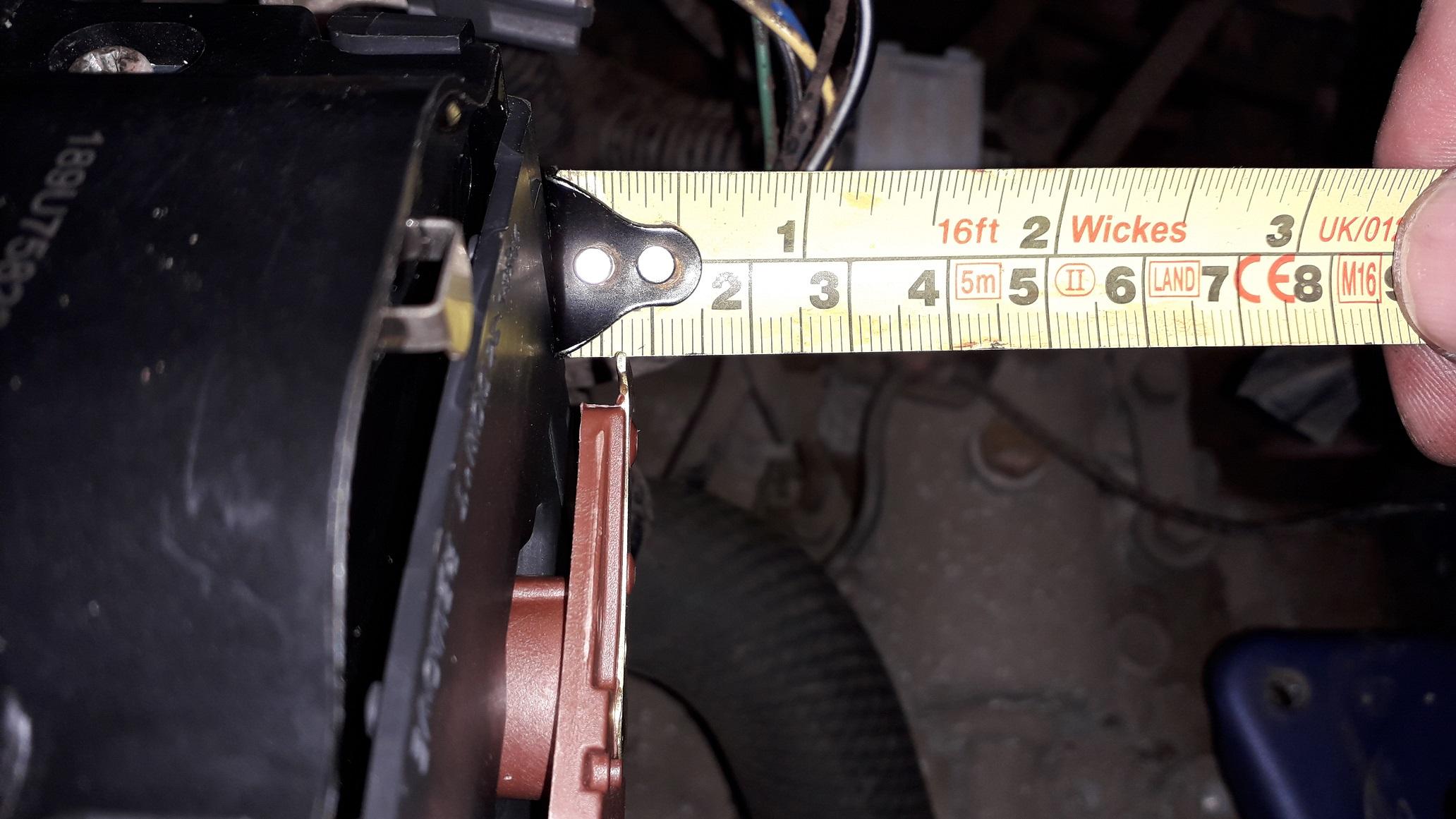
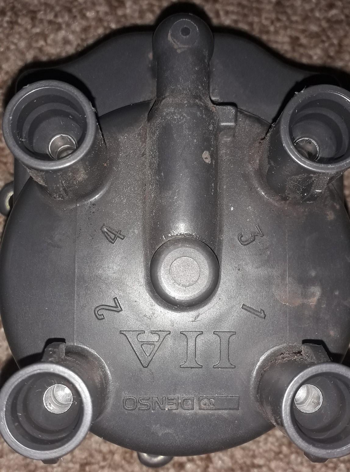
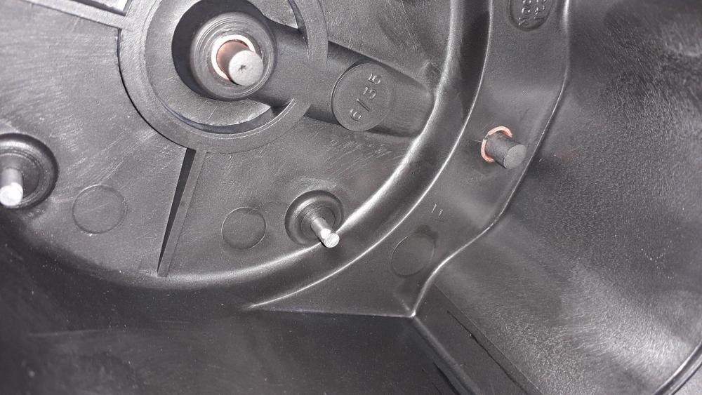
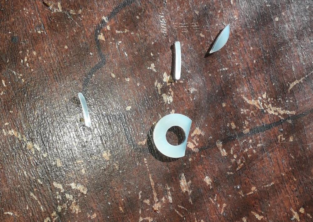
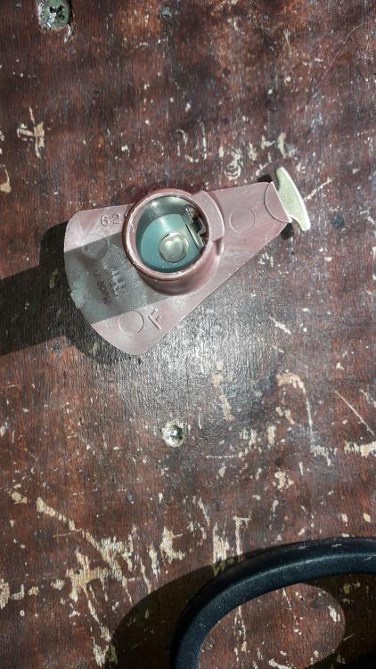
Distributor cap and rotor arm replacement: Carrying on the theme from last time I decided the dizzy cap and rotor arm needed replacing, bought an Intermotor cap and a Beru rotor arm. Removed old cap with leads still attached by unscrewing the 3 x fixing screws. Old cap was showing signs of spark erosion and corrosion on the terminals. Plenty of white crusty build up. Also some rust dust which I will come to later. Removed the old rotor arm by pulling out, away from engine (was very stiff to remove). Fitted the replacement rotor and noticed straight away that it sat closer to the distributor than the original Denso item. Swapped the old leads over to the new cap one at a time to prevent mix ups (thankfully the old cap has the plug wire positions moulded next to the posts.) re assembled and test started the engine. Sounded fine but I wanted to see how the new rotor arm was performing. Removed the cap and the spark erosion was at the tip of the terminal, Ok when new, but as the terminal is eroded it would have increased the gap making it harder for the spark to jump. Decided to make a non conductive polymer shim by cutting the side of a nylon washer with some poultry shears. This washer shim was the thickness required to move the rotor back out to the original rotors position. Seated snuggly in the arm so it wouldn't fall out. Re-installed, I checked the distance and it matches the original. Replaced cap, ran engine and inspected cap again! Erosion now in the middle of the cap terminals as it should be. This is supposed to be the easy stuff! Toyota O.E. parts next time I think. Old cap to show wire positions.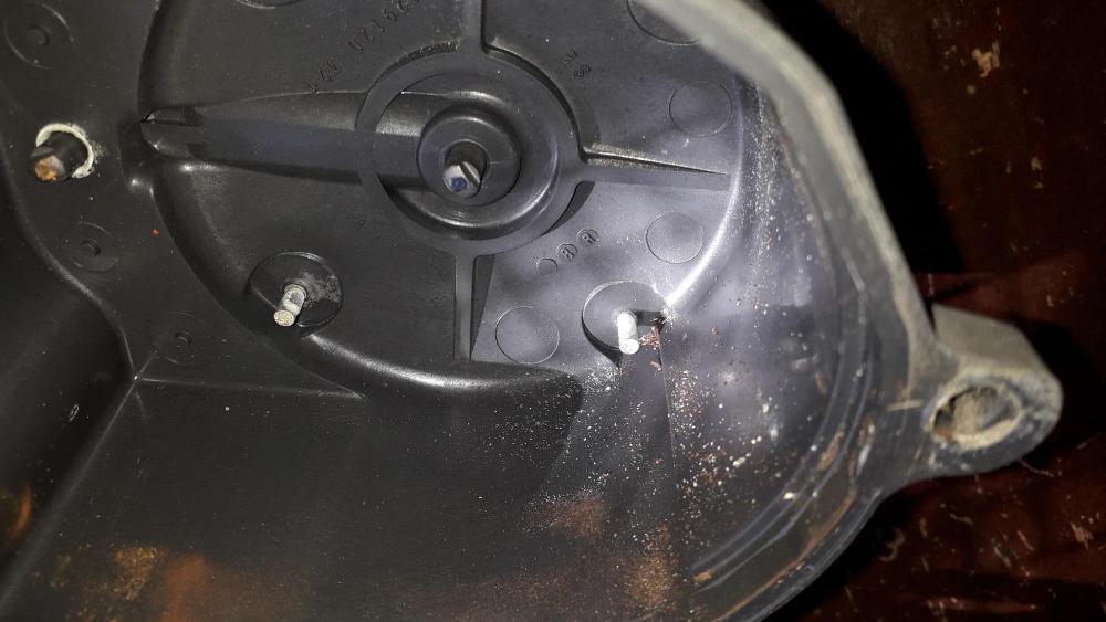


-
Welcome to the forum, don't forget to start a build thread. https://www.ukstarletowners.com/forum/70-ep91-progress-blogs/
-
Really impressed mate, great design and fabrication work. Even anodised your own parts. Top work
-
Claymore's sleeper 4efe+t-t+t build (R.I.P. the Nanza)
Claymore replied to Claymore's topic in EP91 Progress Blogs
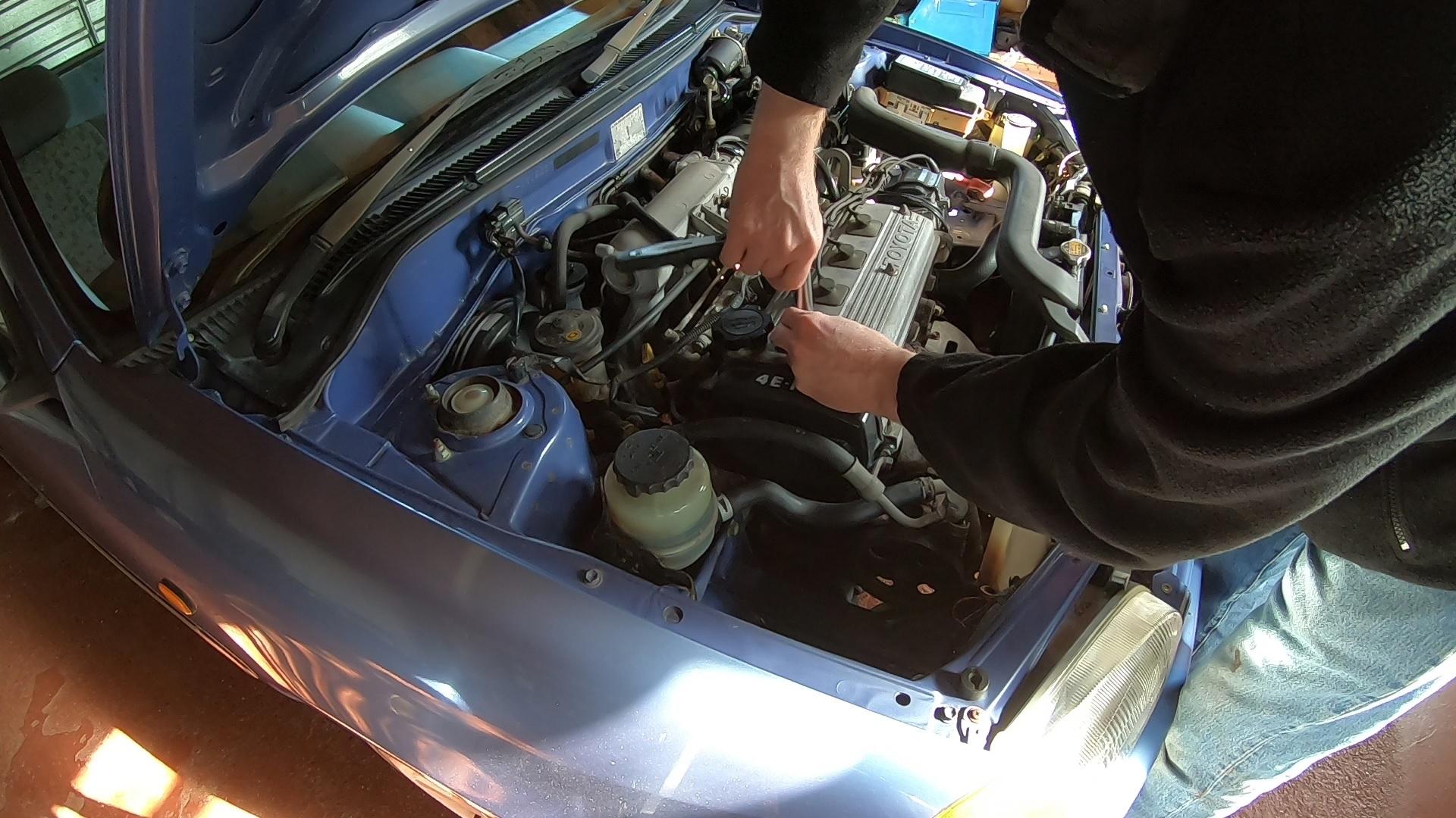
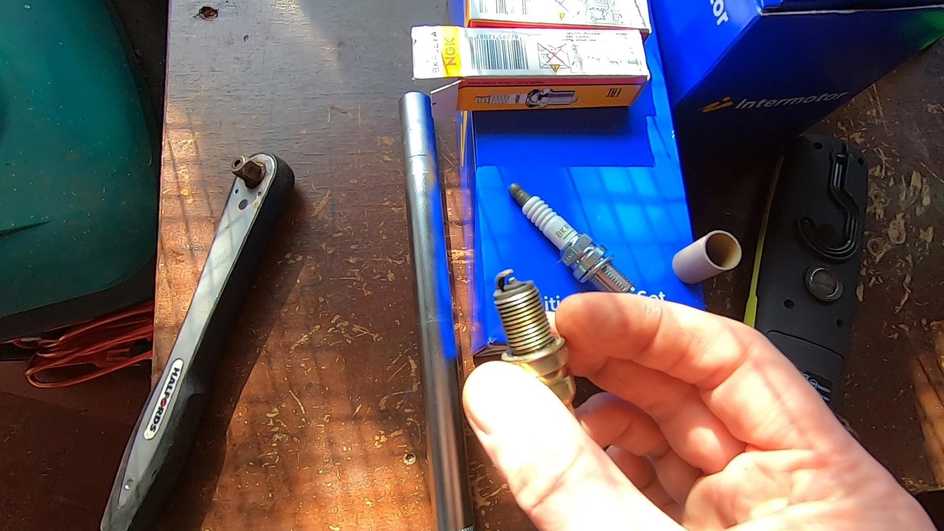
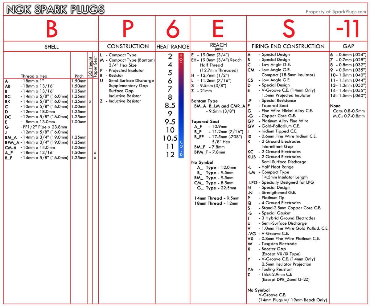
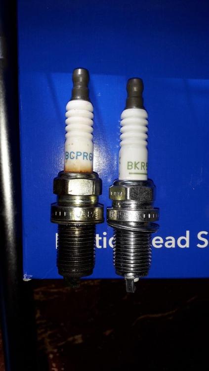
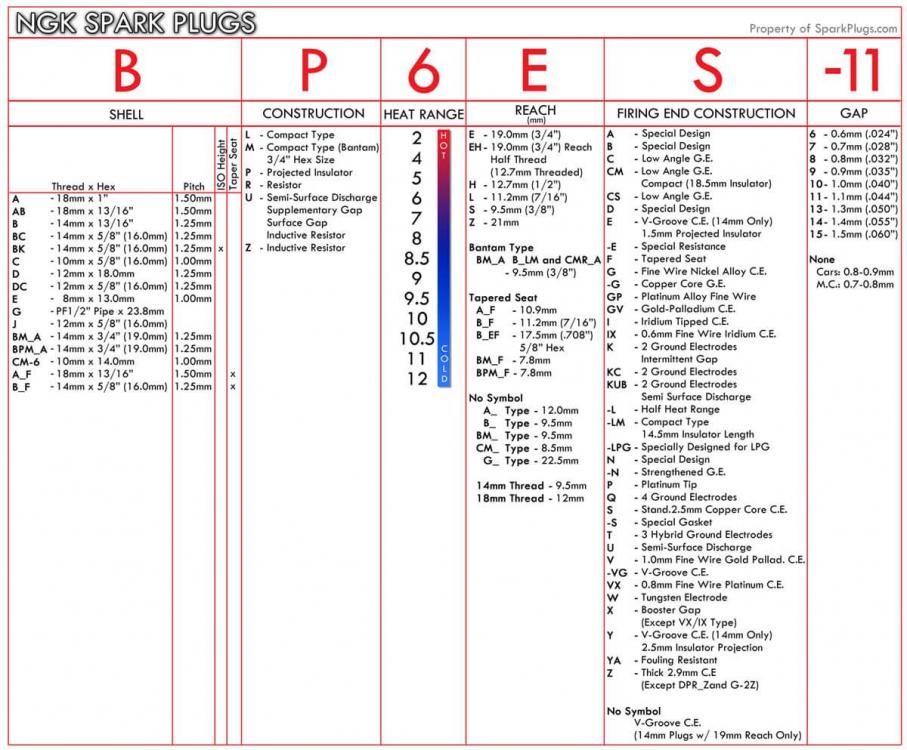
Spark plug change. https://www.youtube.com/watch?v=srafacg4tSU Bought some NGK BKR5EYA plugs as these are the standard plug specified for the N/A Starlet. Checked the hole for debris before removing the old spark plugs one at a time using a 16mm magnetic spark plug socket. They felt pretty sticky but thankfully came out without issue. WD40 can help but I was ok without. Greeted by the the wrong spark plug! It had BCPR6ES plugs in it for some unknown reason. Not only the wrong heat range but the height of the plug from the sealing washer upwards was longer by about 4mm. Hence the reason the HT leads never really pressed down to the cam cover properly. Thankfully the plug length into the head was the same or the tops of the pistons may have introduced themselves. 😱 The new plugs were the correct gap from factory so I installed them one at a time, I like to turn the socket anti-clockwise until I hear the "click" of the first thread engaging with the head to prevent cross threading. Then thread them in by hand and finally attach the torque wrench and tightened to 18Nm. I don't use anti seize compound on the threads as the spark plug manufacturers say not to, it also affects the torque applied. Quite easy and necessary by the looks of the old / wrong plugs. NGK code data from NGK website for those who are interested in that sort of thing.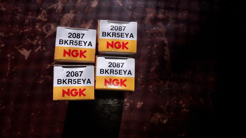


-
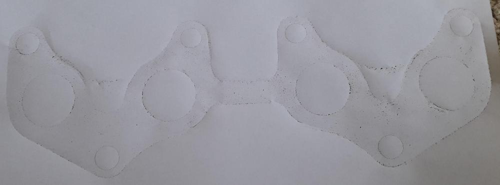
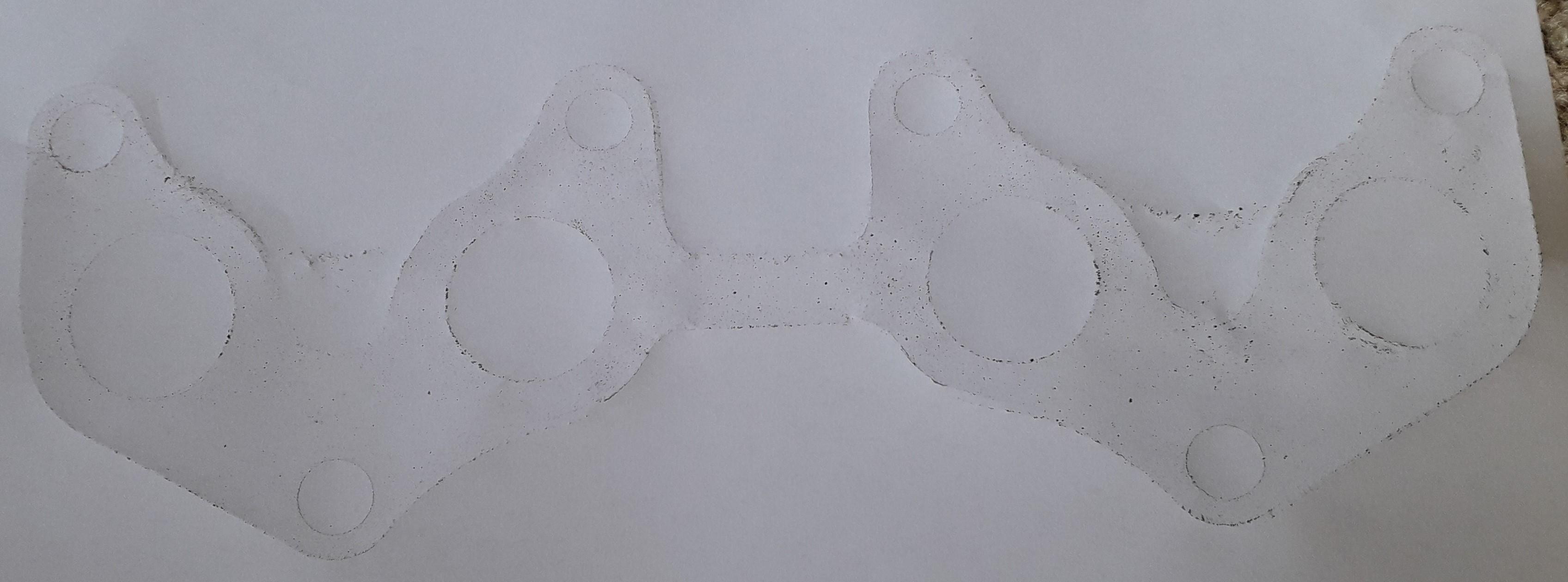
I've made a rubbing of a standard 4efte exhaust manifold flange which should help. PM me your postal address (If you can, sometimes new accounts don't have the privilege) I can't PM you. Or post up an email address and we'll sort it out that way.