

Stu
-
Posts
1097 -
Joined
-
Last visited
Content Type
Profiles
Forums
Wiki
Media Demo
Events
Everything posted by Stu
-
Is the AEM not reading any input signal when cranking? Looking at the dizzy plug (ie from wire side) with the plug latch at the top the 24tooth pick up is the far right, sync is second in from left, ecu sensor ground far left if you need it. Double check your using the right inputs. They're not hall effect sensors EDIT: What sort of filtering does the AEM have if any?
-
No worries!
-
Looks like the hard line from the turbo actuator up to the high/low boost solinoid - wont cause your issue How much boost are you running? 12 is usually a signal issue from the dizzy to ecu
-
Quite often its the idle control assembly under the throttle body - give it a good clean out or even bypass it to see if there is any change
-
Yeah thats a speed sensor error code - pretty weird to get thou. Sure its 42 thats coming up?
-
I'd start by continuity checking between your intercept wires and the dizzy plug, make sure they're going to the right pins. I don't have the aem software but can you check its registering rpm when cranking? It may need the cam sync - most aftermarket ecu's I setup do need it
-
Ah, its only a plug in. Just downloaded the software and manual, clunky... Yes use NE and NE- for crank pickup (reluctor/mag) Use G for cam sync (reluctor/mag)
-
Ignition problem, possibly relay. not too sure :(
Stu replied to TheDom's topic in Ignition & Fueling
Loose connection in the fuse box? -
They connect to various things - injectors and the ecu are the main ones. The earths to the ecu are called power earths which carry load current, the ecu then supplies sensors earth to the sensors which it monitors for interference against the power earths which is why its critical that important sensors like the map sensor and water temp sensor are connected to the sensor earth from the ecu and not direct to the head.
-
I assume you are wiring in an aftermarket ecu? There is a 24tooth wheel and a sync wheel (two syncs) inside the distributor below the rotor which tells the ecu the engine position. They are reluctor type triggers. NE is the 24tooth trigger usually TRIG#1, G2 is the sync usually TRIG#2 (Note, depends on which ecu you are wiring in), don't normally need the second sync. Looking at the distributor plug from wire side), Trig#1 is the far right, TRIG#2 is second one in from left, far left is ground to ecu SIGNAL EARTH not main earths. IGT is the output from the ecu to trigger the ignitor (spark event output). IGF is a feedback from the ignitor to the stock ecu to confirm there has been a spark event - if there isn't any feedback the ecu will show a fault code. This isn't usually required for aftermarket ecu's. STA tells the ecu the engine is cranking which enriches the main injectors for cold start essentially.
-
NE and G- are 24tooth and sync respectively
-
One of the issues with the 3s fitment is how low you have to mount the engine which in turn upsets shaft angle and how much you can feasibly lower the car. Yep best to stick with an e series box. Believe one of the camry boxes is physically the smallest and helps fitment
-
Did you get any water in the diagnostic plug? Can cause issues.
-
(4EFE -T) Emanage Ignition harness - Intermittent starting
Stu replied to jimlols's topic in Electronics
Interesting but my thought is that the stock ecu is still supplying the ignition spark event and it calculates engine position via the 24tooth and sync trigger inputs from the dizzy. The emanage only adjusts the duration of this +/- for each pulse. Think about a stand alone ecu, not IGF signal is needed. Thoughts? EDIT: By the way, the IGF wire may not be shown on the pin out diagram but always check the actual pin IDs by taking the cover off the ecu - they're printed on the board. -
Definitely clutch type - you can shim them so they drive/lockup as you want them to suit your intended use ie street/track/strip
-
Poor earths is usually the fault for the clock - as above, rip it out, clean it all up and re tension the pins in the plugs so the grip tightly.
-
(4EFE -T) Emanage Ignition harness - Intermittent starting
Stu replied to jimlols's topic in Electronics
Take a close look at all of the pins and connectors to the emanage - sometimes they can become loose especially as these are often second hand units that have been through a few vehicles. I've had this with a few ecu's I've setup and found the connection works for starters but after a drive/vibration they can cause issues. Have you tried turning off the ignition map and seeing if this makes any difference (ie ignition from the stock ecu runs un-adjusted) - you could also try to zero the ignition table and see if that makes any difference. This would rule out a software or config issue. With the ignition harness I take it your only using one channel in and out? Its been a while since I've worked with an emanage but you could possibly try swapping to another ignition channel? I've just opened the software but need an ecu connected to get to the full config - you might be able to stipulate which ignition channel your using. The stock ignitor which I assume you are using is termed a 'dumb ignitor' with dwell controlled by the ecu - so you can run this without an IGF signal. IGF just tells the ecu that there has been a spark event - on a 4efte ecu if no IGF signal is recieved after a certain number of IGT events it will throw a fault code thinking the ignitor is faulty. It doesn't serve any other purpose. I would assume the 4efe ecu being a more basic setup would just not utilize this feature. Not sure if you have an oscilliscope or not - you could check that the output waves from first the stock ecu so you can see the waveform pattern then from the emanage (with zero tables) to make sure the wave forms are the same shape/frequency. You could rig a drill onto the dizzy to test this without having to crank the engine over for long periods. Lastly, the rotary switch settings - essentially the 4efte ingition system uses the same VAST system as the 4age does - and the 4age rotary settings are 2,4,2 but as you say, you've had this running so I doubt any of the jumpers or rotary switch settings are at fault. -
http://www.mearcat.com.au/docs/EP82%20Starlet%20Wiring%20and%20Connectors.pdf
-
Sorry, TK test. Its the technical name for the "sniffer" test. Shows if their is any combustion gasses in the coolant. Could also pressure test the coolant system and see if its leaking back into the cylinders. You do get moisture out of the exhaust on start up/warm up - its condensation from cold exhaust/hot gases, but this should go after a good drive as the whole exhaust system should get pretty warm.
-
Thanks dude. Yeah I have and my ecu will run 8 injectors sequentially so I can still run antilag and sequential idle etc but there isnt much point in running 8 as I can just buy bigger injectors if I need them. Im running a 044 pump so there shouldnt be any reason I wiuld run out of fuel. I wont be running it on e85 so 760s ahould be heaps. Staged sequential setupa just seem overly complicated for not much advantage to me.
-
The bolt on supercharger kit wakes them up - really nice drivers car
-
Its been so long since ive worked on a 1e/2e but are the rockers adjustable? Are the valves actually fully closing? If its not shimmed right it might not have enough seat pressure and air is squeezing past the valves? Doesn't explain white smoke thou, that sounds more like a head gasket to me. PK test will tell you.
-
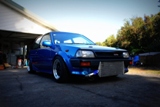
Looks good with the blue filter! Left hand drive too!
-
Oh, forgot to add, I had the injectors for Garreths car tested the other week prior to tuning so this week I took mine down for the same treatment. Im using some 760cc Siemens units which should do the trick. Here's a photo of Garreths getting flow tested - didn't get a photo of mine being done as I just dropped them off this time. Money well spent making sure they're spot on.
-
So have shifted back to working on the engine again. I hadn't quite finished off the inlet manifold so I spent a few hours with the dremel cleaning up the welds around the injector ports inside the runners. Shaped them all with the carbide bit so they looked like the above then swapped the bit to a sanding drum and tidied them up. Also welded a plate onto the underside and drill and tapped the NPT hose fittings for the brake booster and vac line take offs. Then finalised the mounting of the idle speed controller. This is a two wire PWM bosch unit and will be controlled via the link to handle cold start idle up and load rpm adjustments (for headlight/alternator load etc) along with being the air bypass for antilag. I ran a similar setup on the old engine via the old Linkplus but with the G4+ the control is quite alot nicer. I wont have any of the issues of un-even idle or difficult starting that I'd seen with quite a few customers cars that have come thru. Should be able to adjust idle quite accurately and also have progressive warm up idle speed adjustment like factory. Here's a photo of the old setup - will retain the same bypass piping to the intercooler pipe. I was never very happy with using a stock 4age fuel rail as it had an extra mount that I wasn't going to use and the top mount reg and feed which I was going to have to fill and machine back. So, I bought some Aeroflow fuel rail extrusion and started to make my own fuel rail. I was thinking about centre feeding this with returns from both ends hooking down to the fuel pressure reg that I would mount under the inlet somewhere but in the end I decided this was overkill and end feeding was fine. Stock rail Aeroflow extrusion Chopped then rail to length, then used the milling machine to drill holes for the M5 mounting bolts. Then used a 10mm milling bit to recess the cap screws into the rail so the heads sit flush - trying to make it look tidy. Reamed the ends to allow the aeroflow -6 weld on fitting to slide inside the rail Then welded them on So it looks like this Copied across and drilled the injector ports Sat it all in place and measured up the spacers needed to bolt the rail to the inlet (already had tabs between the runners from fitting the stock rail). You can see the throttle cable bracket welded under the plenum, you can hardly see the cable so its quite tidy. Still need to trim the length of the idle speed controllers bypass hose. You can see the idle speed controller under the inlet Chopped the fuel rail spacers then drilled/tapped each end and fitted them. The rail is rock solid - fingers crossed there are no leaks. I've started buying the fuel rail fittings but need to mount the fuel pressure reg before finalizing the final fittings and pipe I need. Will be using stock piping from the 044 pump to the fuel filter on the fire wall, then -6 fittings and line from there to the rail > reg > return. If I looks like the stock fuel line will be a restriction then I'll change it but I'm hoping to get away with it. So this is where its at now. Next is mount the fuel reg, fit the fuel pressure sensor for the Link, and make up the lines - then the fueling side is all done. I've started to design the mount for the HEC715 coils, just need to decided on the final spot (somewhere over the gearbox probably) and the Link ignitor mounting location. Will mount the coils like this probably.