Sam44
-
Posts
1487 -
Joined
-
Last visited
Content Type
Profiles
Forums
Wiki
Media Demo
Events
Everything posted by Sam44
-
Definitely my starlet friend we share a common interest which I'm very much enjoying. All the systems employed are either common to modern day engines or past technology seemingly forgotten mainly because of high and higher hp targets or modern day turbo tech no longer requiring it. With such a basic older turbo and road hp requirements target mph times this system become eligible for us to use/test.
-
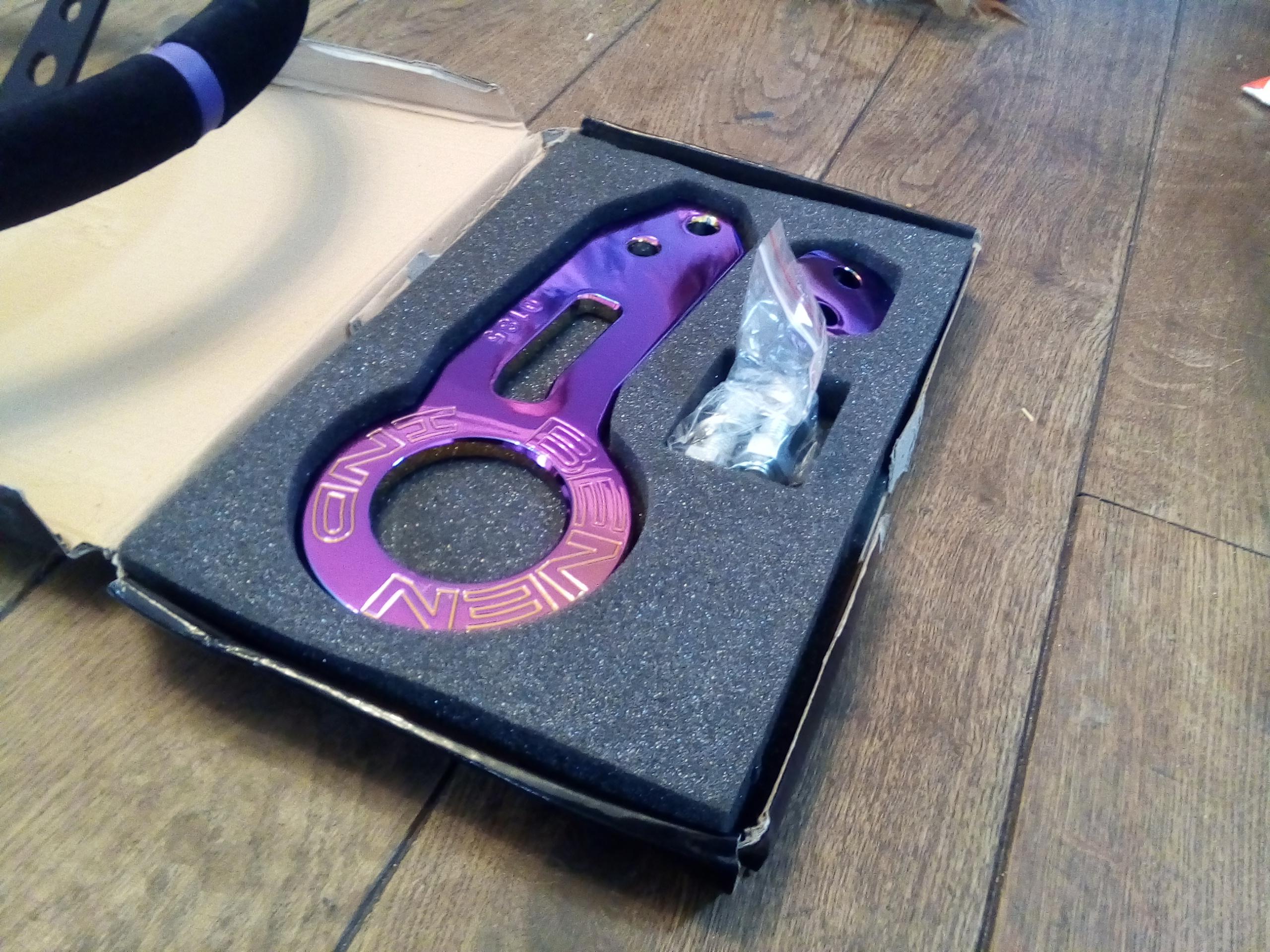
I've received these today. It's going to be a pain to Keep the track toeing hook looking like this. Only to be fitted for track with the reduced drag bumpers.

-
Put it this way what ever positive pressure (boost pressure) the seals can withstand on both compressor and exhaust turbine (exhaust back pressures, these are generally higher) the seals can equally take the opposite (negative) pressures. There is of course oil pressures to consider. I can see how you came to the answer you did. I've not explained the engine breather system. This is setup to maintain a set relatively constant negative pressure to stop piston double pumping (know as engine parasitic losses) and promote piston ring seal. Lol ive left this off here for now as I can imagine the head scratching going on. again this uses 3x 1way check valves, oil catch tank and an inline restrictor. Between these 2 the turbo will be able to produce say 3psi at a higher rpm than it would normally produce. as the actuator reacts to this set pressure the arm opens and volecity and turbo rpm take over. It can be hard to understand pressures and flow rates (volumes). And in most cases if you increase 1 it will decrease the other because restrictions will increased or decreased. these restrictions can also affect velocity/speed yet another area (venture affect). These restriction apply to both the intake and exit of the system/sytems. Look into turbo Serge and why this happens will help you understand alittle better. This also helps explain the blow off valve idea as a negative pressure is produced and the pressure increases with engine rpm raise/engine throttle opening in an enclosed intercooler system. A negative pressure/vacuume of around 20 to 23psi is our target. I do never mean Any of my questions to be offensive in any way. understand I'm on a club based web site. your questions are valid, I've not explained the full system or given any target figures. I ask my questions so I can best explain to you, gauging your understanding of pressures and volumes.
-
It's not fully closed. the throttle control arm will be setup to control negative pressure. How much negative pressure are you thinking about. You do realise the range of both positive and negative pressures, Do you understand engine throttle and manifold pressure. The engine breather will also be in the line between the turbo and pre turbo throttle. Answer to your edit: To answer your edit: that's if I'm on a straight strip run or quarter mile. Track and street or different altogether with a variation of widths and corner angles (exactly why this system was invented because the first F1 turbo engines struggled with out of corner acceleration against the already proven normally asperated counter parts) and that's f1/track use. Gordini famously wrote in his auto biography all other turboed engine drives complaine about turbo lag out of slow corners, his driver's asked what is turbo lag. Fantastic book a must read. When we get to the street stop and starting. the close ratio box using the 4+:1 ratio final drive lsd will combine to give killer 0 to 60 mph times. The turbo tech will allow me to jump gears and even move up earlier to get to the all important 3 threw to 4 (1:1 engine output gears). Now I bring this up Im missing the heavier 4e flywheel which stores more energy in the rotating mass which helps me to be able to do this keeping engine rpm up and power ready against the ultra lightweight and low anertia fast accelerating lightweight flywheel and small weight sensitive clutch I'm on at present. It's been areal bug bear. The only consolation is the flywheel was a second hand bargain and combined with the box and other mods it's saved me a small fortune and time on a digital ignition system. It's a poetic notion of driving at speed you have there, but in real action things get very interesting real fast. So yep the antilag system will increase the out of spool up turbo characteristics. The box is not really suited for strip use it tops out at around 140mph but I'm working on this trying to up the 4e engine torque levels to match the 5e which is great at hunting down them times. The 4e does better at advancing engine rpm (hp) what is know as a hp giver just lacks torque. On the strip using a 4e I'd run no lowwer than a td06 or equivalent with noss and more than likely methanol, the noss would be the antilag oh as well as the dog box from tunning developments using the high mph hitting 3+:1 final drive. That's the only way I can even see a 10second happening with out going all out visco spec.
-
Now we are talking what model and year are these from, I know Brad on here is running Celica dual acting caliper possible 4 pots, I'm not to sure. I'll look on his MK1 build. Brad is quite but really very clued up. I think he's even running a gto bigger master cylinder.
-
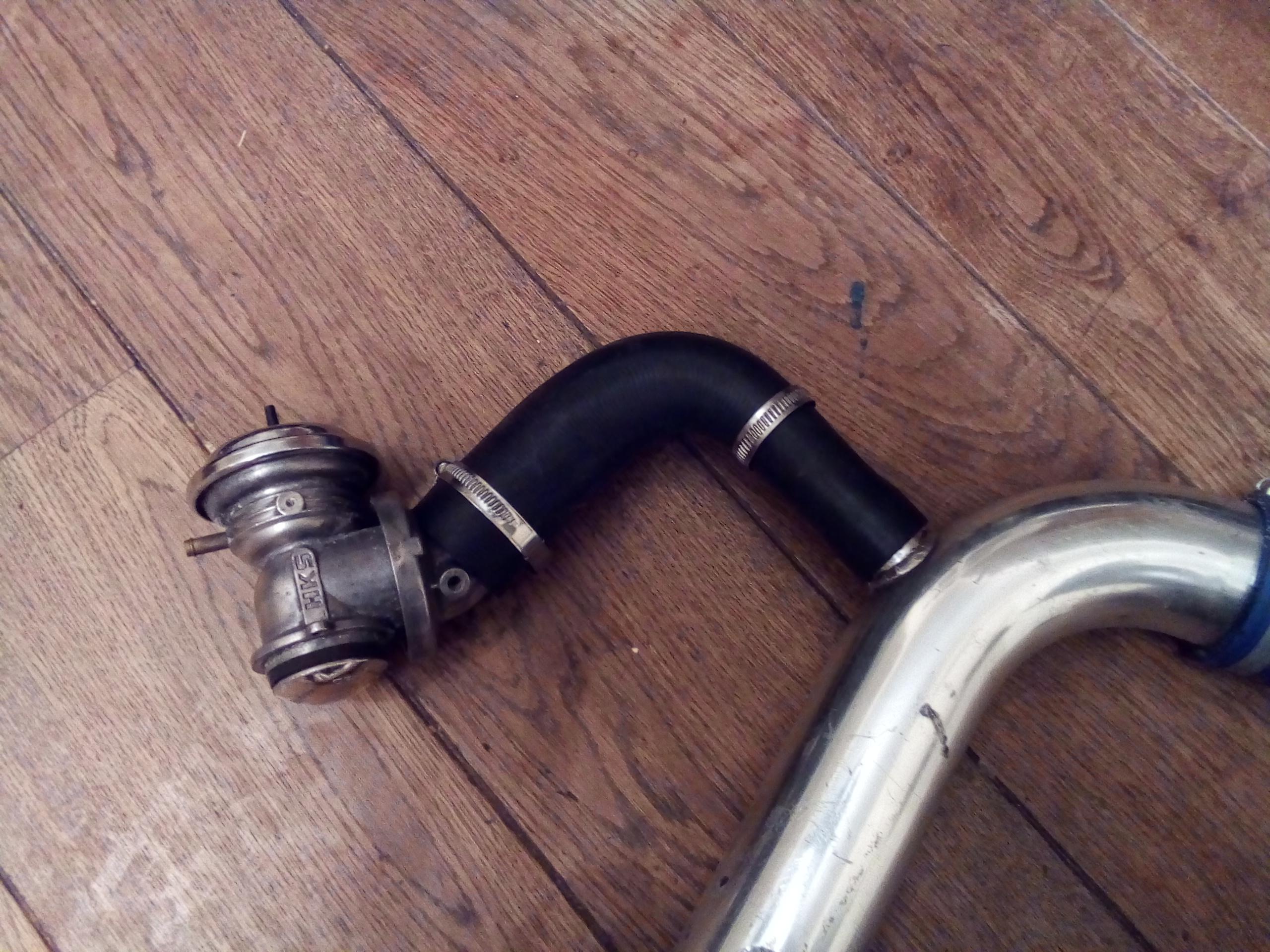
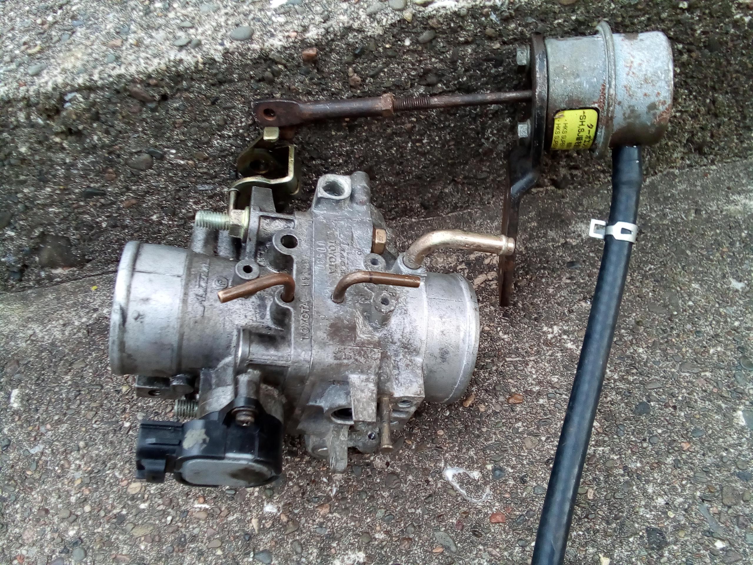
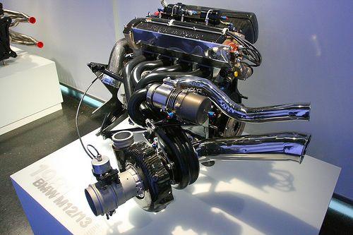
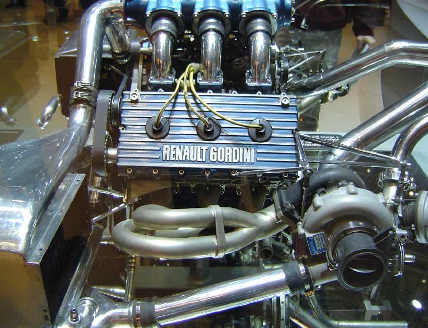
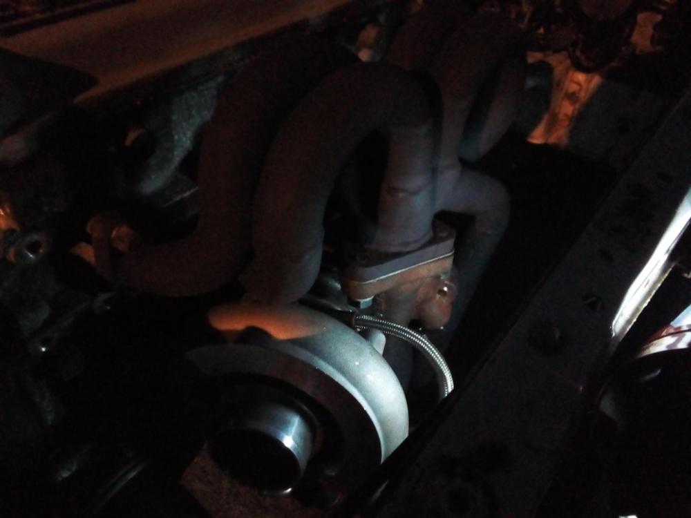
Your quite correct on the throttle body before the turbo. Gordini first introduced these on the Renault engine in the late 1980s F1 era to reduce turbo lag. It simple removes load/air from the compressor wheel allowing it to free spin. As the throttle opens slowly it increases air velocity into the compressor inlet. Massively mighty and equally impressive BMW 1.5 four cylinder 1980s F1 era 1500hp turbo engine sporting the before throttle body as seen. Also the V6 1.5 1500hp Renault gordini engine 1980s F1 also Other engines: honda & Porsche tag turbos also ran throttle bodies. Yep it's still the original 4efe engine, we have carried out full comprehensive test on the health of the engine, hydrolic test to check ring seal compression tests, oil pressure tests, leak back test to check valve seal. All came back spot on. The engine has been looked after, it was rebuilt with extras 2years ago. The oil will be tested for grade and contamination levels after the full setup is complete, mainly to check water, fuel, grade levels after 1 complete winter and summer cycle. I'll have to get in touch with visco about copies for sale but I do have the old original full kit that is good just seen better day I might sell. The 5e is to be forged with the early 4efte GT MK1 head the ports are located slightly better. It's curently going into another ep82 MK1 shell very slow build this 1 but with all the best bits. The additional pwm table on the aem ECU will operate the hks blow off valve located just before the engines throttle body it will run operate off the 4efe tps (potentiometer) on the pre turbo throttle body which opens off the hks adjustable actuator. The blow off will open at set low turbo pressures in relation to rpm/engine load. This will remove load on the turbo compressor wheel (both removing back pressure and incoming air to pump, creating a vacuum) and allow more air to enter the engine and drive the exhaust turbine. The hks actuator is plumed directly into the turbo compressor housing pipe (direct boost build). The car came with the Baily's bov valve (bucket type) I was warned about high maintenance if you do not run a oil catch can and good engine air filter, after some research I found the early hks blow off valve was the 1 for me very robust. The system might sound complex but it's really quite simple, the only real hard part is setting up the pwm table. The aim is to get the turbo spinning and keep it spinned. (Anti lag) 1 area we have got a trained eye on will be the engine throttle control, with all the modification we have brought to the simple 4efe system we are hoping to see a very smooth controllable throttle/power delivery helping the map sensor plot an actuate procise fuel delivery. (Engine efficiency).

.jpeg.1746eb1a0aa6142d3ea7b8530cd2c1c3.jpeg)
-
So so nice.
-
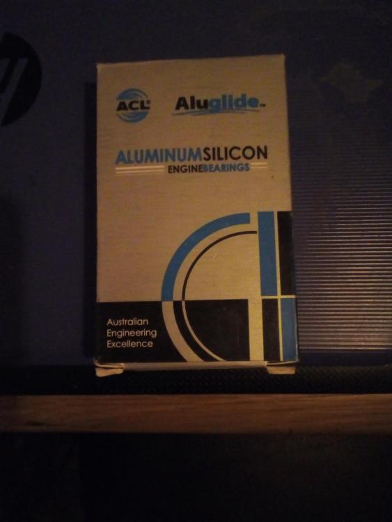
These came yesterday, new big end shells. after it's been dynoed and I've got the engine oil results back from being tested. These and the oil cooler will be fitted.
-
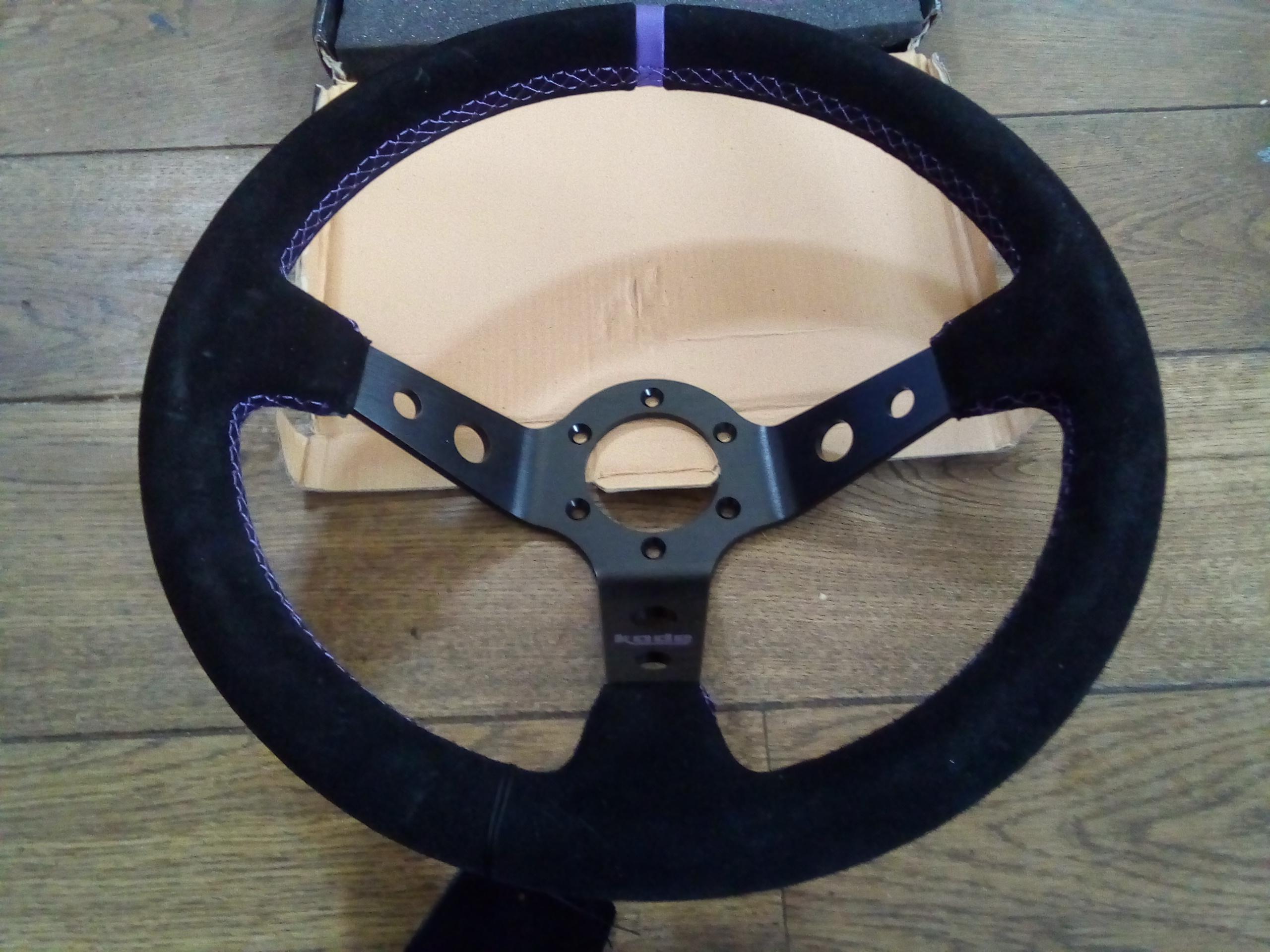
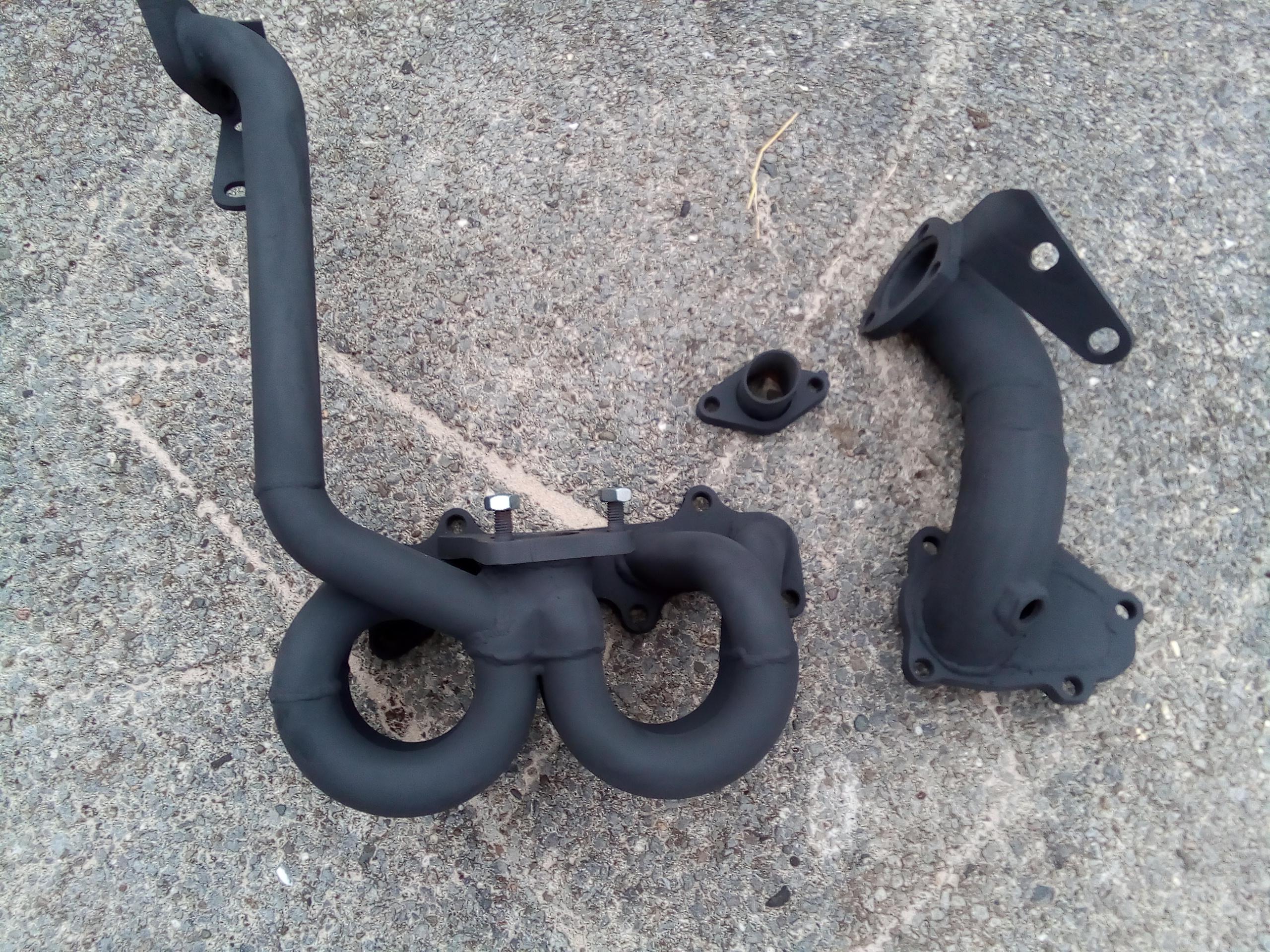
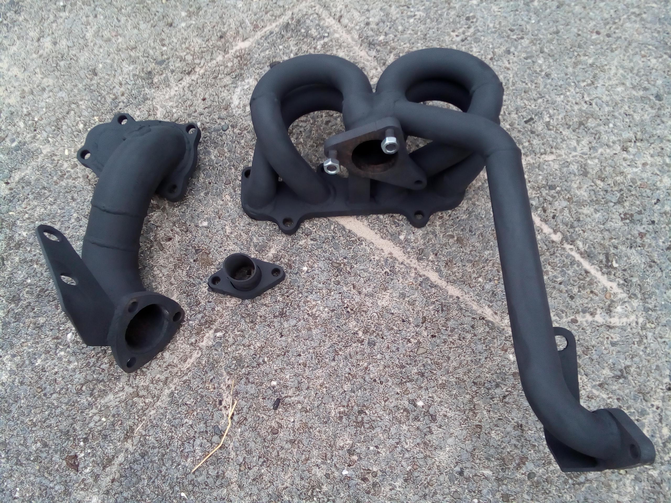
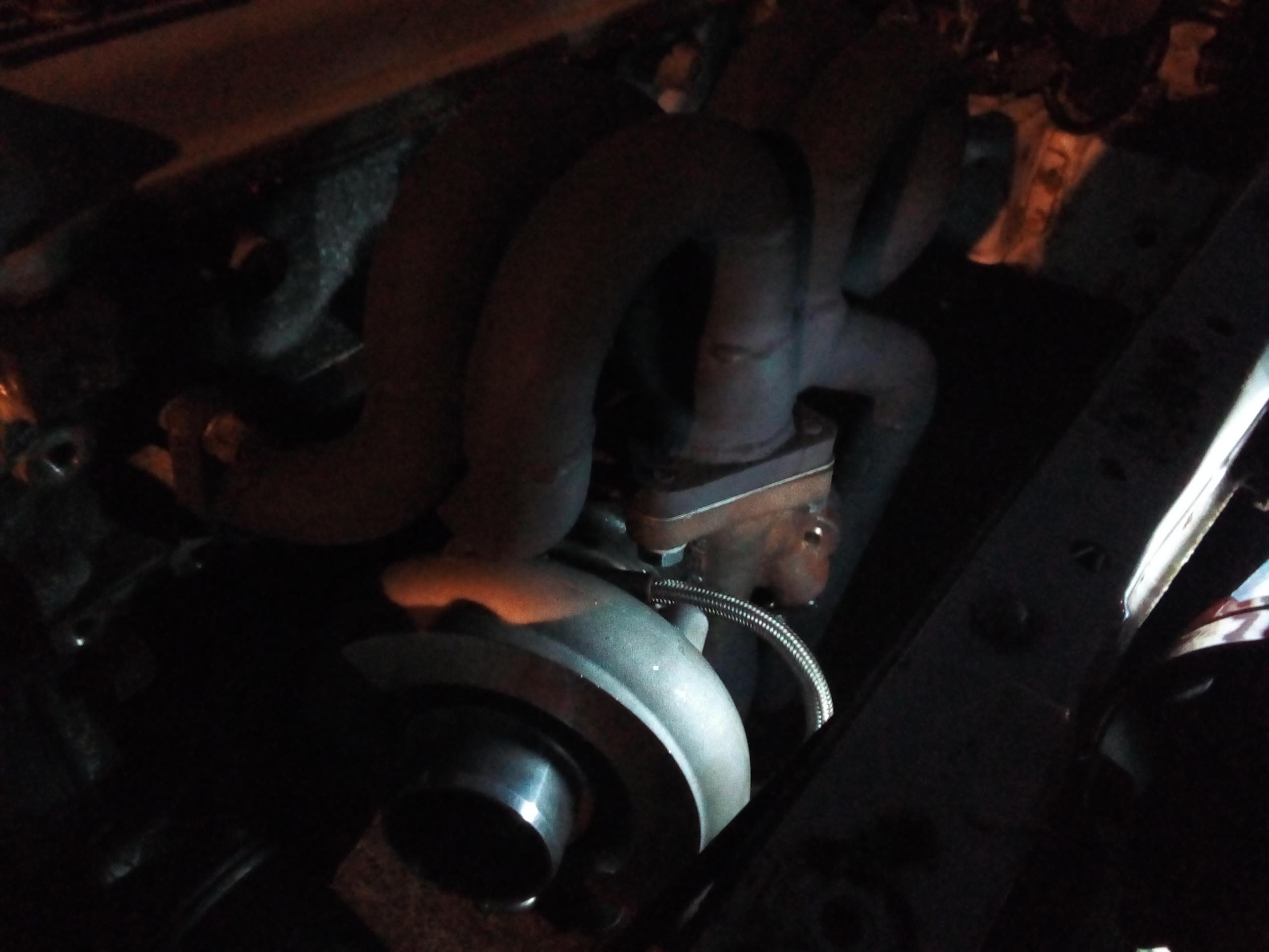
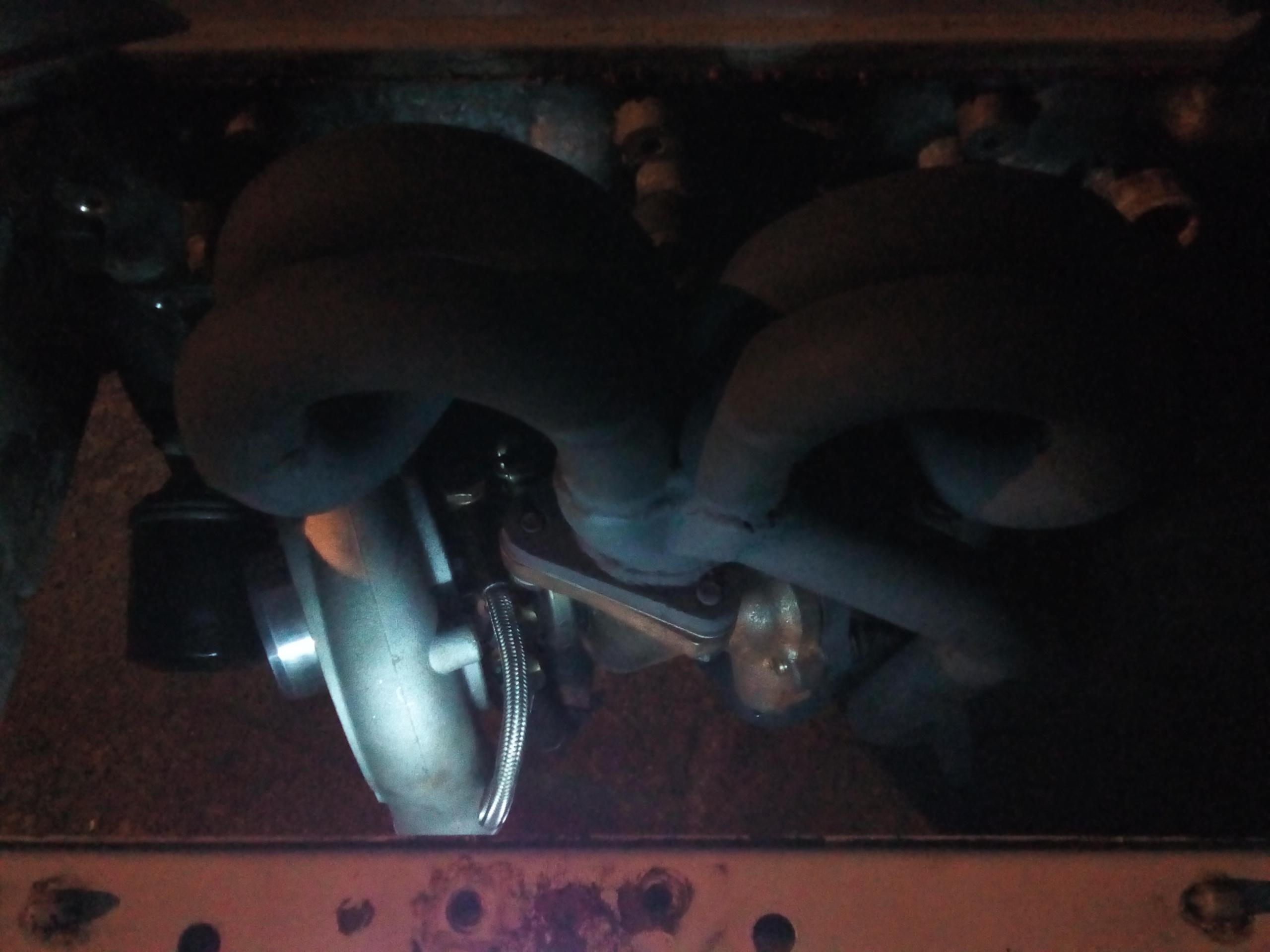
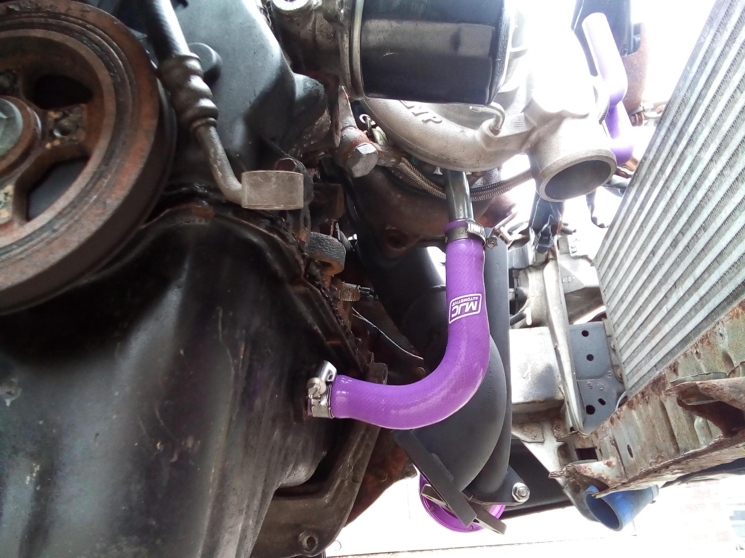
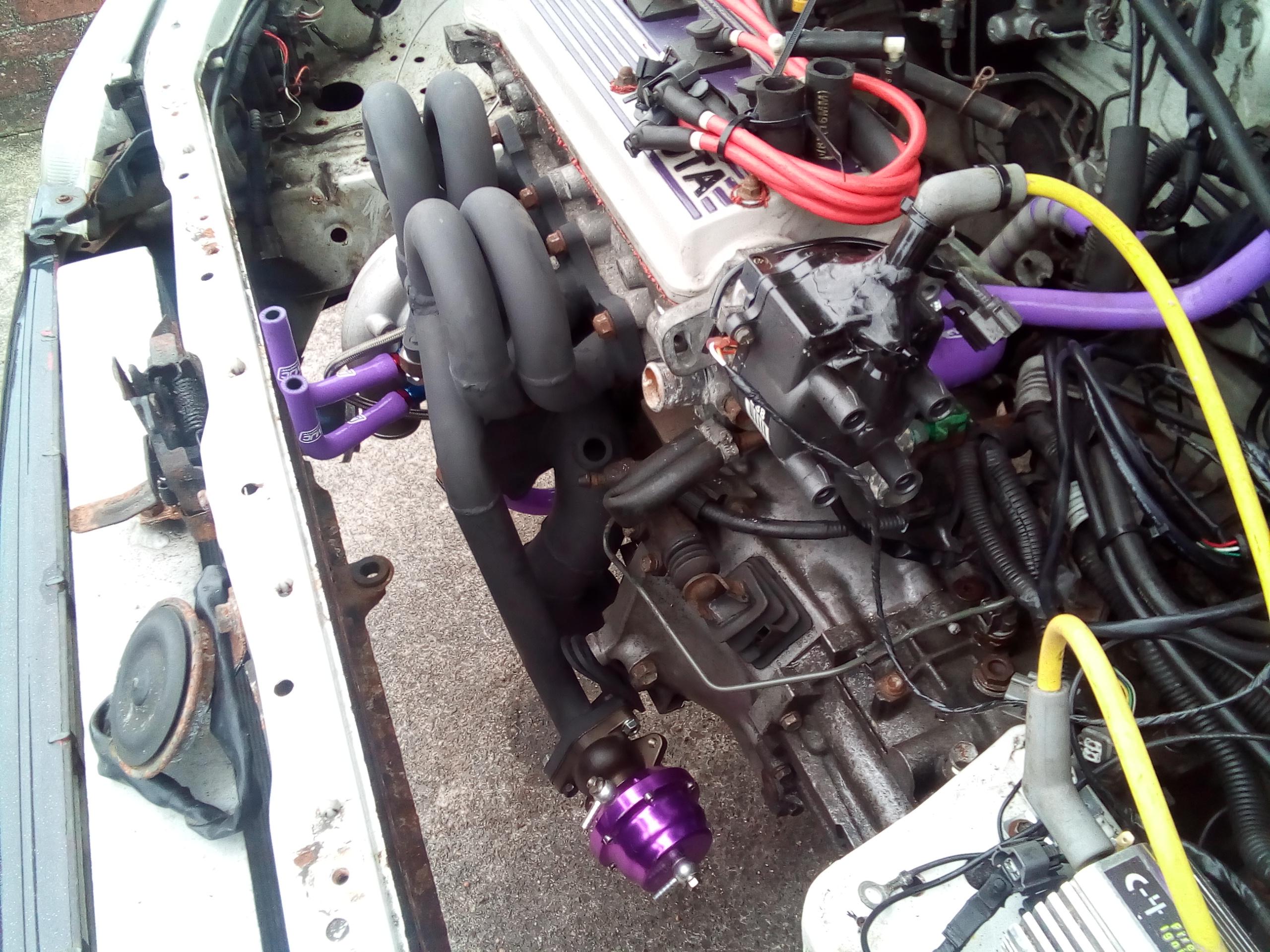
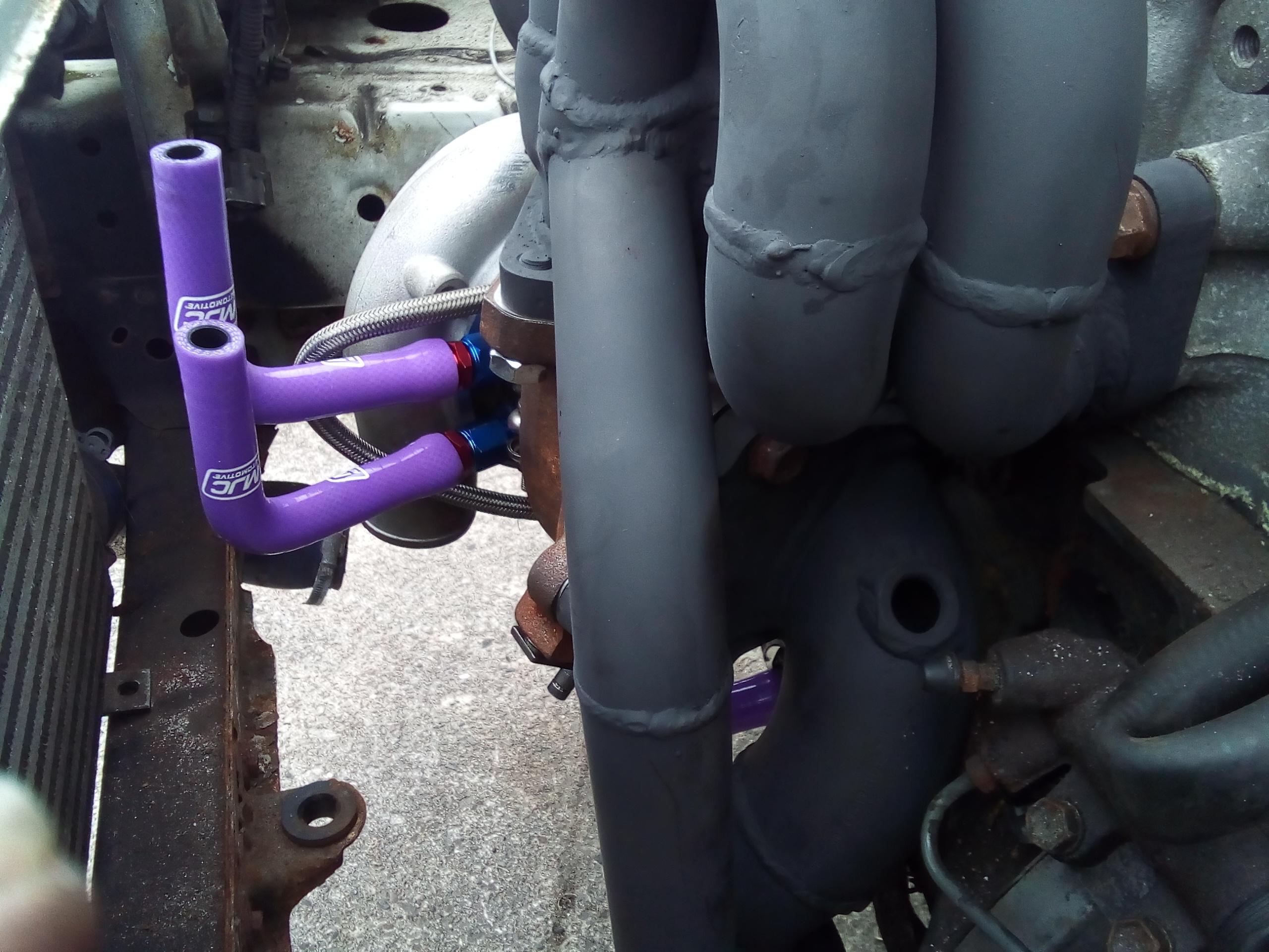
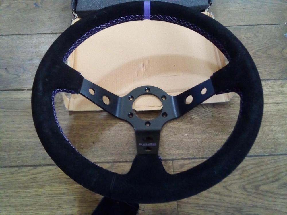
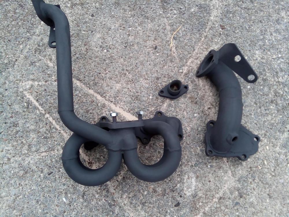
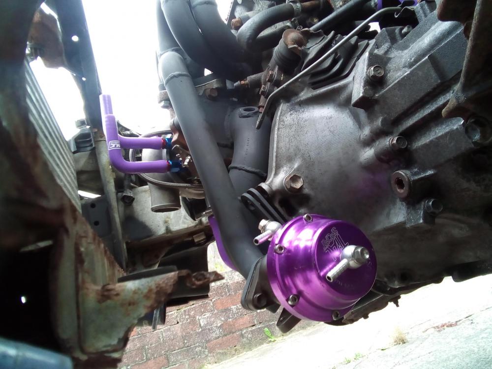
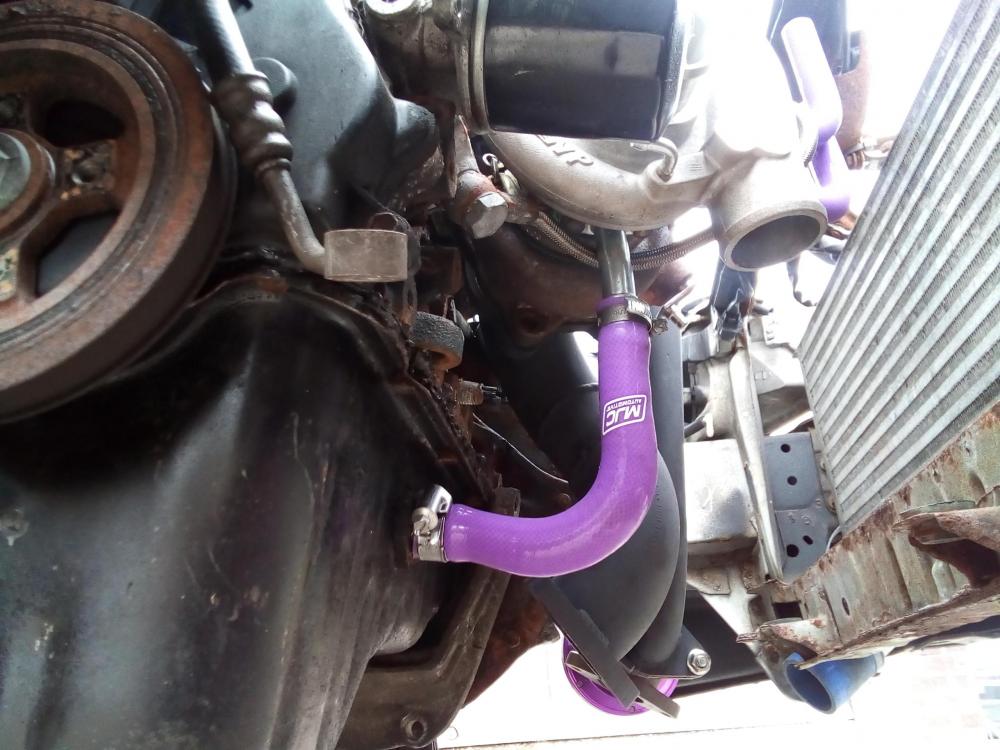
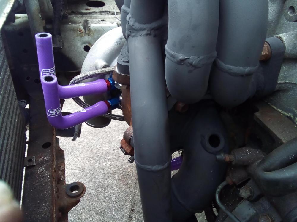
A good friend of mine has used the old zisco manifold and made a jig for this a new manifold/turbo kit. The turbo has evolved again this time using a td05 20g antisurge compressor housing modified to fit the 13t hybrid. I could not trust the surge I was getting with the 4e skinny rods. This should also pump more volume of air but at a smoother rate in the rpm band. The old 1 was good just heavy corrosion. He is fitting this new kit to car whilst I'm away. I'm currently making the pre turbo throttle body. Made up of 2x back to back 4e series throttle bodies 1x 4efe and 1x ,4efte striped out using a hks actuator to operate/open with turbo boost pressure. Time to start fabrication. All new nuts bolts and gaskets used. Refreshed. 1 word : PURPLE If this is to lazy I've have a rare tdo4hl exhaust housing and I'll use an 11 blade turbine. That's is alot lighter than the 9 blade option I'm running now. Bigger tdo4hl exhaust port. It's all coming together, and I must admit the help I've received from a young uni student I work with, ho has helped build up this ep91 and thought me a few tricks when it comes to mapping.As well as his attention to detail. Many many thanks. Using the close ratio gearboxes gives outstanding acceleration, this allow daniel to run big ignition retard low down in the rpm band. What this does is produce high flowing very hot exhaust gasses kicking off turbo spool. He just needs to stop loosing my tools !!!! Haha.


-
Now we are talking. All looking good.
-
Nice build.
-
No worries. I recon most of these now will have seized idle control gates. These cars/system is so so basic it's fun to just work out how it runs, very simply done. Enjoy.
-
I'll order a set now thanks dutchie I've been told on the corolla owners forum that some early 1998+ avensice brakes fit the corrolla calipers also both twin and single pots I'm getting full info soon, there's something about getting custom brake lines made thw.
-
Minor heat cracks Looking good. Nice stoping power there what size are them discs.
-
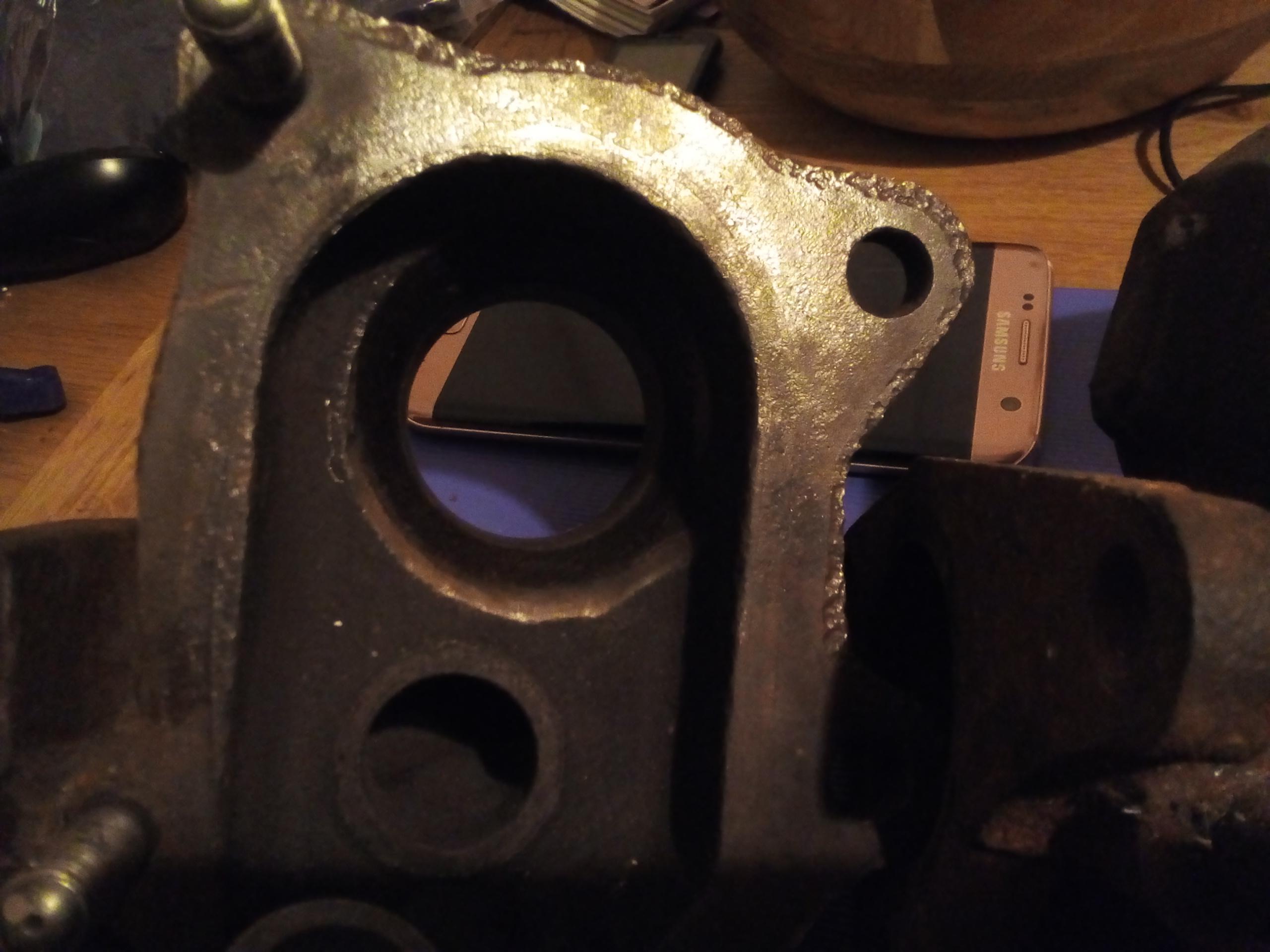
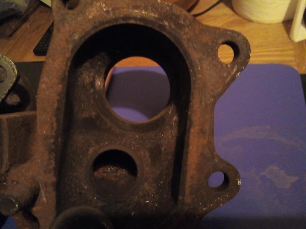
Thanks The caliper piston travel I'm getting needs the thicker discs I recon. I'm worried about the piston travel at max pad wear. The discs I ordered do not fit they were 5 stud Corsa D discs, But the MR2 front calipers fit to the corrola pad carriers with a slight grind/mod (this can be seen in 2nd pic on this topic). I've ordered some spigot rings also from custom spigot rings on the internet. I'll put up the full mod when I get the discs and spigot rings. Thanks guys the MR2 calipers are common and can be still bought new/reconed or 2nd hand. So can the corrola pad carriers. I'm also looking into the master cylinder travel for the larger volume calipers this will affect the starlet brake front to rear conpensater. Some Mitsubishi models have a larger master cylinder that will fit the starlet. Reducing the travel.
-
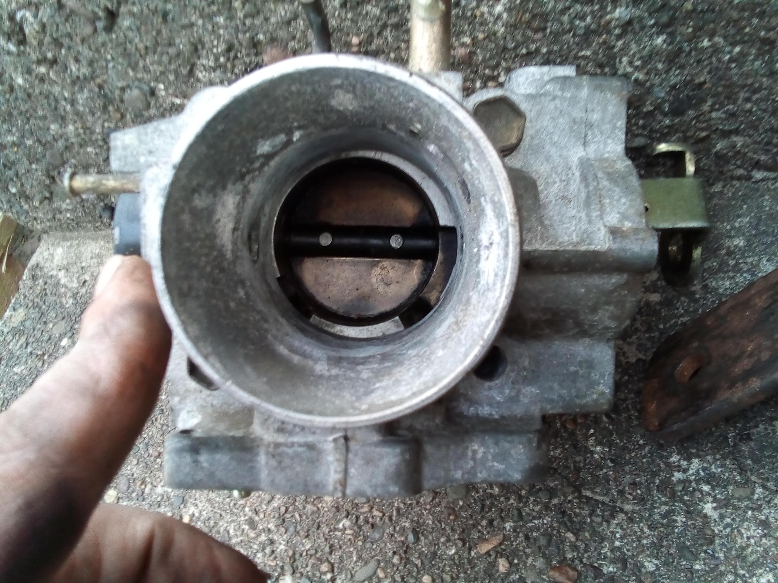
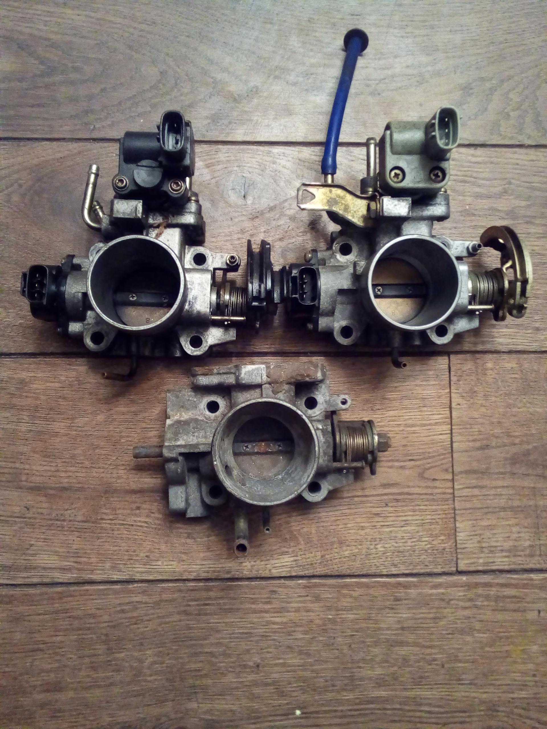
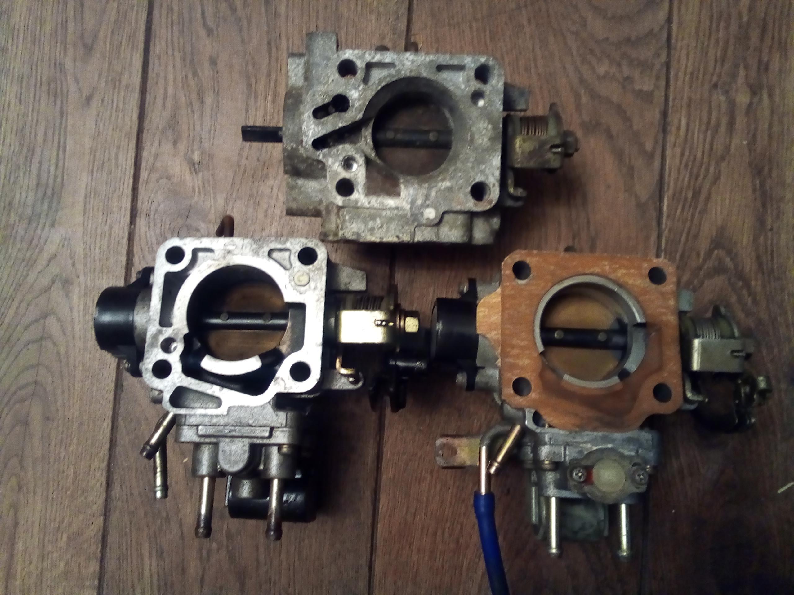
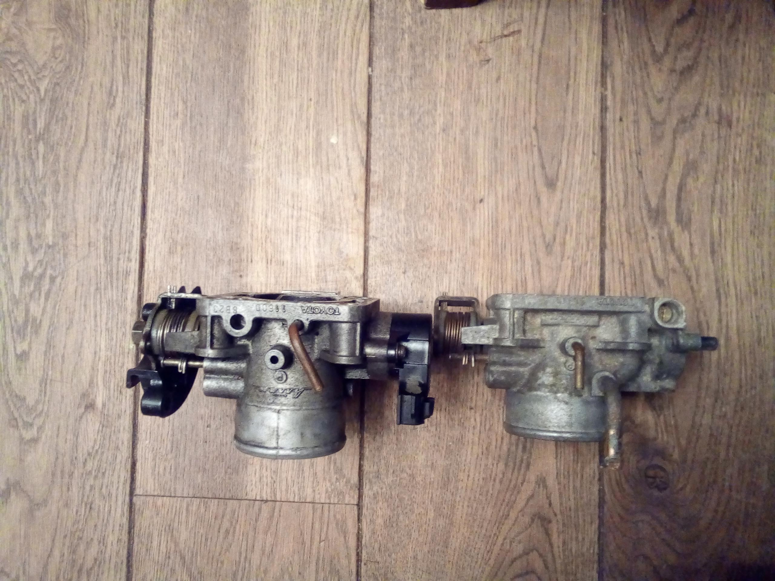
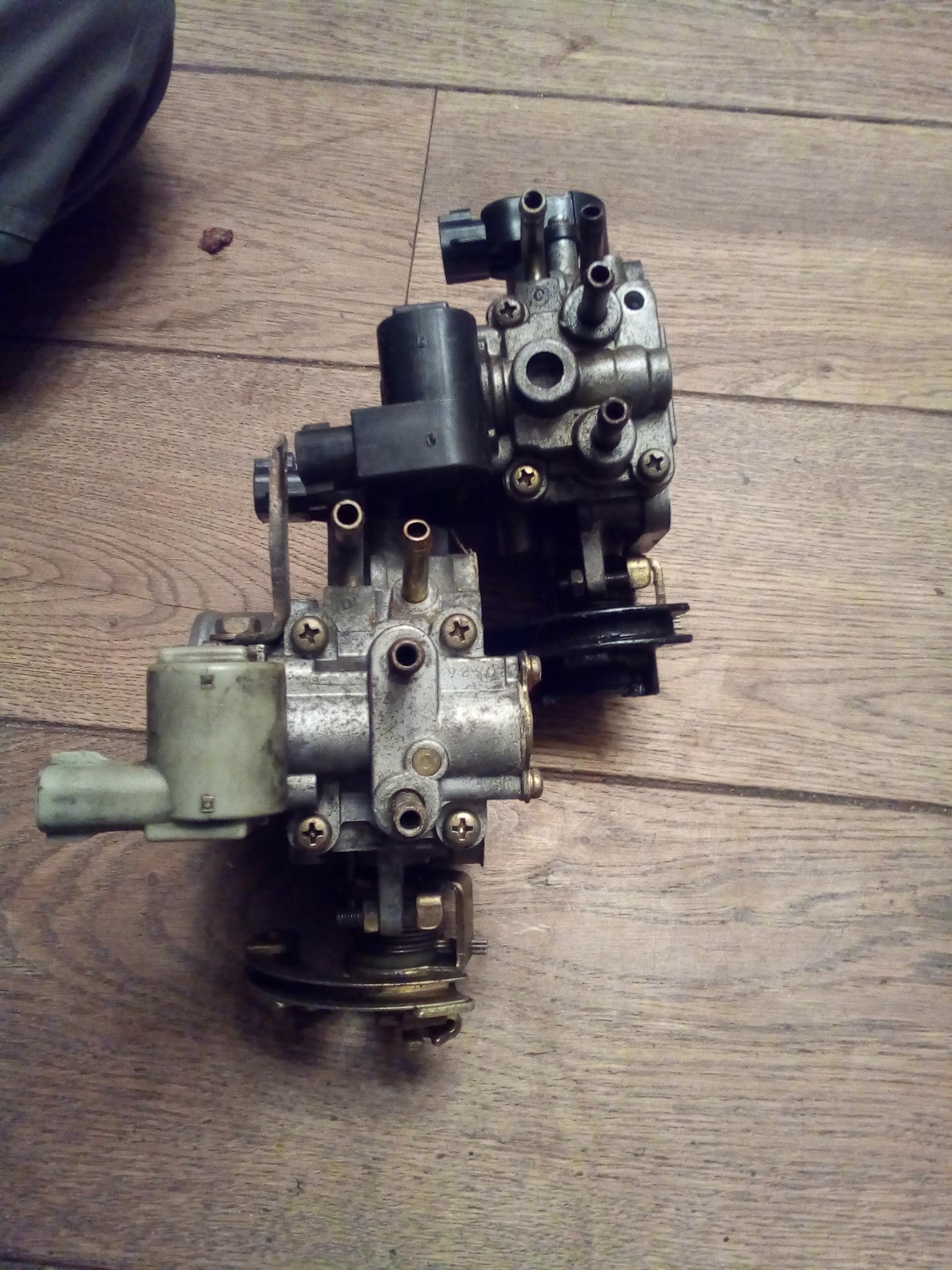
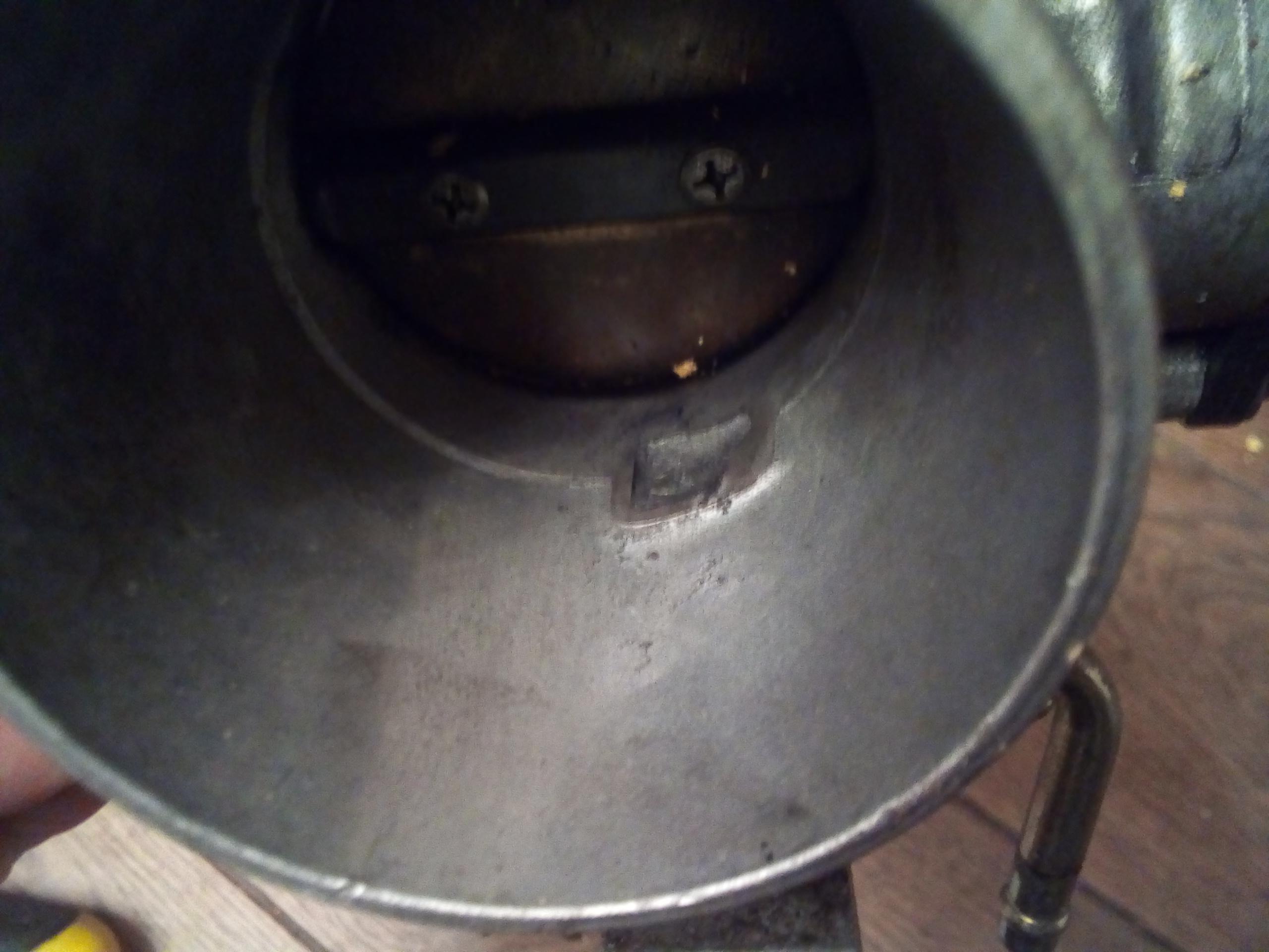
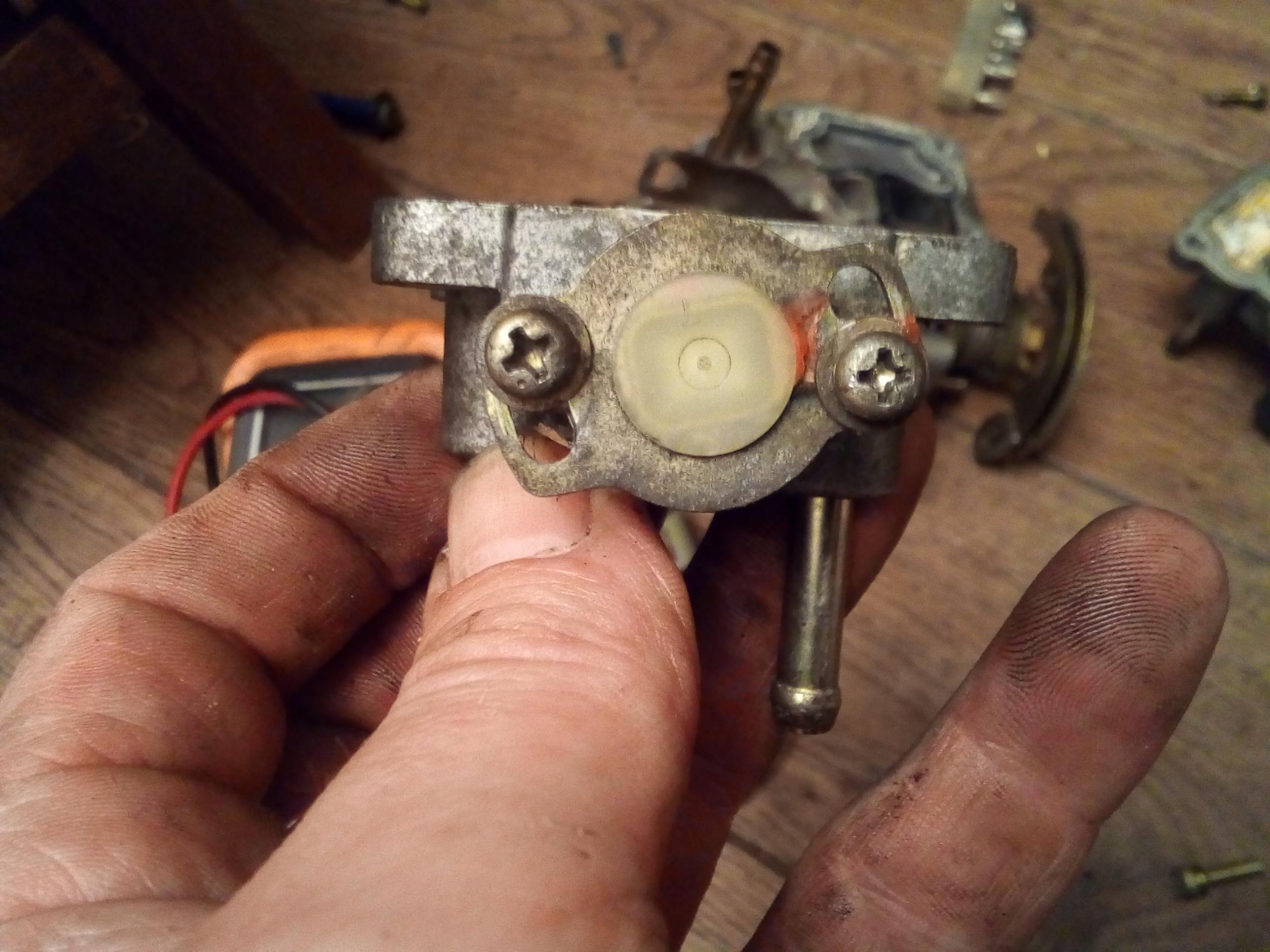
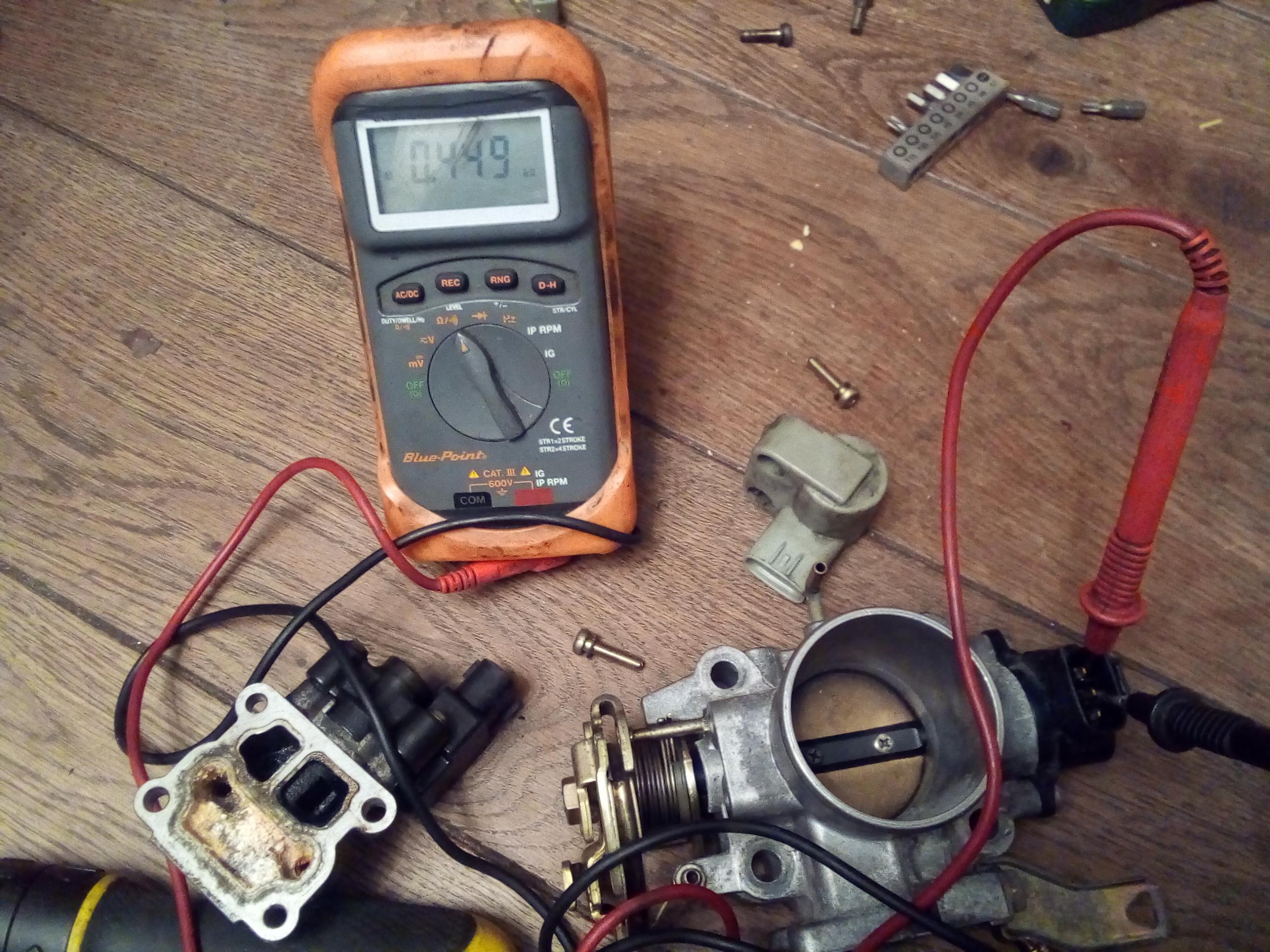
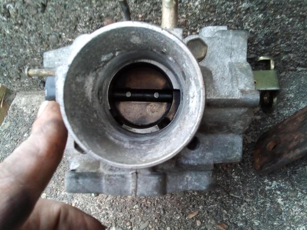
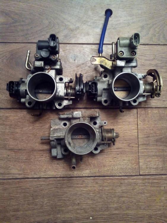
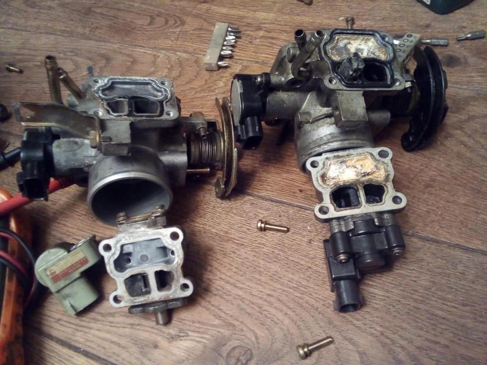
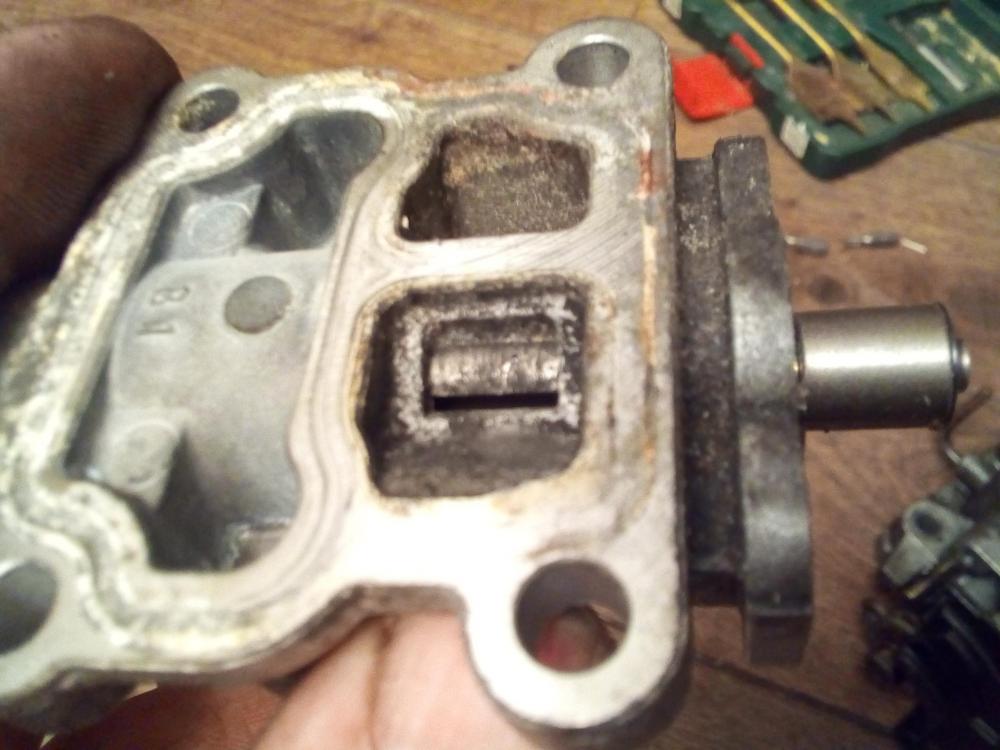
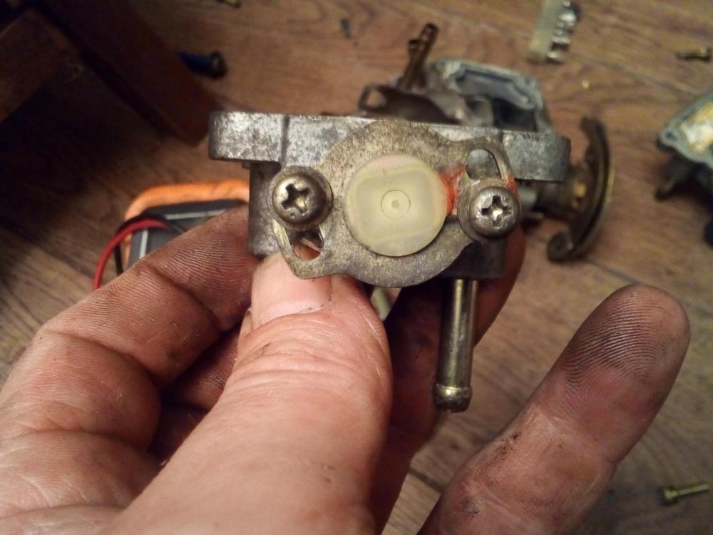
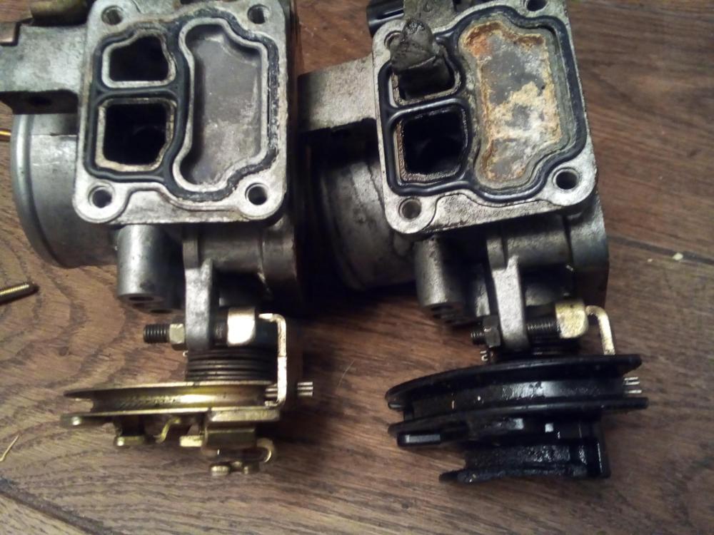
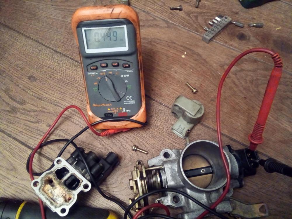
Yep Here's the throttles I have off the 4e engine The top 1 smaller butterfly is off the ep80 gi and COROLLA 1st gen used with the 4efte inlet manifold. More pictures to come I'll strip them down. The 1st gen has an idle adjustment screw on the top right side like on the turbo throttle. The 2 different idle control valves on the starlet. Both idle valves are seized solid in the alloy housing. The right 1 has been modified by someone you can see the steel putty coming out of the idle valve inlet. They must have adjusted the throttle arm stop screw to correct idle rpm. Steel putty blocking the inlet port. Idle control gate/arm seized and will not turn on both the throttle bodies. Might be a common issuse. This is for the idle arm return spring adjustment. Only found on 1 of the throttle bodies. Yep you can see the difference In the stop screw length. I would have sooner put a drill hole threw the butterfly to correct idle, this is because the ECM uses the throttle position to calculate engine load on an na engine. Standard tps idle position 449ohms Full throttle reading is 2800ohms.


-
Is the throttle body mucky in side. Would you be interested in setting up the tps and throttle butterfly. You will need a multimeter we can compare readings from the air temp sensor& coolant temp sensor engine cold. What year is yours I've got 2x Different idle control valves here Infront of me on 2x Toyota e series engines. I think 1 is off the 5e paseo but I was told the paseo has a 4 pin tps but these are 3pin With 2x different idle control valve setups.
-
Big help it looks like there are afew calipers that fit the corrola carriers with alittle moding. What kind of travel have you got on the brake peddle with these, how much free play.
-
Your welcome. Big fan of your build. Im striping an early 4efte head at weekend to port and polish it. If your interested in the valve springs.
-
It sounds like it could be the throttle stop setup. This is the Allen keyed adjusting screw on the throttle arm at rest position. Did you say it's a different throttle body. Also there is the intake air temp sensor and coolant temp sensor these adjust fueling if 1 is faulty if will fuel more but because of the large veriation of the sensors readout the ECU does not see a fault.
-

Claymore's sleeper 4efe+t-t+t build (R.I.P. the Nanza)
Sam44 replied to Claymore's topic in EP91 Progress Blogs
Yeh 2 of the best caps right there. Yeh I'm having the same issues. My email has been verified also. -
Great thread. There's some lads and lady's out there that really love starlets. What models were available??. I have the cd full electrical model with sun roof and adjustable steering column.
-
Claymore's sleeper 4efe+t-t+t build (R.I.P. the Nanza)
Sam44 replied to Claymore's topic in EP91 Progress Blogs
The best cap on the market for these seems to be the cosworth cap from demon tweeks. Most of the track starlets run this cap. It's the cap I'm running. I also run a restrictor cap/plate in the top hose to keep the block pressure up and in the block. When running higher cap pressures be mindful of the plastic radiators and factory old spring type hose clips!!!!. This area of the engine was the first thing I was warned about when becoming interested in the vehicle. As well as being told this is the main reason of engine failure low block pressure overheating internals, especially cast alloy pistons. When you look threw the site all the warning signs are there. I'm surprised it's not more commonly know about. All proformance engines I know of run a 30psi minimum block pressure that would mean a 2bar pressure cap using a standard Toyota e series system. First warning signs to look out for is ring filings in the engine oil, this looks like a metallic black paint, very fine filings (overheating piston crowns), poor ring seal (piston to bore contact) this is what removes/transfers the heat from the crown to the coolant, crank case air pressure might also increase (leaking engine oil seals), increased oil pump wear and seized little end will follow shortly after. -
Claymore's sleeper 4efe+t-t+t build (R.I.P. the Nanza)
Sam44 replied to Claymore's topic in EP91 Progress Blogs
Urmm nothing mad about it. It's quite simple it's the same system, you just use the radiator to help maintain block pressure. This is how most other engine manufactures work. I take it you aren't aware of the pressure cap problems at high rpm and temp. (Track action). A very valid point of filling the system. I always use pressure\vacum to fill the system and test for leaks, but as you have pointed out if you fill by hand there is a potential for an air lock if filled in a hurry and not bled threw. The coolant flows from The water pump to the engine block, threw the block to the cylinder head using the head gasket coolant ports located exhaust side (hot valve side) located only on cylinder 1&2 (furthest side away from thermostat side\block exit) block exit located on the gearbox side\cyl 4 side of the cylinder head. it then supply's the top radiator hose (large bore diameter), heater matrix inlet also provides the throttle body thermostat idle control valve on this line, turbo coolant inlet, and if the thermostat is closed/not at temp a very small diameter bore bypass port back to the pump (all incorporated in the thermostat housing) With the thermostat closed there will be no circulation threw the radiator but the top hose & pressure cap see engine pump pressure at all times. All proformance engines run a constant 30psi block pressure to stop air bubbles forming, but factory cap pressure is .9bar this is why they fail and spray coolant everywhere on track. Block pressure overpowers the cap to the point the main seal fails. I hope this helps understand the unusual Toyota e series design. Now if we switch the radiator hoses around the bottom hose now becomes high pressure side (engine pump/block pressure) and the top hose/rad cap low pressure side. Until system is upto temp. Eliminating pressure cap issues and helping stabilizing block pressure. -
Thank you for any information, any wear information off an engine of this age is most valuable, most do not last or get stripped for parts. I'm strictly interested in the vehicle and technical side. I'm not here to cause trouble any information gained I'll keep private. I'm just going to have a read back threw your build at power levels, and service information. As said you work fast she nearly out.